1
WIENER Mini Crate 395
User Manual
PRELIMINARY
General Remarks
The only purpose of this manual is a description of the product. It must not be interpreted as a declaration
of conformity for this product including the product and software.
W-Ie-Ne-R revises this product and manual without notice. Differences between the description in
manual and the product are possible.
W-Ie-Ne-R excludes completely any liability for loss of profits, loss of business, loss of use or data,
interrupt of business, or for indirect, special incidental, or consequential damages of any kind, even if WIe-Ne-R has been advises of the possibility of such damages arising from any defect or error in this
manual or product.
Any use of the product which may influence health of human beings requires the express written
permission of W-Ie-Ne-R.
Products mentioned in this manual are mentioned for identification purposes only. Product names
appearing in this manual may or may not be registered trademarks or copyrights of their respective
companies.
No part of this product, including the product and the software may be reproduced, transmitted,
transcribed, stored in a retrieval system, or translated into any language in any form by any means without
the express written permission of W-Ie-Ne-R.
Mains Voltage and Connection
The Power supplies are equipped with a “World”- mains input, which works properly form 94VAC up to
264VAC and within a frequency range of 47 to 63Hz. Before connecting to the mains please doublecheck correspondence.
Safety
After connecting the chassis to the mains and switching the AC MAINS on, the auxiliary power supply
module is powered permanently.
Do not open or work inside the power box area without first disconnecting the unit from AC mains.
Cooling
VME Mini Crates are equipped with temperature probes to protect the unit against severe damages. It
cannot be guaranteed that inserted modules are protected sufficient in the same way if
1. The fan speed is reduced to lower or minimum speed
2. The air ingress or/and outlet holes are blocked
12/6/2013
i
WIENER_395mini.v1.0
Table of contents:
1
General Information ........................................................................................................................ 3
1.1
395 Mini Crate Series Features ................................................................................................ 3
1.2
Front and Rear Side View........................................................................................................ 4
1.3
Cooling ................................................................................................................................... 4
1.4
Power Supply .......................................................................................................................... 5
1.5
Display and CML00 Shelf Manager......................................................................................... 6
1.5.1
CML DC ON/OFF Switch and Status LED ...................................................................... 6
1.5.2
Ethernet Connector .......................................................................................................... 7
1.5.3
USB Connector................................................................................................................ 7
1.5.4
CML Temperature Sensor Inputs / Fan Control ................................................................ 7
1.6
2
3
Ordering Information............................................................................................................... 9
WIENER 395 Mini Chassis Operation............................................................................................10
2.1
Main operation modes and associated submenus .....................................................................11
2.2
Front Panel LED’s..................................................................................................................12
Ethernet Remote Monitoring and Control .......................................................................................13
3.1
SNMP communication protocol ..............................................................................................13
3.2
SNMP Control Examples........................................................................................................18
3.3
Setting of IP Addresses via SNMP..........................................................................................19
3.4
Change of Community Names / Setting of Passwords .............................................................19
3.5
WIENER SYScontrol Software .............................................................................................20
3.5.1
Installation SYScontrol ...................................................................................................20
3.5.2
Setting Preferences / IP Address and Crate Scan..............................................................20
3.5.3
The SYScontrol Main Window .......................................................................................21
3.5.4
SYScontrol - Outputs ......................................................................................................21
3.5.5
SYScontrol – Fans ..........................................................................................................22
3.5.6
SYScontrol – Temperature Sensors .................................................................................23
3.5.7
SYScontrol Networks tab................................................................................................23
3.6
MIB Browser..........................................................................................................................24
4
Technical Details VME / VME64x / cPCI Mini crate 395...............................................................25
5
CML Firmware Update Instructions ...............................................................................................26
12/6/2013
ii
WIENER_395mini.v1.0
User’s Manual
395 Mini Crate Series
W-Ie–Ne-R
Plein & Baus GmbH
1
General Information
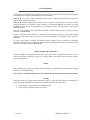
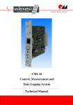
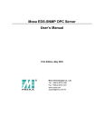
The WIENER 395 mini crate series represents a compact but modular designed 9 slot
VME/VME64x/cPCI chassis with hot-swappable, redundant power supplies. A front-side-plug high
performance DC fan is used for cooling with front to rear air flow.
The front side 6U x 1600 mm card cage is recessed . The 395 crate series is also outfitted with a rear
side 6U x 80mm transition card cage. All chassis parts are compliant to the IEEE 1101.10 standard
with enhanced EMC / ESD.
One or two redundant operating plug-in 250W cPCI power supplies provide sufficient power for all
applications. The CML shelf manager allows full remote monitoring and control of power supply, fan
and chassis.
The WIENER 395 mini crate can be used on the desk either as a desktop or up-right unit or be
installed in a 19” rack.
Fig. 1.1: 3-dimensional view of VME395x chassis
1.1
395 Mini Crate Series Features
MINI-Bin mechanics for 6Ux160mm modules, suitable either for 19" rack, as a tower- or a
desktop box
IEEE 1101.10 compliant mechanics with enhanced EMC / ESD
9 slot monolithic VME, VME64x (optional P0 connectors) or cPCI backplane
Free rear access for 6U transition modules, standard transition cage for 6U 80mm modules,
provisions for 160 and 120mm foreseen. Special depth on request
Alphanumeric high-visibility LED display for voltages, currents, fan speed, temperatures and
settings / programming, 4 status LED’s
WIENER CML Shelf Manager for local and remote monitoring and control, monitors and
controls power supply, fan, remote on/off, SYSRES, thermal monitoring, user I/O
programming, with Ethernet and USB interfaces, rear side plugged in
Front side mounted, removable High-RPM DC blower, adjustable speed (1200 … 3200
RPM), temperature controlled
Programmable under / over voltage and over current trip points, active DC output discharge
12/6/2013
3
User’s Manual
395 Mini Crate Series
W-Ie–Ne-R
Plein & Baus GmbH
Outfitted with one or two 250W cPCI power supplies, plugged in from rear, hot swappable,
redundant operation, CE-conformity, 300W power supplies on request
100V – 240V world-wide auto-range AC input, with power factor correction, CE-conformity
Dimensions: 19” (482mm) x 5U (215mm) x 417mm [whd], weight: ca. 20 kg
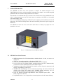
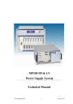
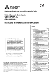
1.2
Front and Rear Side View
Alphanumeric
display
Status LED’s
on/off, mode,
fan speed
switch
9 slot VME64x
card cage,
6U x 160mm
Air inlet and
DC fan
Fig. 1.2: Front side view of VME395x-2 chassis (without 19” rack mounting brackets)
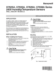
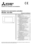
PS cooling air outlet
Main air outlet
cPCI power supplies
CML (Ethernet,
USB) ports
Rear side
transition
card cage,
6U x 80mm
AC input, IEC 13
with AC-Mains
switch and fuse
Fig. 1.3: Rear side view of VME 395x_2 chassis (without 19” rack mounting brackets)
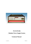
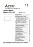
1.3
Cooling
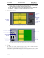
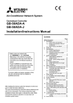
The 395 mini crate provides a front-to-rear cooling air flow. In order to maximize the air flow
additional air outlets are provided on the side and top of the chassis.
A part of the air is internally divided and guided to the rear for cooling of the power supply as well as
of the transition card guide area. The following plot shows the cooling air schema of the 305 crate.
12/6/2013
4
User’s Manual
W-Ie–Ne-R
395 Mini Crate Series
Plein & Baus GmbH
Fig. 1.4: Principle cooling air flow
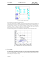
The fan assembly on the front side is field removable.
Using a high performance DC fan (HRPM – high speed) in push mode an extremely high airflow and
static back pressure is achieved. The maximum fan speed is 7200rpm and can be reduced stepwise via
front panel switch operation or remote control to 2400rpm. The fan operation can be temperature
controlled in case the 395 chassis is outfitted with optional temperature probes. The fan speed is
monitored and a fan fail circuit will shut down power in case of failures.
For enhanced cooling the fan will run a defined time (default 60s) after switching off the chassis.
Fig. 1.5: HRPM fan airflow / static pressure characteristics
1.4
Power Supply
The 395 mini crate is outfitted with either one or two cPCI-type 250W power supplies. Optionally
also 300W power supply versions are available. The power supplies are hot-swappable and can
operate in a redundant mode. No minimum load is required. The following table provides the output
current rating for the 250W power supply.
12/6/2013
5
User’s Manual
W-Ie–Ne-R
395 Mini Crate Series
Plein & Baus GmbH
Voltage
5V
3.3V
Minimum
0A
0A
Typical
25A
18A
Max
33A
33A
Peak.
33A
33A
+12V
-12V
0A
0A
5A
0.5A
5.5A
1A
6A
1.5A
Notes: 1.Peak load less than 60sec. with duty cycle <10%.
2.Max. load is the continuous operating load of each rail. But the max. load of each rail can't
be drawn from all outputs at the same time.
Using a special internal power backplane additional filtering and current measurement is provided.
This internal board is also outfitted with crow bars for an active discharge on all DC lines in error
conditions and when powering down.
With the help of the CML Over Voltage (OV), Under Voltage (UV) and Over Current (OC) trip
points can be defined.
1.5
Display and CML00 Shelf Manager
For local and remote monitoring and control the 395 mini crate is outfitted with a CML00 shelf
manager and a high visibility alphanumeric display. In addition to the display of voltages / currents,
temperatures, fan speed and networking it is possible to program most of the chassis and power
supply settings using the front panel switches (see paragraph 2).
The CML00 allows full remote monitoring and control of power supply, fan and chassis parameters
via Ethernet (SNMP v2 and WWW) and offers the following features:
Remote or local switch ON/OFF
Multicolored status LED
12 bit DC Voltage measurement: 4 channels for 3.3V, 5V, 12V and -12V
Temperature measurement: 1-wire-bus for digital temperature sensors
Fan Control: DC fan monitored, fan speed settable, temperature controllable
Fully controlled, programmable trip thresholds (min./max. Voltage & temperature)
Detection of VME RESET and SYSFAIL, generation of VME RESET and ACFAIL,
Detection of Derating or Failure signals from cPCI Power Supplies
Capable to switch cPCI Power Supplies (ON/OFF)
Ethernet connection IEEE 802.3 10BASE-T and IEEE 802.3u 100BASE-TX
WWW-Server integrated, full control via SNMP protocol v.2
PC-Control (connected to galvanic isolated USB) with free available software
IP address settable to a fix value or configurable via DHCP (default)
Firmware update possible via USB or Ethernet.
Automatic data logging on Windows/Linux computer possible
Digital Signal Processor (DSP) for real-time processing of all measured data
Powered by 5V bus voltage and independent power supply
Configuration permanently saved in EEPROM
1.5.1 CML DC ON/OFF Switch and Status LED
The CML is outfitted with a DC Power Switch which is used to switch the system power supply on
(push the switch to the “ON” position) or off (push the switch to the “OFF” position.
The multi-colored Status LED shows the global status of the system:
YELLOW Standby state (the system power supply is off)
GREEN System power is on, all measurement values are in limit
RED System switched off because of any failure
12/6/2013
6
User’s Manual
395 Mini Crate Series
W-Ie–Ne-R
Plein & Baus GmbH
1.5.2 Ethernet Connector
RJ45 Socket
Pin
Signal
1
TX+
2
TX-
3
RX+
4
GND 1
5
GND 1
6
RX-
7
GND 2
8
GND 2
Comment
This is the standard NIC configuration. You need a 1:1-cable to connect a to a HUB, or a cross-over
cable to connect to another NIC (e.g. a computer). There is no automatic signal crossing like with
some routers.
1.5.3 USB Connector
USB Socket
Pin
Signal
1
VCC
2
D-
3
D+
4
GND
Comment
This is the standard USB connector type B. The USB connection is galvanic isolated from the system
to prevent ground loops.
1.5.4 CML Temperature Sensor Inputs / Fan Control
The CML00 can be connected to 8 or more temperature sensors via a 1-wire bus. In the event of an
error, the status LED on the front panel will turned red.
The temperatures can be read with the SNMP network command (crate.sensor.sensorTemperature
OID).
Each temperature is compared with three threshold values (crate.sensor.sensorWarningThreshold,
crate.sensor.sensorAlarmThreshold and crate.sensor.sensorFailureThreshold OIDs).
Two different modes can be set. Please read more about the hysteresis control mode and the linear
control mode in the following paragraph.
To operate the device in the hysteresis control mode, it is necessary to swap the alarm with the
warning temperature value. The alarm temperature has to be less than the warning temperature. The
fan speed executes a hysteresis between the two temperature points of any connected sensor between
maximum speed and the nominal and minimal speed respectively .
If the sensorFailureThreshold of any connected sensor is reached, the main power supply of the
system is switched off.
The controlling result of fan speed is pictured in figure 1.6.
12/6/2013
7
User’s Manual
395 Mini Crate Series
W-Ie–Ne-R
Plein & Baus GmbH
Figure 1.6: Hysteresis control mode
The second mode is the linear control mode. If the temperature of any connected sensor is under the
warning threshold the fans will operate in their nominal and minimum speed respectively.
If the sensorWarningThreshold is reached, all fans will rotate in a calculated linear temperaturesensitive speed. Overstepping the sensorAlarmThreshold they will switch to their maximum speed.
After exceeding the sensorFailureThrehold of any connected sensor, the main power supply of the
system is switched off.
The controlling result of fan speed is pictured in figure 1.7.
Figure 1.7: Linear control mode
When using the linear control mode it is important to know that there exists a sub mode called low
noise mode. When the nominal speed set by user is under the allowed minimal speed, the device will
switch off all fans. If is it not necessary to cool down the device the fans stand still. After reaching of
sensorwarningThreshold the behavior of fan control is equal to the linear control mode.
The controlling result of fan speed is pictured in figure 1.8.
12/6/2013
8
User’s Manual
W-Ie–Ne-R
395 Mini Crate Series
Plein & Baus GmbH
Figure 1.8: Low noise control mode
1.6
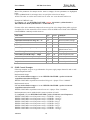
Ordering Information
VME / VME64 Crate Version
VME 395_1
VME 395_2
Backplane
VME/VME64
VME/VME64
VME64x Crate Version
VME 395x_1
VME 395x_2
VME 395x_1_P0
VME 395x_2_P0
Backplane
J1/J2 VME64x
J1/J2 VME64x
J1/J0/J2 VME64x
J1/J0/J2 VME64x
+5V
33A
66A
33A
66A
cPCI Crate Version
PCI 395_1
PCI 395_2
Backplane
6U cPCI
6U cPCI
+5V
33A
66A
12/6/2013
9
+5V
33A
66A
+12V
6A
12A
-12V
1A
2A
+3.3V
33A
66A
33A
66A
+12V
6A
12A
6A
12A
-12V
1A
2A
1A
2A
+3.3V
33A
66A
+12V
6A
12A
-12V
1A
2A
User’s Manual
W-Ie–Ne-R
395 Mini Crate Series
Plein & Baus GmbH
2
WIENER 395 Mini Chassis Operation
Switch on the AC Mains switch located at the power connector on the rear side.
To power the chassis on either the DC ON/OFF switch on the CML00 (rear side) or the “Power” on
the front display can be used on by pushing the switch up.
The main operation modes can be selected by pushing the “Mode Select” switch up or down.
Many main operation modes do have one or more submenus, which can be accessed by the following
special procedure.
You will use the following switches of the 395 mini chassis front panel:
Symbol
Description
Remarks
Push “Power” switch up (ON)
Main operation mode:
Switch the crate on.
Submenu:
OK button. Used to enter the selected
submenu, request to change a value,
accept the changes.
P
Push “Power” switch down
(OFF)
Main operation mode:
Switch the crate off.
Submenu:
CANCEL button. Used to leave a submenu,
discard the changes.
Push “Mode Select” switch up
Main operation mode:
Select the next operation mode.
Submenu:
Change the selected item to the next
possible state.
Push “Mode Select” switch
down
Main operation mode:
Select the previous operation mode.
Submenu:
Change the selected item to the previous
possible state.
The following example describes the detailed steps to change the IP gateway address of the fan tray.
Description
Switch
Display
( when 2 lines: display alternating
marked blue: flashing
switch the crate on
+5V 5.01V 1.2A
select the requested main M
or M
(until right TCPIP: no link
operation mode
mode is displayed)
enter submenu
12/6/2013
M (push and hold), P
Config: Wait
hold both switches up
Config: Wait...
after 4 seconds you can
Config: Ready !
10
User’s Manual
W-Ie–Ne-R
395 Mini Crate Series
Plein & Baus GmbH
release the switches
TCPIP Address
192.168.91.80
Select submenu “TCPIP M
or M
(until right TCPIP Gateway
Gateway”
menu is displayed)
192.168.91.94
Enter this menu
Change the value
2.1
192.168.91.94
or M
196.168.91.94
Accept change, to next P
item
196.168.91.94
Accept change, to next P
item
196.168.91.94
Accept change, to next
item
196.168.91.94
Ready, back to submenu
selection
TCPIP Gateway
196.168.91.94
Ready, leave submenu
TCPIP: no link
Main operation modes and associated submenus
Operation
Mode
Submenu
Display
Display voltage and current of the selected output channel
Change of the over current switch-off threshold
+5V0 IOff 60.A
Change of the under voltage switch-off threshold
+5V0 Umin 4.50V
Change of the over voltage switch-off threshold
+5V0 Umax 5.50V
Display the total power at the load
Power 10W
Auto Power Setting (Yes / No)
Auto PowerOn: Yes
SwitchOff (Normal / Delay)
SwitchOff: Normal
ScreenSaver (On / Off)
ScreenSaver: Off
Display the TCP/IP connection state
Possible values & symbols are:
no link (no cable connected)
10M (connected to 10M network)
100M (connected to 100M network)
HD (half duplex)
FD (full duplex)
, , (Frame received, transmitted, both)
12/6/2013
+5V0 5.01V 2.41A
Ethernet 100M FD
Change the TCP/IP address (0.0.0.0.0 = DHCP)
TCPIP Address
0.0.0.0
Show Assigned IP address
Assigned IP Add.
192.168.91.80
Change the TCP/IP subnet mask
TCPIP SubnetMask
255.255.255.224
11
User’s Manual
W-Ie–Ne-R
395 Mini Crate Series
Plein & Baus GmbH
Change the TCP/IP gateway address
TCPIP Gateway
192.168.91.94
Change Boot Option
ALL/BOOTP/DHCP
Allow writes (e.g. switch on/off) via the web server
HTTP:read/write
Change TCP/IP negotiation settings
TCPIPnegotiation
AutoNegotiation
Display of the Ethernet hardware address (MAC).
This address is written at the type plate, too.
TCPIP MAC Addres
0050-C22D-C231
Change the TCP/IP port of the web server
HTTP Port
Change the TCP/IP port of the TELNET server
TELNET Port 23
Change the TCP/IP port of the SNMP server
SNMP Port
Restore the default SNMP settings (community
strings)
SNMP Default No
Display the fan rotation speed
80
161
FANS: 2400 RPM
Change the time for which the fans will continue
running after switching the power supply off.
60s (default)
Display the number of supervised fans
1
Display the fan operating time (hours)
FanTime: xxx.x h
Display Fan Operation Mode
FAN MOD linear
Display the BIN sensor temperature (1 to 8)
Bin TempX: xxºC
Change the WARNIG threshold temperature (fans
will switch to full speed)
Change the ERROR threshold temperature (power
supply is switched off)
Change the FAIL threshold temperature (power
supply is switched off)
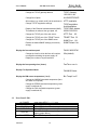
2.2
Front Panel LED’s
AC POWER
STATUS
FAN FAIL
OVERHEAT
SYS FAIL
FAN SPEED
12/6/2013
green large LED if POWER is on
green LED if all voltages are within the limit
yellow LED if a fan failure is recognized
yellow LED if an overheat in the power supply occurs
red LED if VME-bus system generates the SYSFAIL
signal (system failure)
Red LED if fan speed below 100%
12
User’s Manual
395 Mini Crate Series
W-Ie–Ne-R
Plein & Baus GmbH
3
Ethernet Remote Monitoring and Control
All WIENER crates with Ethernet ports allow simple monitoring and control via a web browser which
shows status as well as all supply voltages, fan speed and temperatures. It is possible to switch the
crate on or off, send a system Reset (VME: SYSRES) and change the fan speed within the web
browser window. All active controls as on/off and change fan speed will require a user name and
password. The user name is “private” and default password also “private” (can be changed via
SNMP).
The network configuration as IP address (0.0.0.0 default = DHCP), net mask and ports can be
changed via the front panel display and switches or via SNMP.
For full control of crate and power supply parameters or to implement the crate into a slow control
system WIENER is providing a SNMPv2c (Simple Network Management Protocol) compliant
protocol. We suggest NetSNMP as an open source SNMP program which will be used in the further
description. Please see http://net-snmp.sourceforge.net/ for more details.
3.1
SNMP communication protocol
Please download and install netSNMP (32-bit version!!! can be downloaded from file.wiener-d.com)
on the control computer. In order to perform SNMP calls from any WIENER product the WIENERCRATE-MIB.TXT file must be stored somewhere on the PC doing the calls, by default that location
should be /usr/share/snmp/mibs (Windows: C:\usr\share\snmp\mibs). The most commonly used
netsnmp calls are:
snmpwalk – returns groups of parameters / items
snmpget – returns a specific parameter (read)
snmpset – sets a specific parameter (write)
Please see the Net-snmp description and help files for detailed instructions and options. All
parameters defined for the WIENER crates and other power supplies are contained within the
WIENER-CRATE-MIB.txt file.
A fast an easy way to begin using SNMP is to use command line arguments. The command line
arguments specified in this document are based on netSNMP. The command line syntax is the same
for both windows and Linux (and MAC OSX).
For all WIENER-CRATE-MIB library calls a quick help text can be shown by using
12/6/2013
13
User’s Manual
W-Ie–Ne-R
395 Mini Crate Series
Plein & Baus GmbH
snmptranslate -On -Td WIENER-CRATE-MIB::xxxx
Example:
snmptranslate -On -Td WIENER-CRATE-MIB::outputName
.1.3.6.1.4.1.19947.1.3.2.1.2
outputName OBJECT-TYPE
-- FROM WIENER-CRATE-MIB
-- TEXTUAL CONVENTION DisplayString
SYNTAX OCTET STRING (1..4)
DISPLAY-HINT "255a"
MAX-ACCESS read-only
STATUS current
DESCRIPTION "A textual string containing a short name of the
output. If the crate is equipped with an alphanumeric
display, this string is shown to identify a output channel."
::= { iso(1) org(3) dod(6) internet(1) private(4) enterprises(1) wiener(19947) c
rate(1) output(3) outputTable(2) outputEntry(1) 2 }
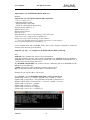
A first communication with a WIENER chassis can be done using the snmpwalk to confirm the
existence of the unit at the given IP address.
snmpwalk -Cp -Oqv -v 2c -M $path -m +WIENER-CRATE-MIB -c public $ip
with:
snmpwalk: This command will retrieve a block of information.
-v 2c: This parameters specifies which version of the SNMP to use. WIENER devices use SNMP 2C.
-M $path: This parameter should be replaced with the path to the WIENER-CRATE-MIB.txt file. It
is not needed in case the default path is used.
-m +WIENER-CRATE-MIB: This parameter tells the command to look at the WIENER-CRATEMIB to resolve the OID name.
-c public: This specifies which community of values can be accessed.
$ip: This should be replaced with the IP address of the MPOD crate.
Example for crate with IP address 192.168.0.81:
C:\ >snmpwalk -v 2c -m +WIENER-CRATE-MIB -c public 192.168.92.198
SNMPv2-MIB::sysDescr.0 = STRING: WIENER Crate ( CML00 2.1.1930.0)
SNMPv2-MIB::sysObjectID.0 = OID: WIENER-CRATE-MIB::sysMainSwitch.0
DISMAN-EVENT-MIB::sysUpTimeInstance = Timeticks: (676068) 1:52:40.68
SNMPv2-MIB::sysContact.0 = STRING:
SNMPv2-MIB::sysName.0 = STRING:
SNMPv2-MIB::sysLocation.0 = STRING:
SNMPv2-MIB::sysServices.0 = INTEGER: 79
12/6/2013
14
User’s Manual
395 Mini Crate Series
W-Ie–Ne-R
Plein & Baus GmbH
A list of all available parameters or sub-parameters as for instance channels can be obtained using the
command snmpwalk with the parameter “crate”. To get all parameters use:
snmpwalk -Cp -Oqv -v 2c -M $path -m +WIENER-CRATE-MIB -c public $ip crate
example:
C:\ >snmpwalk -v 2c -m +WIENER-CRATE-MIB -c public 192.168.2.198 crate
Returns for the VME395x-2 crate:
WIENER-CRATE-MIB::sysMainSwitch.0 = INTEGER: on(1)
WIENER-CRATE-MIB::sysStatus.0 = BITS: 80 mainOn(0)
WIENER-CRATE-MIB::sysVmeSysReset.0 = INTEGER: 0
WIENER-CRATE-MIB::sysHardwareReset.0 = INTEGER: 0
WIENER-CRATE-MIB::sysOperatingTime.0 = INTEGER: 8392806 s
WIENER-CRATE-MIB::outputNumber.0 = INTEGER: 4
WIENER-CRATE-MIB::outputIndex.u0 = INTEGER: u0(1)
WIENER-CRATE-MIB::outputIndex.u1 = INTEGER: u1(2)
WIENER-CRATE-MIB::outputIndex.u2 = INTEGER: u2(3)
WIENER-CRATE-MIB::outputIndex.u3 = INTEGER: u3(4)
WIENER-CRATE-MIB::outputName.u0 = STRING: U0
WIENER-CRATE-MIB::outputName.u1 = STRING: U1
WIENER-CRATE-MIB::outputName.u2 = STRING: U2
WIENER-CRATE-MIB::outputName.u3 = STRING: U3
WIENER-CRATE-MIB::outputStatus.u0 = BITS: 80 outputOn(0)
WIENER-CRATE-MIB::outputStatus.u1 = BITS: 80 outputOn(0)
WIENER-CRATE-MIB::outputStatus.u2 = BITS: 80 outputOn(0)
WIENER-CRATE-MIB::outputStatus.u3 = BITS: 80 outputOn(0)
WIENER-CRATE-MIB::outputMeasurementSenseVoltage.u0 = Opaque: Float: 3.346126 V
WIENER-CRATE-MIB::outputMeasurementSenseVoltage.u1 = Opaque: Float: 5.035577 V
WIENER-CRATE-MIB::outputMeasurementSenseVoltage.u2 = Opaque: Float: 12.062679 V
WIENER-CRATE-MIB::outputMeasurementSenseVoltage.u3 = Opaque: Float: -12.168746 V
WIENER-CRATE-MIB::outputMeasurementCurrent.u0 = Opaque: Float: 0.024551 A
WIENER-CRATE-MIB::outputMeasurementCurrent.u1 = Opaque: Float: 1.511335 A
WIENER-CRATE-MIB::outputMeasurementCurrent.u2 = Opaque: Float: 0.120758 A
WIENER-CRATE-MIB::outputMeasurementCurrent.u3 = Opaque: Float: 0.177095 A
WIENER-CRATE-MIB::outputSupervisionBehavior.u0 = INTEGER: 975
WIENER-CRATE-MIB::outputSupervisionBehavior.u1 = INTEGER: 975
WIENER-CRATE-MIB::outputSupervisionBehavior.u2 = INTEGER: 975
WIENER-CRATE-MIB::outputSupervisionBehavior.u3 = INTEGER: 975
WIENER-CRATE-MIB::outputSupervisionMinSenseVoltage.u0 = Opaque: Float: 3.130000 V
WIENER-CRATE-MIB::outputSupervisionMinSenseVoltage.u1 = Opaque: Float: 4.750000 V
WIENER-CRATE-MIB::outputSupervisionMinSenseVoltage.u2 = Opaque: Float: 11.400000 V
WIENER-CRATE-MIB::outputSupervisionMinSenseVoltage.u3 = Opaque: Float: 11.400000 V
WIENER-CRATE-MIB::outputSupervisionMaxSenseVoltage.u0 = Opaque: Float: 3.470000 V
WIENER-CRATE-MIB::outputSupervisionMaxSenseVoltage.u1 = Opaque: Float: 5.250000 V
WIENER-CRATE-MIB::outputSupervisionMaxSenseVoltage.u2 = Opaque: Float: 12.600000 V
WIENER-CRATE-MIB::outputSupervisionMaxSenseVoltage.u3 = Opaque: Float: 12.600000 V
WIENER-CRATE-MIB::outputSupervisionMaxCurrent.u0 = Opaque: Float: 33.000000 A
WIENER-CRATE-MIB::outputSupervisionMaxCurrent.u1 = Opaque: Float: 33.000000 A
WIENER-CRATE-MIB::outputSupervisionMaxCurrent.u2 = Opaque: Float: 6.000000 A
WIENER-CRATE-MIB::outputSupervisionMaxCurrent.u3 = Opaque: Float: 1.500000 A
WIENER-CRATE-MIB::outputConfigGainSenseVoltage.u0 = Opaque: Float: 0.677543
WIENER-CRATE-MIB::outputConfigGainSenseVoltage.u1 = Opaque: Float: 0.844009
WIENER-CRATE-MIB::outputConfigGainSenseVoltage.u2 = Opaque: Float: 0.991011
WIENER-CRATE-MIB::outputConfigGainSenseVoltage.u3 = Opaque: Float: 0.947903
WIENER-CRATE-MIB::outputConfigGainSenseVoltage.u4 = Opaque: Float: 0.000000
12/6/2013
15
User’s Manual
395 Mini Crate Series
W-Ie–Ne-R
Plein & Baus GmbH
WIENER-CRATE-MIB::outputConfigGainSenseVoltage.u5 = Opaque: Float: 0.000000
WIENER-CRATE-MIB::outputConfigOffsetSenseVoltage.u0 = Opaque: Float: 0.000000 V
WIENER-CRATE-MIB::outputConfigOffsetSenseVoltage.u1 = Opaque: Float: 0.000000 V
WIENER-CRATE-MIB::outputConfigOffsetSenseVoltage.u2 = Opaque: Float: 0.000000 V
WIENER-CRATE-MIB::outputConfigOffsetSenseVoltage.u3 = Opaque: Float: 0.000000 V
WIENER-CRATE-MIB::outputConfigGainCurrent.u0 = Opaque: Float: 1.080353
WIENER-CRATE-MIB::outputConfigGainCurrent.u1 = Opaque: Float: 1.050847
WIENER-CRATE-MIB::outputConfigGainCurrent.u2 = Opaque: Float: 1.000945
WIENER-CRATE-MIB::outputConfigGainCurrent.u3 = Opaque: Float: 0.940019
WIENER-CRATE-MIB::outputConfigOffsetCurrent.u0 = Opaque: Float: -0.059070 V
WIENER-CRATE-MIB::outputConfigOffsetCurrent.u1 = Opaque: Float: -0.277017 V
WIENER-CRATE-MIB::outputConfigOffsetCurrent.u2 = Opaque: Float: -0.050435 V
WIENER-CRATE-MIB::outputConfigOffsetCurrent.u3 = Opaque: Float: -0.006680 V
WIENER-CRATE-MIB::sensorNumber.0 = INTEGER: 8
WIENER-CRATE-MIB::sensorTemperature.temp1 = INTEGER: -128 deg C
WIENER-CRATE-MIB::sensorTemperature.temp2 = INTEGER: -128 deg C
WIENER-CRATE-MIB::sensorTemperature.temp3 = INTEGER: -128 deg C
WIENER-CRATE-MIB::sensorTemperature.temp4 = INTEGER: -128 deg C
WIENER-CRATE-MIB::sensorTemperature.temp5 = INTEGER: -128 deg C
WIENER-CRATE-MIB::sensorTemperature.temp6 = INTEGER: 23 deg C
WIENER-CRATE-MIB::sensorTemperature.temp7 = INTEGER: 34 deg C
WIENER-CRATE-MIB::sensorTemperature.temp8 = INTEGER: 33 deg C
WIENER-CRATE-MIB::sensorWarningThreshold.temp1 = INTEGER: 40 deg C
WIENER-CRATE-MIB::sensorWarningThreshold.temp2 = INTEGER: 40 deg C
WIENER-CRATE-MIB::sensorWarningThreshold.temp3 = INTEGER: 35 deg C
WIENER-CRATE-MIB::sensorWarningThreshold.temp4 = INTEGER: 40 deg C
WIENER-CRATE-MIB::sensorWarningThreshold.temp5 = INTEGER: 40 deg C
WIENER-CRATE-MIB::sensorWarningThreshold.temp6 = INTEGER: 40 deg C
WIENER-CRATE-MIB::sensorWarningThreshold.temp7 = INTEGER: 40 deg C
WIENER-CRATE-MIB::sensorWarningThreshold.temp8 = INTEGER: 40 deg C
WIENER-CRATE-MIB::sensorFailureThreshold.temp1 = INTEGER: 80 deg C
WIENER-CRATE-MIB::sensorFailureThreshold.temp2 = INTEGER: 80 deg C
WIENER-CRATE-MIB::sensorFailureThreshold.temp3 = INTEGER: 80 deg C
WIENER-CRATE-MIB::sensorFailureThreshold.temp4 = INTEGER: 80 deg C
WIENER-CRATE-MIB::sensorFailureThreshold.temp5 = INTEGER: 80 deg C
WIENER-CRATE-MIB::sensorFailureThreshold.temp6 = INTEGER: 80 deg C
WIENER-CRATE-MIB::sensorFailureThreshold.temp7 = INTEGER: 80 deg C
WIENER-CRATE-MIB::sensorFailureThreshold.temp8 = INTEGER: 80 deg C
WIENER-CRATE-MIB::sensorAlarmThreshold.temp1 = INTEGER: 70 deg C
WIENER-CRATE-MIB::sensorAlarmThreshold.temp2 = INTEGER: 70 deg C
WIENER-CRATE-MIB::sensorAlarmThreshold.temp3 = INTEGER: 70 deg C
WIENER-CRATE-MIB::sensorAlarmThreshold.temp4 = INTEGER: 70 deg C
WIENER-CRATE-MIB::sensorAlarmThreshold.temp5 = INTEGER: 70 deg C
WIENER-CRATE-MIB::sensorAlarmThreshold.temp6 = INTEGER: 70 deg C
WIENER-CRATE-MIB::sensorAlarmThreshold.temp7 = INTEGER: 70 deg C
WIENER-CRATE-MIB::sensorAlarmThreshold.temp8 = INTEGER: 70 deg C
WIENER-CRATE-MIB::sensorName.temp1 = STRING: PS1
WIENER-CRATE-MIB::sensorName.temp2 = STRING: PS2
WIENER-CRATE-MIB::sensorName.temp3 = STRING: Slot1
WIENER-CRATE-MIB::sensorName.temp4 = STRING: Slot5
WIENER-CRATE-MIB::sensorName.temp5 = STRING: Slot9
WIENER-CRATE-MIB::sensorName.temp6 = STRING: Sensor6
WIENER-CRATE-MIB::sensorName.temp7 = STRING: Sensor7
WIENER-CRATE-MIB::sensorName.temp8 = STRING: Sensor8
WIENER-CRATE-MIB::sensorID.temp1 = Hex-STRING: 2C 00 00 03 C4 30 D8 28
WIENER-CRATE-MIB::sensorID.temp2 = Hex-STRING: B3 00 00 03 C4 14 77 28
12/6/2013
16
User’s Manual
395 Mini Crate Series
W-Ie–Ne-R
Plein & Baus GmbH
WIENER-CRATE-MIB::sensorID.temp3 = Hex-STRING: BB 00 00 03 C4 0B 35 28
WIENER-CRATE-MIB::sensorID.temp4 = Hex-STRING: 9F 00 00 03 C4 00 D9 28
WIENER-CRATE-MIB::sensorID.temp5 = Hex-STRING: 6C 00 00 03 C4 22 31 28
WIENER-CRATE-MIB::sensorID.temp6 = Hex-STRING: 49 00 00 03 E1 57 90 28
WIENER-CRATE-MIB::sensorID.temp7 = Hex-STRING: 8B 00 00 03 C3 F0 4E 28
WIENER-CRATE-MIB::sensorID.temp8 = Hex-STRING: 04 00 00 03 C3 FB F5 28
WIENER-CRATE-MIB::sensorStatus.0 = INTEGER: 0
WIENER-CRATE-MIB::snmpCommunityName.public = STRING: "public"
WIENER-CRATE-MIB::snmpPort.0 = INTEGER: 161
WIENER-CRATE-MIB::firmwareUpdate.0 = ""
WIENER-CRATE-MIB::ipDynamicAddress.0 = IpAddress: 192.168.92.85
WIENER-CRATE-MIB::ipStaticAddress.0 = IpAddress: 192.168.92.85
WIENER-CRATE-MIB::macAddress.0 = Hex-STRING: 00 50 C2 2D CF 1C
WIENER-CRATE-MIB::psOperatingTime.0 = INTEGER: 5932747 s
WIENER-CRATE-MIB::psAuxiliaryNumber.0 = INTEGER: 1
WIENER-CRATE-MIB::psAuxiliaryMeasurementVoltage.u0 = Opaque: Float: 29.029491 V
WIENER-CRATE-MIB::fanOperatingTime.0 = INTEGER: 5936315 s
WIENER-CRATE-MIB::fanNominalSpeed.0 = INTEGER: 2400 RPM
WIENER-CRATE-MIB::fanNumberOfFans.0 = INTEGER: 1 Fans
WIENER-CRATE-MIB::fanSpeed.1 = INTEGER: 2351 RPM
WIENER-CRATE-MIB::fanMaxSpeed.0 = INTEGER: 7400 RPM
WIENER-CRATE-MIB::fanMinSpeed.0 = INTEGER: 2400 RPM
WIENER-CRATE-MIB::fanConfigMaxSpeed.0 = INTEGER: 7400 RPM
WIENER-CRATE-MIB::fanConfigMinSpeed.0 = INTEGER: 2400 RPM
WIENER-CRATE-MIB::digitalInput.0 = BITS: FF d0(0) d1(1) d2(2) d3(3) d4(4) d5(5) d6(6) d7(7)
WIENER-CRATE-MIB::digitalOutput.0 = BITS: 00
WIENER-CRATE-MIB::digitalOutput.0 = No more variables left in this MIB View (It is past the end
of the MIB tree)
After obtaining information about the crate / power supplies or a list of channels and parameters, it is
useful to be able to write or read particular data. This can be done using the snmpget and snmpset
commands.
snmpget -Oqv -v 2c -M $path -m +WIENER-CRATE-MIB -c public $ip name.index
snmpset -v 2c -M $path -m +WIENER-CRATE-MIB -c admin $ip name.index format value
Via SNMP the status of the crate can be read and the crate can be switched on or off 1:
snmpget -v 2c -M $path -m +WIENER-CRATE-MIB -c public $ip sysMainSwitch.0
Example:
C:\ >snmpget -v 2c -m +WIENER-CRATE-MIB -c public 192.168.0.81 sysMainSwitch.0
WIENER-CRATE-MIB::sysMainSwitch.0 = INTEGER: OFF(0)
This indicates that the crate or power supply is currently off. Since we know from the call above that
the crate is off, we may want to turn it on.
snmpset -v 2c - path -m +WIENER-CRATE-MIB -c COMMUNITY $ip sysMainSwitch.0 i 1
The following community groups are used:
“public”: for all read operations
“private”: to switch crate on or off
“admin”: to change parameters as fan speed or temperature limits
In case the wrong community code is used a “not writable” error message will be received.
12/6/2013
17
User’s Manual
W-Ie–Ne-R
395 Mini Crate Series
Plein & Baus GmbH
Most of the parameters for snmpset are the same as snmpget, the new parameters are highlighted
below.
i: Since sysMainSwitch.0 is an integer value, we specify the value to be an integer
1: This is the value we wish to write. In this case we write ‘one’ to set the main switch to on.
Example for VME 6023 crate:
C:\ >snmpset -v 2c -m +WIENER-CRATE-MIB -c private 192.168.0.81 sysMainSwitch.0 i 1
WIENER-CRATE-MIB::sysMainSwitch.0 = INTEGER: on(1)
For most of the write commands (snmpset) the access type has to be changed from public to private.
A complete list of value names that can be written or read via SNMP can be found in the WIENERCRATE-MIB but commonly needed values are:
3.2
Value Name
Type
Access
Comments
sysMainSwitch.0
Integer
R/W
ON/OFF
outputMeasurementSenseVoltage.u0 … u3
float
R
Measured channel Voltage
outputMeasurementCurrent.u0 … u3
float
R
Measured channel current
outputSupervisionMaxCurrent.u0 … u3
float
R/W
Channel set current limit
sensorTemperature.temp1 … temp8
integer
R
Measured temperature for
optional sensors 1 to 8
sensorWarningThreshold.temp1 …temp8
integer
R/W
Warning temperature limit
sensorFailureThreshold.temp1 … temp8
integer
R/W
Failure temperature limit
sensorAlarmThreshold.temp1 … temp8
integer
R/W
Alarm temperature limit
fanNominalSpeed.0
integer
R/W
Set fan speed
fanSpeed.1
integer
R
Measured speed of fan
SNMP Control Examples
Following examples are given to get information for power supply output channel u0 and to read /
program temperature limits:
Read measured voltage:
C:\Users\Andreas Ruben>snmpget -v 2c -m +WIENER-CRATE-MIB -c public 192.168.0.81
outputMeasurementSenseVoltage.u0
WIENER-CRATE-MIB::outputMeasurementSenseVoltage.u0 = Opaque: Float: 5.000000 V
Read measured current:
C:\Users\Andreas Ruben>snmpget -v 2c -m +WIENER-CRATE-MIB -c public 192.168.0.81
outputMeasurementCurrent.u0
WIENER-CRATE-MIB::outputMeasurementCurrent.u0 = Opaque: Float: 3.640000 A
Read temperatures (crate is outfitted with 3 sensors at position 4,5 and 6:
C:\ >snmpwalk -v 2c -m +WIENER-CRATE-MIB -c public 192.168.0.81 sensorTemperature
WIENER-CRATE-MIB::sensorTemperature.temp1 = INTEGER: -128 deg C
WIENER-CRATE-MIB::sensorTemperature.temp2 = INTEGER: -128 deg C
WIENER-CRATE-MIB::sensorTemperature.temp3 = INTEGER: -128 deg C
WIENER-CRATE-MIB::sensorTemperature.temp4 = INTEGER: 25 deg C
WIENER-CRATE-MIB::sensorTemperature.temp5 = INTEGER: 25 deg C
WIENER-CRATE-MIB::sensorTemperature.temp6 = INTEGER: 27 deg C
WIENER-CRATE-MIB::sensorTemperature.temp7 = INTEGER: -128 deg C
WIENER-CRATE-MIB::sensorTemperature.temp8 = INTEGER: -128 deg C
12/6/2013
18
User’s Manual
395 Mini Crate Series
W-Ie–Ne-R
Plein & Baus GmbH
Read specific temperature probe:
C:\ >snmpget -v 2c -m +WIENER-CRATE-MIB -c public 192.168.0.81 sensorTemperature.temp4
WIENER-CRATE-MIB::sensorTemperature.temp4 = INTEGER: 25 deg C
Set temperature warning level for probe 4
C:\>snmpset
-v
2c
-m
+WIENER-CRATE-MIB
-c
admin
sensorWarningThreshold.temp4 i 50
WIENER-CRATE-MIB::sensorWarningThreshold.temp4 = INTEGER: 50 deg C
192.168.0.81
Set fan speed to 3100 RPM
C:\>snmpset -v 2c -m +WIENER-CRATE-MIB -c admin 192.168.0.81fanNominalSpeed.0 i 3100
WIENER-CRATE-MIB::fanNominalSpeed.0 = INTEGER: 3100 RPM
Change of IP address via SNMP
3.3
Setting of IP Addresses via SNMP
WIENER crates with Ethernet remote monitoring can be operated either with static IP address or in
DHCP mode where the actual IP address is defined by the network router.
DHCP is selected by setting the static IP address on the fan tray front panel to 0.0.0.0.
Two SNMP ID's are used for the dynamic and static IP address:
WIENER-CRATE-MIB::ipDynamicAddress.0 = IpAddress: 192.168.0.81
WIENER-CRATE-MIB::ipStaticAddress.0 = IpAddress: 192.168.0.81
To change the Crate IP address via SNMP perform the following call (change as example to
192.168.0.56):
snmpset -v 2c -m +WIENER-CRATE-MIB -c guru 192.168.0.81 ipStaticAddress.0 = 192.168.0.56
WIENER-CRATE-MIB::ipStaticAddress.0 = IpAddress: 192.168.0.56
3.4
Change of Community Names / Setting of Passwords
For the communication with MPOD modules 4 types of SNMP communities are used,
“public", "private" and "admin". By default the community names are equal to the community types.
snmpwalk -v 2c -m +WIENER-CRATE-MIB -c admin 192.168.0.81 snmpCommunityName
WIENER-CRATE-MIB::snmpCommunityName.public = STRING: "public"
WIENER-CRATE-MIB::snmpCommunityName.private = STRING: "private"
WIENER-CRATE-MIB::snmpCommunityName.admin = STRING: "admin"
snmpwalk -v 2c -m +WIENER-CRATE-MIB -c private 192.168.0.81snmpCommunityName
WIENER-CRATE-MIB::snmpCommunityName.public = STRING: "public"
WIENER-CRATE-MIB::snmpCommunityName.private = STRING: "private"
In order to secure the MPOD system communication the community names can be
used as passwords and be changed accordingly. The following example shows how the
change and test the community names. Using a wrong community name will result in a
time out error. Please note, that especially the communities with write access (private,
admin) should be protected.
snmpset -v 2c -m +WIENER-CRATE-MIB -c private 192.168.0.81 snmpCommunityName.private s
seCrET
WIENER-CRATE-MIB::snmpCommunityName.private = STRING: "seCrET"
12/6/2013
19
User’s Manual
395 Mini Crate Series
W-Ie–Ne-R
Plein & Baus GmbH
snmpwalk -v 2c -m +WIENER-CRATE-MIB -c private 192.168.0.81snmpCommunityName
Timeout: No Response from 192.168.0.80
snmpwalk -v 2c -m +WIENER-CRATE-MIB -c seCrET 192.168.0.80 snmpCommunityName
WIENER-CRATE-MIB::snmpCommunityName.public = STRING: "public"
WIENER-CRATE-MIB::snmpCommunityName.private = STRING: ""seCrET"
WIENER-CRATE-MIB::snmpCommunityName.admin = STRING: "admin"
3.5
WIENER SYScontrol Software
WIENER provides a user friendly SNMP based control program SYScontrol which can be
downloaded from the file.wiener-d.com file server.
SYScontrol requires NetSNMP to be installed and the WIENER-CRATE-MIB.TXT mib file to be
copied into the right directory (see 5.1). SYScontrol is available as an installation package for
Microsoft Windows operating systems (32bit / 64bit) but can also be compiled and run on Linux.
SYScontrol allows to scan a network for WIENER chassis and power supplies in order to determine
the matching IP addresses. Further remote ON/OFF switching as well as setting of fan speed and
temperature limits is possible.
3.5.1 Installation SYScontrol
The installation is done in three steps. All files can be downloaded from the WIENER file server at
http://file.wiener-d.com/ :
1. Install “net-snmp-x.x.x.exe” (32-bit version!). NetSNMP is an open source SNMP program which
is used to access the CML via the Simple Network Management Protocol. Please see http://netsnmp.sourceforge.net/ for more details.
2. The WIENER-CRATE-MIB.txt file must be copied to the computer running the SYScontrol
program. It is suggested to use the default location /usr/share/snmp/mibs.
3. Install software “SYScontrolInstall-x.x.x.x.exe” (MS Windows) or compile / make program on a
Linux OS.
3.5.2 Setting Preferences / IP Address and Crate Scan
Under Settings > Preferences the IP address can be set for the WIENER 395 mini crate to be
monitored and controlled. The SNMP community strings for read and write operations should only be
modified in case those have been changed on the chassis and are used as passwords (see 4.4)
In case the IP address is not known or DHCP is used it is possible to scan the network for WIENER
power supplies and chassis. Once the scan is finished select the CML / IP address to be monitored and
hit ok.
12/6/2013
20
User’s Manual
395 Mini Crate Series
W-Ie–Ne-R
Plein & Baus GmbH
3.5.3 The SYScontrol Main Window
After starting the application SYScontrol the main window shows the following overview for the
crate at the selected IP address in the “Global” tab.
SYScontrol visualizes all relevant parameters such as DC voltages and limits, fan speed,
temperatures, network address and system status. Further it is possible to control the chassis
(ON/OFF, set fan speed) and to program power supply parameters and temperature limits.
3.5.4 SYScontrol - Outputs
Up to 8 DC outputs can be shown. For the 395 mini crate series channels 0 to 3 correspond to the
+3.3V, +5V and +/-12V DC channels. On the Output tab it is possible to define the over and under
voltage trip points and also to set the related action. In case the failure action is set “Ignore” then the
errors are ignored, if set “All off” then the system will turn off power of this error.
Please note that the failure actions “Channel of” and “Group off” are not valid for CML00.
12/6/2013
21
User’s Manual
395 Mini Crate Series
W-Ie–Ne-R
Plein & Baus GmbH
3.5.5 SYScontrol – Fans
The WIENER CML can monitor and control up to 6 DC fans. Since the 395 crate is outfitted with
only one high performance DC fan only one is shown. The measurement field shows the actual fan
speed / RPM. For each available fan. Further it is possible to set “user defined” minimum and
maximum fan speed values which have to be within the system limits shown on the right.
12/6/2013
22
User’s Manual
395 Mini Crate Series
W-Ie–Ne-R
Plein & Baus GmbH
3.5.6 SYScontrol – Temperature Sensors
The CML has 6 temperature sensor inputs which can be wired to optional temperature sensors
(semiconductor sensors with 1 kOhm resistance at 25°C). The measured temperatures are shown in
SYScontrol Global tab and can be read via SNMP (crate.sensor.sensorTemperature OID).
Further it is possible to define a temperature controlled fan operation (see 1.5.4). For this each
temperature is compared with three threshold values.
crate.sensor.sensorWarningThreshold,
crate.sensor.sensorAlarmThreshold
crate.sensor.sensorFailureThreshold
The temperature threshold values can be read and defined in the SYScontrol “Temperature Sensors”
tab. Please refer to paragraph 1.5.4. for setting the different temperature control profiles.
3.5.7 SYScontrol Networks tab
The Network tab provides the information about the CML00 network configuration as IP addresses,
MAC address and SNMP community strings. The default configuration is DHCP with 0.0.0.0 as fixed
IP address and the assigned IP address shown under “Actual IP Address”.
To switch between DHCP and fixed IP address and / or to change the IP address one can use the front
panel display switches or program the values via SNMP (see 4.3). It is also possible to change the
value of the IP address by changing the values in the “Fixed IP Address fields.
Please note that after the CML changed the IP address values accordingly the connection to the
chassis will be lost until the new IP address is re-defined in SYScontrol under Settings >> Parameters.
The MAC address and SNMP community strings are read-only values.
12/6/2013
23
User’s Manual
395 Mini Crate Series
W-Ie–Ne-R
Plein & Baus GmbH
3.6
MIB Browser
There are several commercial or open source MIB-Browser programs available which can be
used for SNMP communication. These provide often a simple GUI and allow SNMP calls.
Following is a list of some free or open source MIB – browsers:
http://www.ireasoning.com/mibbrowser.shtml
http://www.serverscheck.com/mib_browser/
http://www.mibble.org/
http://www.ks-soft.net/hostmon.eng/mibbrowser/index.htm
http://www.tembria.com/products/snmpbrowser/index.html
12/6/2013
24
User’s Manual
395 Mini Crate Series
W-Ie–Ne-R
Plein & Baus GmbH
4
Technical Details VME / VME64x / cPCI Mini crate 395
Specs:
Module cage formats 6U´160mm, Euro standard, Transition 6U ´ up to 160mm
Crate Size
9 Slot , 19“ or 435mm ´ 5U (221mm), 485mm depth
Mains input
wide range: 90...265VAC, 47-63Hz, 10A fuse,
Inrush current less than 30A at 230Vac.
Isolation
Inp.-outp. CE EN 60950, ISO 380, VDE 0805, UL 1950, C22.2.950
Regulation
Typ. ±1-±4%. (Various with output voltage.)
Noise and ripple:
<50mVpp, typical <30mVpp (0-20MHz ), <3mVrms (0-2MHz)
Operation:
0...40°C without derating, rel. humidity 30...80%, non condensing
atmospheric pressure 70...110kPa, for 600W continuous power >85kPa
Storage:
-30°C up to 85°C
Stability:
10mV or 0,1% within 24 hours
Overvoltage
protection:
trip off, protection against broken sense lines
25mV or 0,5% within 6 months
Internal temperature Cut off: 110°C heat sink, 70°C ambient,
limits:
>45°C module exhaust accelerates fan speed to 100%
Cooling air flow
(max. fan speed): removable fan, 340m3h, blower MTBF >60 000h (40°C)
Efficiency:
max. ca. 80%, depends on installed output voltages
12/6/2013
25
User’s Manual
395 Mini Crate Series
W-Ie–Ne-R
Plein & Baus GmbH
5
CML Firmware Update Instructions
The 395 crate remote controller module CML00 can be firmware upgraded by the user. Currently the
firmware upgrade is possible via USB using a MS Windows (XP, VISTA, W7/8) program
MUSEcontrol. For this please download the latest version of the firmware files from:
http://file.wiener-d.com/firmware/CML00/
as well as the MS Windows program MUSEcontrol (version 2.0.910.0 or higher) from:
http://file.wiener-d.com/software/MUSEcontrol/
1) Connect the VME395 / CML (rear side) to the computer via USB
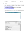
2) Start the MUSEcontrol program and select the item “Firmware Update” to update the device via
USB.
3) in the new “Firmware” window click on BROWSE to read the current firmware:
12/6/2013
26
User’s Manual
395 Mini Crate Series
W-Ie–Ne-R
Plein & Baus GmbH
A window will pop up asking for the path to the new firmware file:
4) To program the new firmware check both “Erase FW” and check “Erase BL”!!! and click on
OK,
When finished the above shown text will appear. Hit CANCEL to exit the programming window and
close MUSEcontrol.
In case programming seems to hang (message “program is not responding”) leave it running, it
may finish programming and just not be responding during that period!
12/6/2013
27