1
MeshBee®
Open Source ZigBee RF Module
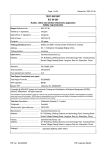
User's Manual
© 2014 Seeed Technology Inc. All rights reserved
www.seeedstudio.com
1
Doc Version
v0.1
Date
2014/04/28
Author
Remark
Created
2
Table of Contents
Table Of Contents
Overview ......................................................................................................................... 4
About this document ....................................................................................... 4
Introduction ..................................................................................................... 4
Acronyms and Abbreviations .......................................................................... 5
1. Key Features ................................................................................................................ 6
1.1 Physical features: ...................................................................................... 6
1.2 Operation features: .................................................................................... 6
2. Pin definition ............................................................................................................... 7
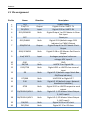
2.1 Pin assignment .......................................................................................... 8
3. Operation Mode .......................................................................................................... 9
3.1 AT mode ............................................................................................................ 9
3.2 API Mode ........................................................................................................ 10
3.3 MCU Mode ..................................................................................................... 10
3.4 Data Mode ....................................................................................................... 11
4. AT commands ............................................................................................................ 12
4.1 Node information commands .................................................................. 12
4.2 Data transmit commands ......................................................................... 13
4.3 Network formation commands ............................................................... 14
4.4 OTA commands ....................................................................................... 16
5. API frame .................................................................................................................. 18
5.1 Structure of API Frame ........................................................................... 18
6. AUPS Function list .................................................................................................... 23
6.1 Set run-time parameters .......................................................................... 23
6.2 Send RF data ........................................................................................... 24
6.3 Suli API ................................................................................................... 24
Appendix a: AT command index ................................................................................... 32
3
Overview
Overview
About this document
This manual gives a single point of reference for information relating to the MeshBee.
Including:
Chapt1: Key features;
Chapt2: Pin definition;
Chapt3: Operation mode;
Chapt4: AT commands;
Chapt5: API frames;
Chapt6: Functions that AUPS can call
Information shown in this document is all based on the firmware v1003. The manual
should be used as a reference resource throughout MeshBee application development. It does
not provide in-depth introduction of the MeshBee programming. Please refer to the MeshBee
CookBook(MB_2014_D02) for further references on the firmware architecture and
programming issue.
Introduction
MeshBee® is a 2.4 GHz wireless zigbee RF module together with high level open source
software driven by community. It uses microchip JN516x from NXP that enables several
different standards-based zigbee mesh networking. User can easily and cost-effectively
integrate ZigBee functionality into target project. Our factory firmware supports latest fully
Zigbee Pro stack.
MeshBee® is the best choice to make your connected thing.
4
Overview
Acronyms and Abbreviations
AUPS: Arduino-ful user programming space
SPM: Stream processing machine
CMI: Communication interface
ADS: Airport data server
UDS: Uart data server
HAL: Hardware abstract layer
SULI: Seeed Unified Library Interface
API: Application programming interface
MCU: Microcontroler
JenOS: Jennic operating system
5
Features
1. Key Features
1.1 Physical features:
1.2 Operation features:
1)
Range: Indoor/Urban: up to 30m;
Outdoor line-of-sight: up to 100m;
1)
Easy-to-Use Serial Interface and rich
extendable ports;
2)
Receiver Sensitivity: -95dBm;
2)
3)
Working Frequency: unlicensed
2.4GHz band;
Communication type: Point to Point,
Start Network , Mesh Network;
3)
Data Transmission Rate: 4800, 9600,
19200, 38400, 57600, 115200 (bps);
Support for OTA(upgrade firmware
over the air);
4)
Programmable 32-bit RISC CPU:
32M clock, 256KB Flash, 32KB RAM,
4KB EEPROM;
Easy-to-Use AT Command: Setup
ZigBee network, set Serial Baud Rate,
etc;
5)
API configuration and control mode;
6)
Arduino-ful user programming
space;
7)
Open source hardware and
firmware;
4)
5)
6)
Socket compatible with the Xbee, so
you can plug it into any Xbee socket
as a quick replacement
Open
Community
MeshBee
6
Features
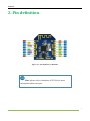
2. Pin definition
Figure 2.1: Pin definition of MeshBee
Note: please refer to datasheet of JN516x for more
information about each pin.
7
Features
2.1 Pin assignment
Pin No
Name
Direction
Description
1
2
3
4
3V3
D14/TX1
D15/RX1
DO1/SPIMISO
—
Output
Input
Both
5
6
RST
D11/PWM1
—
Both
7
DO0/SPICLK
Output
8
D18/ SPIMOSI
Both
9
Vref/ ADC2
Input
10
11
12
GND
D6/TX0
D12/CTS0
—
Both
Both
13
D9
Both
14
15
D7/RX0
D10
Both
Both
16
RTS0
Both
17
D1/SPISEL2/ADC4
Both
18
D0/SPISEL1/ADC3
Both
19
20
D16/SCL
D17/SDA
Both
Both
Power supply
Digital IO14 or UART1 TX
Digital IO15 or UART1 RX
Digital Output 1 or SPI Master In Slave
Out Input
Reset pin
Digital IO11 (default usage: RSSI
Indicator) or PWM1 Output
Digital Output 0 or SPI Master Clock
Output
Digital IO 18 or SPI Master Out Slave In
Output
Analogue peripheral reference
voltage; ADC input 2
GND
UART0 TX or Digital IO6
Digital IO12 or UART0 clear to send
input
Digital IO 9 (default usage: Mesh Bee
ON/Sleep Indicator)
UART0 RX or Digital IO 7
Digital IO 10 (default usage: Network
Association Indicator)
Digital IO 13 or UART0 request to send
output
Digital IO 1; SPI Master Select Output
2; ADC input 4
Digital IO 0; SPI Master Select Output
1; ADC input 3
Digital IO 16 or I2C clock
Digital IO 17 or I2C data
8
Set Up
3. Operation Mode
MeshBee has four different types of mode: AT, API, DATA, MCU, illustrated in figure
below:
Figure 3.1: No matter which mode MeshBee works in, input “+++” can come back to AT command
mode.
3.1 AT mode
Mesh Bee communicates with outside through UART1 including data and command
communicating. The default setting of UART1 is: 115200 baud rate, data bits 8, parity none,
stop bit 1. “+++<CR>” can put Mesh Bee into AT mode. The mode switch is illustrated in
figure 3.1.
AT command can be classified into two types: register R/W AT and action AT.
The pattern of AT command is “ATXX[DDDD]<CR>” in which XX stands for the
register/action name and DDDD stands for the written value of a register. All letters’ case is
ignored.
Register R/W AT can operate a virtual register of Mesh Bee. Absence of DDDD means
reading the register value out and meanwhile ATXXDDDD means setting the register value
to DDDD.
Action AT can trigger a specific action. The execution of command may be immediate or
time-consuming.
9
Set Up
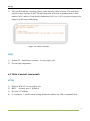
Syntax for sending AT commands:
Figure 3.2: syntax for AT commands
3.2 API Mode
API is simply a set of standard interfaces created to allow other MCU to interact with
MeshBee. For our purposes, API supports local operation and remote operation. For example,
a host application can send an “ATIO” frame to Coordinator A, A will set its GPIO when it
receives this frame. The most important thing to note is that APIs are specifically engineered
to enable MeshBee to talk efficiently to other MCU. The target of API-mode is to transmit
highly structured data quickly and reliably.
3.3 MCU Mode
In order to simplify the development of application for user, we create an Arduino-ful
user programming space(AUPS).
In AT mode, using “ATMC” to enter MCU mode, then the arduino_loop will be
executed periodically.
Write your own code in “ups_arduino_sketch.c”.
Example :
IO_T led_io;
int16 state = HAL_PIN_HIGH;
void arduino_setup(void)
{
setLoopIntervalMs(1000);
//set loop period
10
Set Up
suli_pin_init(&led_io, 9);
//init led
suli_pin_dir(&led_io, HAL_PIN_OUTPUT);
}
void arduino_loop(void)
{
suli_pin_write(&led_io, state);
//set led
if(state == HAL_PIN_HIGH)
state = HAL_PIN_LOW;
else
state = HAL_PIN_HIGH;
}
Note: In MCU mode, Uart1 is under the control of the
AUPS, user should not send API frame to MeshBee.
3.4 Data Mode
When operating in Data mode, the modules act as a serial line. All UART data received
through the UART1 is transmitted to a specified remote device.
To use a transparent connection, take the following steps:
1) Set unicast address:
ATDAxxx
2) Enter Data Mode:
ATDT
11
Set Up
4. AT commands
4.1 Node information commands
ATIF
1)
2)
3)
4)
Action AT,immediate execution,for any zigbee role.
Get node InFormation
ATIF command will print information of node including: supported AT commands, node’s
firmware version, node’s zigbee short address, node’s MAC address, node’s radio channel,
node’s zigbee role, etc.
Example:
Figure 3.3: ATIF screen shot
ATLA
1)
2)
Action AT, time-consuming execution, for any zigbee role
List All nodes within the network
12
Set Up
3)
ATLA will broadcast a topology query packet into the whole network. The node that’s
still alive may response to that. The querying node will print responding nodes’ short
address, MAC address, Link-Quality-Indication (LQI), etc. LQI is a positive integer, the
bigger LQI the better link quality.
Figure 3.4: ATLA screen shot
ATQT
1)
2)
Action AT, immediate execution, for any zigbee role
Get on-chip temperature.
4.2 Data transmit commands
ATTM
1)
2)
3)
4)
Register R/W AT, for any zigbee role
Bits:1, decimal, max:1, default:0
Set node’s TX Mode
0 - broadcast, 1- unicast (need setting destination address by ATDA command first).
13
Set Up
ATDA
1)
2)
3)
4)
5)
Register RW AT, for any zigbee role
Bits:4, hex, max: ffff, default:0000
Set node’s unicast destination address
This address will also be used as the OTA target address, means that this destination
address will be used for ATOT and ATOS command. It has a pattern of HHHH that is 4
bits of HEX number ignoring case.
Example:ATDA14ad<CR>
ATBR
1)
2)
3)
4)
5)
Register R/W AT, for any zigbee role
Bits:1, decimal, max:5, default:5
Set UART1’s Baud Rate
0- 4800, 1-9600, 2-19200, 3-38400, 4-57600, 5-115200.
Example: ATBR5<CR>
4.3 Network formation commands
ATPA
1)
2)
3)
4)
Register RW AT, for any zigbee role but with different effect.
Bits:1, decimal, max:1, default:0
Set node’s Power up Action
The node’s default power-up behavior is restoring the last network state before power
down. But when setting PA register to 1 and then reboot, the node will not restore the last
network. In this case, coordinator node will re-create a network and router/End device
will re-scan the network. The PA register will be cleared to 0 after reboot.
14
Set Up
ATRS
1)
2)
3)
Action AT, time-consuming execution, for router/End device
Re-Scan network
The scanning process will take a while and you can use ATLN command to monitor the
scan result. If node finds nothing after a long time scanning, retry ATRS command or reset
Mesh Bee. The node will automatically join the first found network when AJ register has a
value of 1.
ATLN
1)
2)
3)
Action AT, immediate execution, for router/End device
List Network scanned
The index value will be used by ATJN command.
ATJN
1)
2)
3)
4)
Register R/W AT, for router/End device
Bits:1, decimal, max:8, default:0
Join a Network with specific index
ATJN command is also an action trigger command. The node will join the network
specified by the index of ATLN output. ATJN will return error when the node’s already in
that network.
ATAJ
1)
2)
3)
4)
Register RW AT, for router/End device
Bits:1, decimal, max:1, default:1
Whether Auto Join network scanned
If AJ register has a value of 1, the node will automatically join the first network scanned
after ATRS command or power up with PA register equals to 1.
15
Set Up
4.4 OTA commands
ATOT
1)
2)
3)
Action AT, immediate execution, for coordinator
OTA Trigger
Non-coordinator nodes can upgrade firmware over-the-air. This is called OTA. ATOT
command will trigger the OTA upgrade download of a destination node. OTA architecture
consists of OTA server and client. Coordinator will be the server side and router/End
device is the client side. To OTA a client node, you should firstly enter the AT mode on
server side and set the unicast destination address (DA register) to the short address of the
client node, and then execute the ATOT command. And now trace serial port (usually
UART0) will print some information about OTA process if trace is enabled. After
downloading all image blocks which are saved in the external Flash, the client node will
trigger the upgrade process automatically. The process is: mark the internal firmware
invalid, then reboot, and then the bootloader will copy the new image from the external
Flash into the internal Flash, and then run the new firmware.
Figure 3.5: ATOT screen shot
ATOR
1)
2)
3)
4)
Register RW AT, for coordinator
Bits:5, decimal, max:60000, default:1000
OTA block request Rate
Set the interval of two image block requests. The value’s unite is milliseconds. The
smaller, the faster.
16
Set Up
ATOA
1)
2)
3)
4)
Action AT, immediate execution, for coordinator
OTA Abort
Abort the OTA downloading process of a specific node specified by the DA register.
Example:
Figure 3.6: ATOA screen shot
ATOS
1)
2)
3)
Action AT, time-consuming execution, for coordinator
Query OTA Status
Query the status of the OTA downloading process of a specific node specified by the DA
register.
Figure 3.7: ATOS screen shot
17
Set Up
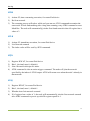
5. API frame
5.1 Structure of API Frame
Every transfer of information requires a protocol. We defined the API frame like
this(structure was defined in firmware_at_api.h):
Figure 5.1: API Frame structure
5.1.1 API structure types
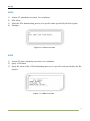
API_LOCAL_AT_REQ
API identifier value: 0x08
These packet types are useful only if the host wants to send commands to its local
MeshBee. You don’t need to specify the unicast address.
Figure 5.2: local AT require
Frame ID: To Identifies the UART data frame for the host to correlate with a subsequent ACK
(acknowledgement).
AT index Num: Index of the AT commands.
Parameter value: Parameter value to be set.
18
Set Up
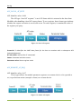
API_LOCAL_AT_RESP
API identifier value: 0x88
The API type “local AT response” is an ACK frame which is returned to the host from
MeshBee after handling a local AT request frame. To set a register, these frame types indicate
whether the request execution is successful or not. To read a register, it contains the value of
the register you query.
Figure 5.3: local AT response
Frame ID: To Identifies the UART data frame for the host to correlate with a subsequent ACK
(acknowledgement).
AT index Num: Index of the AT commands.
Status: Command execution status.
Parameter value: Return register value.
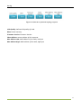
API_REMOTE_AT_REQ
API identifier value: 0x17
These types allows for module parameter registers on a remote device to be queried or
set, or perform an action (example: reboot) on a remote device.
Figure 5.4: remote AT require
19
Set Up
Frame ID: To Identifies the UART data frame for the host to correlate with a subsequent ACK
(acknowledgement).
Option:
[8:0]:ACK Mode, 0 with ACK; 1 without ACK.
[8:1]:Cast Mode,0 unicast; 1 broadcast.
AT index Num: Index of the AT commands.
Parameter value: Parameter value to be set.
Unicast Address: Set to the 16- bit network address of the remote.
API_REMOTE_AT_RESP
API identifier value: 0x97
The API type “remote AT response” is an ACK frame which is returned to the host from
the remote node after handling a remote AT request frame.
Figure 5.5: remote AT response
Frame ID: To Identifies the UART data frame for the host to correlate with a subsequent ACK
(acknowledgement).
AT index Num: Index of the AT commands.
Status: Command execution status.
Parameter value: Return register value.
Unicast Address: 16- bit network address of the remote.
API_DATA_PACKET
API identifier value: 0x02
The API type “data packet” is a user data frame. This request message will cause the
module to send RF Data as an RF Packet.
20
Set Up
Figure 5.6: Data packets TX require
Frame ID: To Identifies the UART data frame for the host to correlate with a subsequent ACK
(acknowledgement).
Option:
[8:0]:ACK Mode, 0 with ACK; 1 without ACK.
[8:1]:Cast Mode,0 unicast; 1 broadcast.
Data length: the length of data payload.
Parameter value: Data value.
Unicast Address: Set to the 16- bit network address of the remote.
API_TOPO_REQ
API identifier value: 0xfb
This API type allows module to query the network topology.
Figure 5.7: Structure of network Topo Require
API_TOPO_RESP
API identifier value: 0x6b
In response to an “API_TOPO_REQ” message, the module will send a response
message.
21
Set Up
Figure 5.8: Structure of network topology response
Link Quality: Indicate link quality of node.
Dbm: Power intensity.
Firmware Version: Firmware Version.
Short Address: source address of this response.
Mac Address Low: MAC address of the node, low byte.
Mac Address High: MAC address of the node, high byte.
22
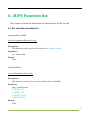
6. AUPS Function list
This chapter contains the information of functions that AUPS can call.
6.1 Set run-time parameters
setLoopIntervalMs
void setLoopIntervalMs(uint32 ms);
Description:
This function can be used to set the period of “arduino_Loop()”.
Parameter:
ms : millisecond
Return:
None
setNodeState
void setNodeState(uint32 state);
Description:
This function can be used to set the working state of MeshBee.
Parameter:
state : working state
E_MODE_AT
E_MODE_API
E_MODE_DATA
E_MODE_MCU
Return:
None
23
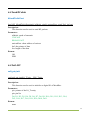
6.2 Send RF data
bSendToAirPort
bool API_bSendToAirPort(uint16 txMode, uint16 unicastDest, uint8 *buf, int len);
Description:
This function can be used to send RF packets.
Parameter:
txMode: mode of transmit
UNICAST
BROADCAST
unicastDest: short address of unicast
buf: the pointer of data
len: length of the data
Return:
OK
ERR
6.3 Suli API
suli_pin_init
void suli_pin_init(IO_T *pio,
PIN_T pin);
Description:
This function can be used to initialize a digital IO of MeshBee.
Parameter:
pio: pointer of the IO_T entity
pin: pin No
D0, D1, D2, D3, D4, D5, D6, D7, D8, D9, D10, D11, D12, D13, D14,
D15, D16, D17, D18, D19, D20, DO0, DO1.
Return:
none
24
suli_pin_dir
void suli_pin_dir(IO_T *pio, DIR_T dir);
Description:
This function can be used to set direction of digital IO.
Parameter:
pio: pointer of the IO_T entity
dir: direction
HAL_PIN_INPUT
HAL_PIN_OUTPUT
Return:
none
suli_pin_write
void suli_pin_write(IO_T *pio, int16 state);
Description:
This function can be used to write a digital IO.
Parameter:
pio: pointer of the IO_T entity
state: state of IO
HAL_PIN_LOW
HAL_PIN_HIGH
Return:
none
suli_pin_read
int16 suli_pin_read(IO_T *pio);
Description:
25
This function can be used to read a digital IO.
Parameter:
pio: pointer of the IO_T entity
Return:
state: state of IO
HAL_PIN_LOW
HAL_PIN_HIGH
suli_analog_init
void suli_analog_init(ANALOG_T * aio, PIN_T pin);
Description:
This function can be used to initialize an analog pin.
Parameter:
aio: pointer of the ANALOG_T entity
pin: pin No
A1 : ADC1
A2 : ADC2
A3 : ADC3
A4 : ADC4
TEMP: On-chip temperature ADC
VOL : On-chip voltage ADC
Return:
none
suli_analog_read
int16 suli_analog_read(ANALOG_T *aio);
Description:
This function can be used to read the ADC value.
Parameter:
aio: pointer of the ANALOG_T entity
26
Return:
ADC value
suli_i2c_init
void suli_i2c_init(void * i2c_device);
Description:
This function can be used to initialize I2C of MeshBee (D16, D17).
Parameter:
i2c_device: any dummy value
Return:
none
suli_i2c_write
uint8 suli_i2c_write(void * i2c_device, uint8 dev_addr, uint8 *data, uint8 len);
Description:
This function can be used to write a buff to I2C.
Parameter:
i2c_device: any dummy value
dev_addr: device address
data: data array
len: length of the data
Return:
The number of bytes already been written
suli_i2c_read
uint8 suli_i2c_read(void *i2c_device, uint8 dev_addr, uint8 *buff, uint8 len);
27
Description:
This function can be used to read a buff from I2C.
Parameter:
i2c_device: any dummy value
dev_addr: device address
data: pointer of data array
len: length of the data
Return:
The number of bytes already been read
suli_uart_init
void suli_uart_init(void * uart_device, int16 uart_num, uint32 baud);
Description:
This function can be only used to initialize uart1of MeshBee. Because uart0 is under the
control of the system.
Parameter:
uart_device: any dummy value
uart_num: any dummy value
baud: baud rate
4800
9600
19200
38400
57600
115200
Return:
none
suli_uart_send
void suli_uart_send(void * uart_device, int16 uart_num, uint8 *data, uint16 len);
Description:
28
This function can be only used to send data through uart1.
Parameter:
uart_device: any dummy value
uart_num: any dummy value
data: pointer of the data array
len: length of the data
Return:
none
suli_uart_send_byte
void suli_uart_send_byte(void *uart_device, int16 uart_num, uint8 data);
Description:
This function can be only used to send one byte through uart1.
Parameter:
uart_device: any dummy value
uart_num: any dummy value
data: data byte
Return:
none
suli_uart_write_float
void suli_uart_write_float(void *uart_device, int16 uart_num, float data, uint8 prec);
Description:
This function can be only used to send float data through uart1.
Parameter:
uart_device: any dummy value
uart_num: any dummy value
data: float data
Return:
none
29
suli_uart_write_int
void suli_uart_write_int(void *uart_device, int16 uart_num, int32 num);
Description:
This function can be only used to send int data through uart1.
Parameter:
uart_device: any dummy value
uart_num: any dummy value
num: int value
Return:
none
suli_uart_printf
void suli_uart_printf(void *uart_device, int16 uart_num, const char *fmt, ...) ;
Description:
This function can be only used to send formatted string to uart1.
Parameter:
uart_device: any dummy value
uart_num: any dummy value
fmt: format of string
Return:
none
suli_uart_read_byte
uint8 suli_uart_read_byte(void * uart_device, int16 uart_num);
Description:
30
This function can be only used to read a byte from uart1.
Parameter:
uart_device: any dummy value
uart_num: any dummy value
Return:
Returned byte
suli_uart_readable
uint16 suli_uart_readable(void * uart_device, int16 uart_num);
Description:
This function can be only used to judge if uart1 is readable.
Parameter:
uart_device: any dummy value
uart_num: any dummy value
Return:
The number of bytes which can be read
31
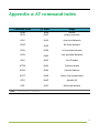
Appendix a: AT command index
Command Name
ATRB
ATPA
Note:
AT Index
0x30
0x32
usage
reboot
power up action
ATAJ
0x34
Auto Join Network
ATRS
0x36
Re-Scan Network
ATLN
0x38
List scanned network
ATJN
0x40
Join specified Network
ATLA
0x42
List All nodes
ATTM
0x44
Transmit mode
ATDA
0x46
Unicast Address
ATQT
0x48
Query Chip temperature
ATIO
0x50
Handle IOs
ATIF
0x52
Node information
v1003 firmware compatible
32
STU
Copyright (c) 2014 Seeed Technology Inc.
F5, Bldg 8, Shiling Industrial Park,
Xinwei, #32 Tongsha Road,
Xili Town, Nanshan Dist.
Shenzhen 518055 China
+86 755 33552591
www.seeedstudio.com
33