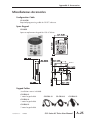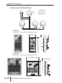
1
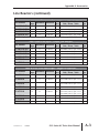
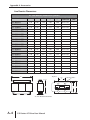
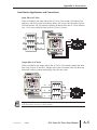
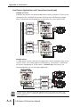
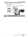
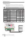
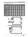
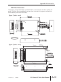
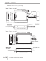
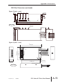
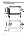
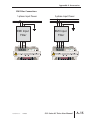
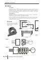
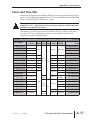
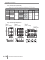
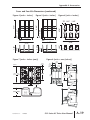
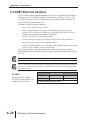
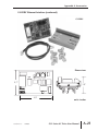
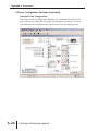
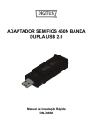
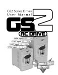
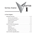
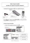
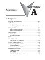
ACCESSORIES
APPENDIX
A
In This Appendix...
Accessories Part Numbering . . . . . . . . . . . . . . . . . . . . . . . . . .A–2
Line Reactors . . . . . . . . . . . . . . . . . . . . . . . . . . . . . . . . . . . . .A–2
Line Reactor Dimensions . . . . . . . . . . . . . . . . . . . . . . . . . . . . . . .A–4
Line Reactor Applications and Connections . . . . . . . . . . . . . . . . .A–5
Braking Resistors . . . . . . . . . . . . . . . . . . . . . . . . . . . . . . . . . . .A–8
Braking Resistor Connections . . . . . . . . . . . . . . . . . . . . . . . . . . .A–8
Braking Resistor Dimensions . . . . . . . . . . . . . . . . . . . . . . . . . . . .A–9
EMI Input Filters . . . . . . . . . . . . . . . . . . . . . . . . . . . . . . . . . .A–10
EMI Filter Dimensions . . . . . . . . . . . . . . . . . . . . . . . . . . . . . . . .A–11
EMI Filter Connections . . . . . . . . . . . . . . . . . . . . . . . . . . . . . . .A–15
RF Filters . . . . . . . . . . . . . . . . . . . . . . . . . . . . . . . . . . . . . . . .A–16
Fuses and Fuse Kits . . . . . . . . . . . . . . . . . . . . . . . . . . . . . . . .A–17
Fuses and Fuse Kits Dimensions . . . . . . . . . . . . . . . . . . . . . . . .A–18
GS-EDRV Ethernet Interface . . . . . . . . . . . . . . . . . . . . . . . . .A–20
GS Drive Configuration Software . . . . . . . . . . . . . . . . . . . . .A–22
System Requirements . . . . . . . . . . . . . . . . . . . . . . . . . . . . . . . .A–22
Software Configuration Methods . . . . . . . . . . . . . . . . . . . . . . .A–22
Miscellaneous Accessories . . . . . . . . . . . . . . . . . . . . . . . . . . .A–25
Configuration Cable . . . . . . . . . . . . . . . . . . . . . . . . . . . . . . . . .A–25
Spare Keypad . . . . . . . . . . . . . . . . . . . . . . . . . . . . . . . . . . . . . .A–25
Keypad Cables . . . . . . . . . . . . . . . . . . . . . . . . . . . . . . . . . . . . .A–25
Communication Distribution Blocks . . . . . . . . . . . . . . . . . . . . .A–26
Appendix A: Accessories
Accessories Part Numbering
With the exception of EMI Filters, RF Filters, and some Line Reactors, GS2 Series
accessory part numbers incorporate the part numbers of the AC Drives for which they
are compatible. Each accessory part number begins with the AC Drive series and
rating. This is followed by an accessory code, and, when applicable, a description
code. The accessory part numbering scheme is shown below.
GS - 23P0 - LR - 3PH
Description Code (optional)
1PH: Single phase 3PH: Three phase ENC: Enclosure
Blank: For reactor, check specific part # to determine phase
Accessory Code
BR: Braking resistor FKIT: Fuse Kit
FUSE: Replacement fuses for FKIT LR: Line reactor
Drive Rating (See Drive P/N description)
BZL: Bezel CBL: Cable DBU: Dynamic Brake Unit
EDRV: Ethernet board FB: Feedback board
KPD: Keypad RS: Recommended Standard
Drive Series
GS: All GS and DURApulse Series Drives
GS1: GS1 Series GS2: GS2 Series
GS3: DURApulse Series
Line Reactors
Input line reactors protect the AC drive from transient overvoltage conditions
typically caused by utility capacitor switching. Input line reactors also reduce the
harmonics associated with AC drives, and are recommended for all installations.
Output line (load) reactors protect the motor insulation against AC drive short
circuits and IGBT reflective wave damage, and also allow the motor to run cooler
by “smoothing” the motor current waveform. They are recommended for
operating “non-inverter-duty” motors, and for any motors when the length of
wiring between the AC drive and motor exceeds 75 feet.
115V Single Phase Input Line Reactors*
Part Number
GS-10P2-LR
GS-10P5-LR
GS-11P0-LR
Rated
Watt
Impedance Inductance
Amps
Loss
GS2 Drive Model and
Side / Phase / Volts
Drive
hp
18
3%
0.80 mH
19
GS2-10P2 (input) / 1ph / 115V
0.25
25
3%
0.50 mH
23
GS2-10P5 (input) / 1ph / 115V
0.5
35
3%
0.40 mH
36
GS2-11P0 (input) / 1ph / 115V
1
*NOTE: Single phase line reactors should NOT be installed on the output side of the AC drive.
A–2
GS2 Series AC Drive User Manual
Appendix A: Accessories
Line Reactors (continued)
230V Single Phase Input Line Reactors*
Rated
Watt
Impedance Inductance
Amps
Loss
Part Number
GS-20P5-LR-1PH
GS-21P0-LR-1PH
GS-22P0-LR-1PH
GS-23P0-LR-1PH
GS2 Drive Model and
Side / Phase / Volts
Drive
hp
8
3%
6.50 mH
13
GS2-20P5 (input) / 1ph / 230V
0.5
12
3%
6.50 mH
13
GS2-21P0 (input) / 1ph / 230V
1
18
3%
3.00 mH
25
GS2-22P0 (input) / 1ph / 230V
2
35
3%
2.50 mH
26
GS2-23P0 (input) / 1ph / 230V
3
*NOTE: Single phase line reactors should NOT be installed on the output side of the AC drive.
230V Three Phase Input / Output Line Reactors
Rated
Watt
Impedance Inductance
Amps
Loss
Part Number
GS-20P5-LR-3PH
GS-21P0-LR-3PH
GS-22P0-LR-3PH
GS-23P0-LR-3PH
GS-25P0-LR
GS-27P5-LR
GS2 Drive Model and
Side / Phase / Volts
Drive
hp
4
3%
6.50 mH
13
GS2-20P5 (in/out) / 3ph / 230V
0.5
4
3%
3.00 mH
7
GS2-21P0 (in/out) / 3ph / 230V
1
8
3%
1.50 mH
11
GS2-22P0 (in/out) / 3ph / 230V
2
12
3%
1.30 mH
23
GS2-23P0 (in/out) / 3ph / 230V
3
18
3%
0.80 mH
19
GS2-25P0 (in/out) / 3ph / 230V
5
25
3%
0.50 mH
23
GS2-27P5 (in/out) / 3ph / 230V
7.5
460V & 575V Three Phase Input / Output Line Reactors
Part Number
Rated
Watt
Impedance Inductance
Amps
Loss
GS2 Drive Model and
Side / Phase / Volts
Drive
hp
GS2-41P0 (in/out) / 3ph / 460V
1
GS2-42P0 (in/out) / 3ph / 460V
GS2-53P0 (in/out) / 3ph / 575V
GS2-43P0 (in/out) / 3ph / 460V
GS2-55P0 (in/out) / 3ph / 575V
2
3
3
5
GS-41P0-LR
2
3%
12.0 mH
7
GS-42P0-LR
4
3%
6.50 mH
13
GS-43P0-LR
8
3%
5.00 mH
31
GS-45P0-LR
8
3%
3.00 mH
25
GS2-45P0 (in/out) / 3ph / 460V
5
GS-47P5-LR
12
3%
2.50 mH
26
GS2-47P5 (in/out) / 3ph / 460V
GS2-57P5 (in/out) / 3ph / 575V
GS2-5010 (in/out) / 3ph / 575V
7.5
7.5
10
GS-4010-LR
GS-51P0-LR
GS-52P0-LR
18
3%
1.50 mH
29
GS2-4010 (in/out) / 3ph / 460V
10
2
3%
20.0 mH
9
GS2-51P0 (in/out) / 3ph / 575V
1
4
3%
9.10 mH
15
GS2-52P0 (in/out) / 3ph / 575V
2
1st Ed. Rev. C
12/2006
GS2 Series AC Drive User Manual
A–3
Appendix A: Accessories
Line Reactor Dimensions
AC Line Reactor Dimensions (inches)
Part Number
GS-10P2-LR
GS-10P5-LR
GS-11P0-LR
GS-20P5-LR-1PH
GS-20P5-LR-3PH
GS-21P0-LR-1PH
GS-21P0-LR-3PH
GS-22P0-LR-1PH
GS-22P0-LR-3PH
GS-23P0-LR-1PH
GS-23P0-LR-3PH
GS-25P0-LR
GS-27P5-LR
GS-41P0-LR
GS-42P0-LR
GS-43P0-LR
GS-45P0-LR
GS-47P5-LR
GS-4010-LR
GS-51P0-LR
GS-52P0-LR
H
W
D
Mtg. D
Mtg. W
Mtg Slot
Hole Size
Weight
(lbs)
4.80
6.00
3.30
2.09
2.00
0.28 x 0.63
7
5.70
6.00
3.09
2.09
3.00
0.28 x 0.63
7
5.70
6.00
3.34
2.34
3.00
0.28 x 0.63
9
3.40
4.40
2.83
1.77
1.44
0.28 x 0.63
2.80
3.40
4.40
2.83
1.77
1.44
0.28 x 0.63
2.80
3.40
4.40
2.83
1.77
1.44
0.28 x 0.63
2.80
3.40
4.40
2.83
1.77
1.44
0.28 x 0.63
2.30
3.40
4.40
2.83
1.77
2.00
0.28 x 0.63
3.10
3.40
4.40
2.83
1.77
2.00
0.28 x 0.63
2.80
4.80
6.00
3.30
2.09
2.00
0.28 x 0.63
7.50
3.40
4.40
2.83
1.77
2.00
0.28 x 0.63
2.90
4.80
6.00
3.30
2.09
2.00
0.28 x 0.63
7.10
5.70
6.00
3.09
2.09
3.00
0.28 x 0.63
7.00
3.40
4.40
2.83
1.77
1.44
0.28 x 0.63
2.30
3.40
4.40
2.83
1.77
1.44
0.28 x 0.63
2.80
3.40
4.40
3.39
2.39
2.00
0.28 x 0.63
4.30
3.40
4.40
2.83
1.77
2.00
0.28 x 0.63
3.10
4.80
6.00
3.30
2.09
2.00
0.28 x 0.63
7.50
4.80
6.30
3.55
2.34
2.00
0.28 x 0.63
9.10
3.40
4.40
2.83
1.77
1.44
0.28 x 0.63
3
3.40
4.40
3.33
2.37
1.44
0.28 x 0.63
3
W
Top View
MTG
W
H
AC Line Reactor Dimensions
A–4
GS2 Series AC Drive User Manual
Label
Mounting Holes
MTG
D
D
Appendix A: Accessories
Line Reactor Applications and Connections
Input Side of AC Drive
When installed on the input side of the AC Drive, line reactors will reduce line
notching, and limit current and voltage spikes and surges from the incoming line.
The line reactors will also reduce harmonic distortion from the AC Drive onto the
line. Units are installed in front of the AC Drive as shown.
C1
C2
L3
T3
B1
B2
T2
L2
T1
A1
A2
L1
Output Side of AC Drive
When installed on the output side of the AC Drive, line reactors protect the drive
from short circuits at the load. Voltage and current waveforms from the drive are
enhanced, reducing motor overheating and noise emissions.
T3
C1
C2
T2
B1
B2
T1
A1
A2
Single-phase line reactors should NOT be installed on the output of the AC Drive. Use
only three-phase reactors on drive outputs.
1st Ed. Rev. C
12/2006
GS2 Series AC Drive User Manual
A–5
Appendix A: Accessories
Line Reactor Applications and Connections (continued)
Multiple AC Drives
Individual line reactors are recommended when installing multiple AC Drives on the
same power line. Individual line reactors eliminate cross-talk between multiple
drives, and provide isolated protection for each drive for its own specific load.
C1
C2
L3
T3
B1
B2
T2
L2
T1
A1
A2
L1
C1
C2
L3
B1
B2
L2
T3
T2
T1
A1
A2
L1
Multiple Motors
A single reactor can be used when the application calls for multiple motors on the
same AC Drive, if the motors operate simultaneously. The reactor is sized based
on the total horsepower of all the motors. Overload relays (not shown) are
recommended for use in multi-motor applications.
T3
C1
C2
T2
B1
B2
T1
A1
A2
A single reactor should be used with multiple motors ONLY when the motors will
operate simultaneously. OVERLOAD RELAYS are recommended for use in multiple
motor applications.
A–6
GS2 Series AC Drive User Manual
Appendix A: Accessories
Line Reactor Applications and Connections (continued)
Single-Phase Applications
Some of the line reactors are listed for use with single-phase input power. Follow
the connection diagram shown below. Make sure that terminals B1 and B2 are
properly insulated before any connections are made.
C1
C2
L2
T3
B1
T2
B2
T1
A1
A2
L1
WARNING: Please ensure that you properly insulate terminals B1 and B2 before making
any connections to single-phase power.
1st Ed. Rev. C
12/2006
GS2 Series AC Drive User Manual
A–7
Appendix A: Accessories
Braking Resistors
Braking resistors are used to increase the control torque of the AC Drive, for
frequently repeated ON-OFF cycles of the AC Drive, or for decelerating a load
with large inertia.
The use of braking resistors with GS2 Series AC drives requires no parameter setup. The
AC drive automatically senses the presence of braking resistors.
Braking Resistor Specifications
Part Number
GS-20P5-BR
GS-21P0-BR
GS-22P0-BR
GS-23P0-BR
GS-25P0-BR
GS-27P5-BR
GS-41P0-BR
GS-42P0-BR
GS-43P0-BR
GS-45P0-BR
GS-47P5-BR
GS-4010-BR
Quantity
Drive Model
& Wiring
GS2-10P2, GS2-10P5, GS2-20P5
1
GS2-11P0, GS2-21P0
1
GS2-22P0
1
GS2-23P0
1
GS2-25P0
1
GS2-27P5
1
GS2-41P0
1
GS2-42P0, GS2-51P0, GS2-52P0
1
2 in parallel GS2-53P0, GS2-55P0, GS2-57P5
GS2-43P0
1
GS2-45P0
1
GS2-47P5
1
GS2-4010
1
GS2-5010
2 in series
Braking
Duty
Ohms Watts
Torque
Cycle
270%
200⏲
80
10%
125%
200⏲
80
10%
125%
100⏲
300
10%
125%
70⏲
300
10%
125%
40⏲
400
10%
125%
30⏲
500
10%
125%
750⏲
80
10%
125%
400⏲
300
10%
125%
250⏲
300
10%
125%
150⏲
400
10%
125%
100⏲
500
10%
125%
75⏲
1000
10%
Braking Resistor Connections
Braking
Resistor
B1 B2
A–8
GS2 Series AC Drive User Manual
Appendix A: Accessories
Braking Resistor Dimensions
Braking Resistor Dimensions (mm)
Part Number
Figure
L1
L2
H
D
W
Maximum
weight (g)
1
140
125
20
5.3
60
160
1
140
125
20
5.3
60
160
1
215
200
30
5.3
60
750
1
215
200
30
5.3
60
750
1
265
250
30
5.3
60
930
2
335
320
30
5.3
60
1100
1
140
125
20
5.3
60
160
1
215
200
30
5.3
60
750
1
215
200
30
5.3
60
750
1
265
250
30
5.3
60
930
2
335
320
30
5.3
60
1100
2
400
385
50
5.3
100
2800
GS-20P5-BR
GS-21P0-BR
GS-22P0-BR
GS-23P0-BR
GS-25P0-BR
GS-27P5-BR
GS-41P0-BR
GS-42P0-BR
GS-43P0-BR
GS-45P0-BR
GS-47P5-BR
GS-4010-BR
Figure 1
W+
- 0.5
D+
- 0.5
L2 +
-- 2
RING TERMINAL
H+
- 0.5
150±2
L1+
-2
L2+
-2
D+
- 0.5
W+
- 0.5
Figure 2
H+
- 0.5
TERMINAL: 2t x 125 x Ø63
L1+
-2
1st Ed. Rev. C
12/2006
GS2 Series AC Drive User Manual
A–9
Appendix A: Accessories
EMI Input Filters
The EC Declaration of Conformity for the GS2 Series AC Drives was completed in
conjunction with EMI Filters listed below.
CE compliance requires the use of EMI filters; not available for 575V drives.
EMI Input Filter Specifications
EMI Filter
20DRT1W3S
32DRT1W3C
not available
AC Drive Model
/ Input Phase
Filter Input Rating
Filter Dimensions
GS2-10P2 / 1ph
GS2-10P5 / 1ph
GS2-11P0 / 1ph
GS2-20P5 / 1ph
GS2-21P0 / 1ph
GS2-22P0 / 1ph
250V, 1-phase, 20A
Figure 1
GS2-23P0 / 1ph
250V, 1-phase, 32A
Figure 2
GS2-20P5 / 3ph
n/a
10TDT1W4C *
GS2-21P0 / 3ph
GS2-22P0 / 3ph
250V, 3-phase, 10A
Figure 3
26TDT1W4C *
GS2-23P0 / 3ph
250V, 3-phase, 26A
Figure 4
40TDS4W4B
GS2-25P0 / 3ph
GS2-27P5 / 3ph
250V, 3-phase, 40A
Figure 5
11TDT1W4S
GS2-41P0 / 3ph
GS2-42P0 / 3ph
GS2-43P0 / 3ph
480V, 3-phase, 11A
Figure 6
17TDT1W44
GS2-45P0 / 3ph
GS2-47P5 / 3ph
480V, 3-phase, 17A
Figure 7
GS2-4010 / 3ph
480V, 3-phase, 26A
Figure 8
26TDT1W4B4
not available
GS2-5xxx
n/a
* EMI filters 10TDT1W4C and 26TDT1W4C do not mount underneath GS2 drives.
A–10
GS2 Series AC Drive User Manual
Appendix A: Accessories
EMI Filter Dimensions
These filters, except 10TDT1W4C and 26TDT1W4C, mount between the drive and the subpanel. The filters have threaded holes on their front surface for this purpose, and the drives
mount directly to the front of the filters.
POWER-IN
Figure 1 [units = mm]
20DRT1W3S
Figure 2 [units = mm]
A
_ 2.0
306.0 +
M5X0.8(4x)
10.0
C
POWER-IN
_1.0
122.0 +
101 AWG 12 BLUE
101 AWG 12 BLACK
101 AWG 12 G/Y
F
D
E
_ 2.0
153.0 +
R3.0
_10.0
250.0 +
R4.5
_ 2.0
50.0 +
B
_1.0
284.0 +
32DRT1W3C
H
_ 1.0
25.0 +
o8.0(4x)
G
_1.0
284.0 +
1st Ed. Rev. C
12/2006
GS2 Series AC Drive User Manual
A–11
Appendix A: Accessories
EMI Filter Dimensions (continued)
Figure 3 [units = mm (in)]
100.0±1.0 (3.93±0.0393)
125.0±2.0(4.92±0.0787)
237.0 ± 2.0 (9.33 ± 0.0787)
10.0 (.39)
R2.5
1015 AWG18
R4.0
BLUE
BLACK
BROWN
G/Y
200 ± 10 (7.9 ± .39)
215.0 ± 1.0 (8.46 ± 0.0393)
40.0±2.0 (1.57±0.0787)
Units: mm(inches)
Dia. 8.0 4x (.315)
10TDT1W4C
20.0±1.0(0.787±0.0393)
215.0 ± 1.0 (8.46 ± .0393)
Figure 4 [units = mm (in)]
122.0±1.0 (4.8±0.0393)
153.0±2.0 (6.02±0.0787)
306.0 ±2.0 (12.05± 0.0787)
R3.0
1015 AWG 14
Blue
Black
Brown
G/Y
250.0±10.0 (9.84±0.393)
R4.5
50.0±2.0(1.97±0.787)
284.0±1.0 (11.8 ±0.0393)
Dia. 8.0(4X) (.315)
26TDT1W4C
25.0±1.0(.984±.0393)
284.0±1.0(11.8 ±.0393)
A–12
GS2 Series AC Drive User Manual
Appendix A: Accessories
EMI Filter Dimensions (continued)
Figure 5 [units = mm]
30.0
o7,0(2x)
40.0
40.0
40.0
o7.0X10(2x)
_ 1.0
80.0 +
_ 2.0
90.0 +
M4X0.7
_
+
POWER-IN
A 250.0 +
_ 2.0
B 270.0 +
_ 1.0
C
293.0 MAX.
40TDS4W4B
M6X1.0(4x)
_ 10
300.0 +
20.0 20.0 20.0
_ 2.0
150.0 +
177.0 MAX
1015 AWG10 Y/G
1015 AWG10 BLUE
T/L3
1015 AWG10 BLUE
S/L2
1015 AWG10 BLUE
R/L1
Figure 6 [units = mm]
A
_ 2.0
220.0 +
F
_ 10.0
200.0 +
C45.0 +
_ 2.0
POWER-IN
C
_ 1.0
100.0 +
B
_ 2.0
130.0 +
1015 AWG18 BLUE
1015 AWG18 BLACK
1015 AWG18 BROWN
1015 AWG18 Y/G
E
_1.0
198.0 +
R/L1
S/L2
T/L3
M4X0.7(3x)
11TDT1W4S
1st Ed. Rev. C
12/2006
GS2 Series AC Drive User Manual
A–13
Appendix A: Accessories
EMI Filter Dimensions (continued)
Figure 7 [units = mm]
A
_ 2.0
306.0 +
M5X0.8(4x)
10.0
POWER-IN
_1.0
122.0 +
1015 AWG16 BLUE
R/L1
1015 AWG16 BLACK
S/L2
1015 AWG16 BROWN
T/L3
1015 AWG16 Y/G
D
E
_ 2.0
153.0 +
R3.0
_ 10.0
300.0 +
R4.5
_ 2.0
50.0 +
B
_1.0
284.0 +
H
_ 1.0
25.0 +
C
17TDT1W44
G
_1.0
284.0 +
Figure 8 [units = mm]
26TDT1W4B4
A–14
GS2 Series AC Drive User Manual
o8.0(4x)
Appendix A: Accessories
EMI Filter Connections
1-phase Input Power
L
R
N
EMI Input
Filter
L
N
S
T
EMI Input
Filter
R
S
T
L1 L2 L3
L1 L2
1st Ed. Rev. C
3-phase Input Power
12/2006
GS2 Series AC Drive User Manual
A–15
Appendix A: Accessories
RF Filters
Description
Zero phase reactors, (aka RF noise filters) help reduce radiated noise from the AC
drive power wiring. These RF filters are effective for noise reduction on both the
input and output sides of AC drives. Attenuation quality is good in a wide range
from AM band to 10 MHz.
Wiring Method
Wind each wire four times around the core, as shown in Figure 1. The reactor
should me mounted as closely as possible to the drive.
If you are unable to wire as described above due to wire size or another aspects
of your application, put all wires through four reactor cores in series without
winding, as shown in Figure 2.
36 (1.42)
RF Filter number RF220X00A
can be used with all models of
GS2 AC drives.
35 (1.38)
68.5 (2.70)
RF220X00A
25 (0.98)
90 (3.54)
80 (3.15)
UNITS:
mm (in)
TOP VIEW
Figure 1
Line
Power
L1
T1
L2
T2
L3
T3
MOTOR
Figure 2
Line
Power
A–16
L1
L2
L3
T1
T2
T3
GS2 Series AC Drive User Manual
MOTOR
Appendix A: Accessories
Fuses and Fuse Kits
Short-circuit and ground fault protection devices are essential to prevent costly damage
to your AC Drive application equipment. Fuse kits are available from AutomationDirect
for the 115V through 460V GS2 Series AC Drives.
Warning: The fuse kits provide protection only for the semiconductor components
inside the AC drive. Motor branch circuit overcurrent protection should be separately
provided using applicable local codes.
The following fuse kits consist of one fuse block and fuses sized to match each
GS2 Series AC Drive. Replacement fuses are also available, and their part
numbers are listed in the table below.
Fuse Kit Specifications (for 115V, 230V, 460V GS2 drive models)
Part Number
Drive Model Fuse Wire Fuse Dimen
/ Phase
Block Size Type -sions
GS-10P2-FKIT-1P
GS-10P5-FKIT-1P
GS-11P0-FKIT-1P
GS-20P5-FKIT-1P
GS-20P5-FKIT-3P
GS-21P0-FKIT-1P
GS-21P0-FKIT-3P
GS-22P0-FKIT-1P
GS-22P0-FKIT-3P
GS-23P0-FKIT-1P
GS-23P0-FKIT-3P
GS-25P0-FKIT
GS2-10P2 / 1
GS2-10P5 / 1
2 pole
Figure 1 300V@20A
GS2-20P5 / 3
3 pole
Figure 2 300V@10A
GS2-21P0 / 1
Figure 1 300V@30A
GS2-21P0 / 3
2 pole Al/Cu
3 pole #2-14
GS2-22P0 / 1
2 pole
Figure 1 300V@45A
GS2-22P0 / 3
3 pole
Figure 2 300V@25A
GS2-23P0 / 1
2 pole
Figure 1 300V@60A
GS2-11P0 / 1
GS2-20P5 / 1
GS-41P0-FKIT
GS-42P0-FKIT
GS-43P0-FKIT
GS-45P0-FKIT
GS-47P5-FKIT
GS2-41P0 / 3
GS-4010-FKIT
GS2-4010 / 3
GS2-42P0 / 3
GS2-43P0 / 3
Figure 2 300V@20A
Figure 2
GS2-25P0 / 3
GS2-27P5 / 3
12/2006
A3T
GS2-23P0 / 3
GS-27P5-FKIT
1st Ed. Rev. C
Fuse
Rating
Al/Cu
2/0-#6
Figure 3
300V@40A
300V@60A
300V
@100A
Al/Cu
#2-14
GS2-45P0 / 3
GS2-47P5 / 3
Figure 5 600V@50A
Al/Cu
2/0-#6
Figure 6 600V@70A
GS-4010-FUSE
Figure 4
A6T
GS-27P5-FUSE
GS-41P0-FUSE
GS-42P0-FUSE
GS-43P0-FUSE
GS-45P0-FUSE
GS-47P5-FUSE
600V@10A
3 pole
Replacement
Fuses
GS-10P2-FUSE-1P
GS-10P5-FUSE-1P
GS-11P0-FUSE-1P
GS-20P5-FUSE-1P
GS-20P5-FUSE-3P
GS-21P0-FUSE-1P
GS-21P0-FUSE-3P
GS-22P0-FUSE-1P
GS-22P0-FUSE-3P
GS-23P0-FUSE-1P
GS-23P0-FUSE-3P
GS-25P0-FUSE
600V@15A
600V@20A
600V@30A
GS2 Series AC Drive User Manual
A–17
Appendix A: Accessories
Fuses and Fuse Kits (continued)
Edison Class CC fuses and fuse blocks are available for the 575V GS2 drives.
Fuses (for 575V GS2 drive models)
Drive
Model
Fuse
Rating
GS2-51P0
6A @ 600V
GS2-52P0
10A @ 600V
GS2-53P0
GS2-55P0
Fuse Type
(Qty Req’d)
15A @ 600V
GS2-57P5
20A @ 600V
GS2-5010
30A @ 600V
Edison
Fuse
HCLR6
HCLR10
HCLR15
CC (3)
HCLR20
HCLR30
Edison
Dimensions Poles
Fuse Block
BC6033PQ
or
CHCC3D
or
CHCC3DI
Wire
Range
Figure 7
Figure 8
3
18-8 AWG
(1-16 mm2)
Figure 8
Fuses and Fuse Kits Dimensions
Figure 1
[units = inches]
Figure 2
[units = inches]
Figure 3
[units = inches]
Dia. 0.25 THRU
C'BORE Dia. 0.50 x
0.50 DEEP (2 PLCS)
3.21"
3.65"
3.21"
3.65"
.73"
1.67"
1.67"
1.38”
.22"
.22"
2.75”
.49"
.49" .88"
.60"
1.47"
.60"
1.47"
.75"
2.73"
1.85"
A–18
1.750"
GS2 Series AC Drive User Manual
3.50"
5.00"
2.03”
Appendix A: Accessories
Fuses and Fuse Kits Dimensions (continued)
Figure 4 [units = inches]
Figure 5 [units = inches]
Figure 6 [units = inches]
.21"
.28"
2.15"
.40"
1.95"
.671"
2.20"
.640"
1.56"
2.75"
4.38"
3.80"
4.60"
2.72"
Figure 7 [units = inches (mm)]
Figure 8 [units = mm (inches)]
0.425"
3 POLE
(10.80mm)
19.0
(0.75)
17.50
(0.689)
52.50
(2.067)
57.5
(2.26)
35.00
(1.378)
44.0
(1.73)
1.530"
1.625" + 0.015"
(38.86mm)
(41.28mm + 0.38mm)
80.7
(3.18)
45.2
(1.78)
0.200" + 0.003"
(5.08mm + 0.08mm)
Buss ®
BC6033PQ
1.210" + 0.015"
(30.73mm + 0.38mm)
30A
BUSSMANN
COOPER INDUSTRIES
ST. LOUIS, MO 63178
MADE IN U.S.A.
600V
CLASS CC
FUSES ONLY
CU ONLY
10 AWG 20 LB·IN
1st Ed. Rev. C
1.40"
4.78"
.24" 1.95"
1.57"
3.90"
3.13"
.79" 1.40"
12/2006
49.9
(1.97)
7.6
(0.30)
82.2
(3.24)
6.0
(0.24)
75 C WIRE
200,000A RMS SYM
WITHSTAND RATING
R
GS2 Series AC Drive User Manual
A–19
Appendix A: Accessories
GS-EDRV Ethernet Interface
The GS-EDRV Ethernet Interface provides a low-cost, high-performance Ethernet
link between a PLC/PC-based Control system and any GS Series AC Drive. The
GS-EDRV mounts on DIN rail and communicates through cable connections to
the AC drive and Ethernet hub or PC.
Functions and features of the interface:
• process input signals from the AC drive
• formats signals to conform to the Ethernet standard for connectivity to many
control system architectures: H2-ERM or H4-ERM, KEPDirect EBC I/O server, or
independent controller with a Modbus TCP/IP driver
• transmit the signals to the PC-based controller
• receive and translate output signals from the PLC/PC-based Control software
• distribute the output signals to the appropriate drive
• built-in web browser allows users to configure and control the drive from any web
browser via the IP address of the GS-EDRV card.
The control function is not performed by the interface. The control function is
performed by PC–based Control software (which is purchased separately) running
on a PC.
The GS-EDRV requires an external 24 VDC power supply.
The GS series drives have a provision for shutting down control or power to the drive in
the event of a communications time-out. This function can be set up through the drive
parameter group 9.
GS-EDRV
Ethernet interface number
GS-EDRV can be used with all
models of GS2 AC drives.
A–20
Specifications
Part Number
GS-EDRV
Input Voltage
Input Current
10-33 VDC
90-135 mA
Can be used with all GS2 AC drives.
GS2 Series AC Drive User Manual
Appendix A: Accessories
GS-EDRV Ethernet Interface (continued)
GS-EDRV
Dimensions
2.7"
1.9"
4.0"
1st Ed. Rev. C
12/2006
units: inches
GS2 Series AC Drive User Manual
A–21
Appendix A: Accessories
GS Drive Configuration Software
GSoft is the optional configuration software for
the GS family of AC drives. It allows you to
connect a PC to a GS series AC drive via RS-232
or RS-485, and performs a variety of functions:
GS Series AC Drive Software
Part Number Description
GSOFT
GS drives configuration software
• Upload/download drive configurations
• Create new drive configurations using Quick Start, Detailed, or Schematic Views
• Edit drive configurations
• Archive/store multiple drive configurations on your PC
• Trend drive operation parameters
• Tune the drive PID loop
• View drive faults
• Print a schematic representation of the drive configuration
System Requirements
GSoft will run on PCs that meet the following requirements:
• Windows 95, 98, Me, NT, 2000, and XP
• Internet Explorer 4.0 or higher (for HTML help support)
• 24Mb of available memory
• 8 Mb hard drive space
• Available RS-232 serial port
Note: GSoft requires use of a configuration cable, GS-232CBL, which is sold separately.
Note: RS-485 communication from an RS-232 PC port requires an FA-ISOCON or
compatible converter, which is sold separately.
Software Configuration Methods
GSoft offers 3 methods of creating a new configuration for your AC drive.
Quick Start Configuration
The Quick Start Configuration
method guides you through
the most commonly used AC
drive parameters. Quick Start
Configuration may ONLY be
used to create a new
configuration. Once created
and saved, a configuration
built with the Quick Start
Configuration method may be
edited using the Detailed or
Schematic View methods.
A–22
GS2 Series AC Drive User Manual
Appendix A: Accessories
Software Configuration Methods (continued)
Detailed Configuration
The Detailed Configuration method provides AC drive parameter access in a
tabbed dialog format. Detailed Configuration can be used for new or existing
configurations.
1st Ed. Rev. C
12/2006
GS2 Series AC Drive User Manual
A–23
Appendix A: Accessories
Software Configuration Methods (continued)
Schematic View Configuration
The Schematic View Configuration method uses a schematic picture of the AC
drive and external connections to guide you through the setup of the AC drive.
The Schematic View method can be used for new or existing configurations.
A–24
GS2 Series AC Drive User Manual
Appendix A: Accessories
Miscellaneous Accessories
Configuration Cable
GS-232CBL
Required programming cable for GSOFT software.
Spare Keypad
GS2-KPD
Spare or replacement keypad for GS2 AC drives.
RUN
FWD
STOP
REV
MTR
ARMP
V/Hz
DIGT
ANLG
PSET
PROT
PID
DISP
COMM
0
100
M4*P0.7
Keypad Cables
(installation screws included)
GS-CBL2-1L
1 meter keypad cable
GS-CBL2-1L
GS-CBL2-3L
GS-CBL2-5L
GS-CBL2-3L
3 meter keypad cable
GS-CBL2-5L
5 meter keypad cable
1st Ed. Rev. C
12/2006
GS2 Series AC Drive User Manual
A–25
Appendix A: Accessories
Communication Distribution Blocks
INPUT
GS-RS485-4/8
Internal Wiring Pin-Out
INPUT
SG- SG+
PIN 3: SG+
PIN 4: SG-
(wiring internally reversed
between input and output
modular comm ports)
6 5 4 3 2 1
TYPICAL
OUT 3 - 8
OUT 2
OUT 1
6 5 4 3 2 1
6 5 4 3 2 1
6 5 4 3 2 1
GS-RS485-4
4 port RS485 Communication Distribution Board
1.35
1.62
0049
DELTA
INPUT
SG- SG+
ECT 1
6 5 4 3 2 1
94V-D
OUT_1
OUT_2
3.30
OUT_3
OUT_4
3811093800 1
GS-RS485-8
8 port RS485 Communication Distribution Board
2.66
1.62
ECT 1
DELTA
94V-D
0049
SG- SG+
3:SG+
4:SG-
INPUT
6 5 4 3 2 1
OUT_1
OUT_2
OUT_3
OUT_4
3.30
OUT_5
OUT_6
OUT_7
3811093900 1
A–26
GS2 Series AC Drive User Manual
OUT_8