1
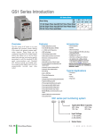
GS2 Series - Introduction
GS2 Series Drives
Motor Rating
Hp
kW
Single-Phase 115 Volt Class
Single/Three-Phase 230 Volt Class
Three-Phase 230 Volt Class
Three-Phase 460 Volt Class
Three-Phase 575 Volt Class
.25
0.2
.5
0.4
1
0.75
2
1.5
3
2.2
5
3.7
7.5
5.5
10
7.5
✔
✔
✔
✔
✔
✔
✔
✔
✔
✔
✔
✔
✔
✔
✔
✔
✔
✔
Features
Overview
The GS2 series of AC drives offers all of the
features of our GS1 drive plus dynamic
braking, PID and a removable keypad.
The drive can be configured using the builtin digital keypad or with the standard
RS-232/RS-485 serial communications
port. The standard keypad allows you to
configure the drive, set the speed, start and
stop the drive, command forward and
reverse direction of motor shaft, and
monitor specific parameters during operation. Each GS2 features one analog and
six programmable digital inputs, and one
analog and two programmable relay
outputs.
GS2 series
part numbering system
• Simple Volts/Hertz control
• Sinusoidal Pulse Width Modulation (PWM)
• 1-12 kHz carrier frequency
• IGBT technology
• Starting torque: 125% at 0.5 Hz/150% at 5 Hz
• 150% rated current for one minute
• Electronic overload protection
• Stall prevention
• Adjustable accel and decel ramps
• S-curve settings for acceleration and
deceleration
• Automatic torque compensation
• Automatic slip compensation
• Dynamic braking circuit
• DC braking
• Three skip frequencies
• Trip history
• Programmable jog speed
• Integral PID control
• Removable keypad with speed potentiometer
• Programmable analog input
• Programmable analog output
• Six programmable digital inputs
• Two programmable relay outputs
• RS-232/485 Modbus communications up to
38.4 Kbps.
• Optional Ethernet communications
• UL/cUL/CE* listed
* GS2-5xxx 575V drives NOT CE compliant
✔
✔
✔
✔
Accessories
• AC line reactors
• EMI filters
• RF filters
• Braking resistors
• Fuse kits and replacement fuses
• Ethernet interface
• Replacement keypads
• Keypad cables in 1, 3, and 5 meter lengths
• Four and eight-port serial communication
breakout boards
• KEPDirect I/O Server
• GSoft drive configuration software
Detailed descriptions and specifications for the
accessories are available in the “GS/DURAPULSE
Accessories” section.
Typical Applications
• Conveyors
• Fans
• Pumps
• Compressors
• HVAC
• Material handling
• Mixing
• Shop tools
GS2- 4 7P5
Applicable Motor Capacity
0P2: 0.25HP
1P0: 1.0HP
3P0: 3.0HP
7P5: 7.5HP
0P5: 0.5HP
2P0: 2.0HP
5P0: 5.0HP
010: 10HP
Input Voltage
1: 100-120VAC
2: 200-240VAC
4: 380-480VAC
5: 500-600VAC
Series Name
12–22
Drives/Motors/Motion
1 - 80 0 - 633 - 0405
GS2 Series Specifications
PLC
Overview
DL05/06
PLC
115V CLASS GS2 SERIES
Model
GS2-10P2
GS2-10P5
GS2-11P0
Price
<--->
<--->
<--->
HP
kW
Rated Output Capacity (kVA)
Rated Input Voltage
Rated Output Voltage
Rated Input Current (A)
Rated Output Current (A)
DC Braking
Protective Structure
Ambient Operating Temperature
Storage Temperature
Humidity
Vibration
Location
Watt Loss @ 100% I (W)
Weight: (lb)
Dimensions*** (HxWxD) mm( in)
1/4hp
1/2hp
1hp
0.2kW
0.4kW
0.75kW
0.6
1.0
1.6
Motor Rating
Line Reactor
Braking Resistor
EMI Filter
Fuse Kit
Single Phase**
Replacement Fuses Single Phase**
Spare Keypad, GS2 Series Drive
Keypad Cable, GS2 Series, 1 meter
Keypad Cable, GS2 Series, 3 meter
Keypad Cable, GS2 Series, 5 meter
Ethernet Communications module for GS2 Series
Drives (DIN rail mounted)
Four port RS-485 multi-drop termination board
Eight port RS-485 multi-drop termination board
Software
OPC Server
DL205
PLC
DL305
PLC
Single-phase : 100 to 120 VAC ±10% 50/60 Hz ±5%
DL405
PLC
Three-phase, two times proportion to input voltage
6
9
16
1.6
2.5
4.2
Frequency 60-0 Hz, 0-100% rated current, start time 0.0-5.0 seconds, Stop Time 0.0-25.0 seconds
Field I/O
Software
Protected chassis IP20
C-more
HMIs
-10°C to 50°C (14°F to 122°F) without derating
-20° to 60°C (-4° to 140°F) during short term transportation period
Other HMI
20 to 90% Humidity (no condensation)
9.8 m/s2 (1G) at less than 10 Hz; 5.9 m/s2 (0.6G) 10 to 60 Hz
AC Drives
Altitude 1,000m or less, Keep from corrosive gases liquids or dust
24
3.5
34
46
3.6
3.7
Motors
Steppers/
Servos
151.0 x 100.0 x 140.5. (5.94 x 3.94 x 5.53)
Accessories
Input side of drive (1 Phase)*
Output side of drive (3 Phase)*
DL105
PLC
GS-10P2-LR
GS-10P5-LR
GS-11P0-LR
GS-20P5-LR-3PH
GS-20P5-LR-3PH
GS-21P0-LR-3PH
GS-20P5-BR
GS-20P5-BR
GS-21P0-BR
Motor
Controls
Proximity
Sensors
Photo
Sensors
20DRT1W3S
GS-10P2-FKIT-1P
GS-10P5-FKIT-1P
GS-11P0-FKIT-1P
GS-10P2-FUSE-1P
GS-10P5-FUSE-1P
GS-11P0-FUSE-1P
GS2-KPD
Limit
Switches
Encoders
GS-CBL2-1L
Current
Sensors
GS-CBL2-3L
GS-CBL2-5L
Pushbuttons/
Lights
GS-EDRV
Process
GS-RS485-4
GS-RS485-8
Relays/
Timers
GSoft / KEPDirect
KEPDirect
Comm.
*Note: GS2-1xxx drives require 115V class input line reactors and 230V class output line reactors.
**Note: Single phase fuse kits and fuses are used only with GS2-1xxx drives.
TB’s &
Wiring
***Note: Height dimension does not include external ground terminal, which adds 10 to 15 mm. Refer to dimensional drawings for details.
Power
Circuit
Protection
Enclosures
Appendix
Part Index
w w w. a u to m at i o n d i re c t . c o m / d r i ves
Drives/Motors/Motion
12–23
GS2 Series Specifications
230V CLASS GS2 SERIES
Model
Price
Motor Rating
HP
kW
Rated Output Capacity (kVA)
GS2-20P5
GS2-21P0
GS2-22P0
GS2-23P0
GS2-25P0
<--->
<--->
<--->
<--->
<--->
<--->
1/2hp
1hp
2hp
3hp
5hp
7.5hp
0.4kW
0.75kW
1.5kW
2.2kW
3.7kW
5.5kW
1.0
1.9
2.7
3.8
6.5
9.5
Three-phase : 200/208/220/230/240 VAC
±10%, 50/60 Hz ±5%
Single/Three-phase : 200/208/220/230/240 VAC 앧10%, 50/6 0Hz 앧5%
Rated Input Voltage
Rated Output Voltage
Rated Input Current (A)
Rated Output Current (A)
DC Braking
Protective Structure
GS2-27P5
Three-phase : Corresponds to input voltage
6.3/2.9
2.5
11.5/6.3
15.7/8.8
27.0/12.5
19.6
28
5.0
7.0
10
17
25
Frequency 60-0 Hz, 0-100% rated current, start time 0.0-5.0 seconds, Stop Time 0.0-25.0 seconds
Protected chassis IP20
Ambient Operating Temperature
-10°C to 40°C
(14°F to 104°F)
without derating
-10°C to 50°C (14°F to 122°F) without derating
Storage Temperature
Humidity
Vibration
Location
Watt Loss @ 100% I (W)
Weight: (lb)
Dimensions* (HxWxD) mm (in)
-20° to 60°C (-4° to 140°F) during short term transportation period
20 to 90% Humidity (no condensation)
9.8 m/s (1G) at less than 10 Hz; 5.9 m/s2 (0.6G) 10 to 60 Hz
2
Altitude 1,000m or less, Keep from corrosive gases liquids or dust
34
57
77
111
185
255
3.5
3.6
3.7
8.5
8.5
8.5
151.0 x 100.0 x 140.5. (5.94 x 3.94 x 5.53)
220.0 x 125.0 x 189.5 (8.66 x 4.92 x 7.46)
Accessories
Line Reactor
Single-Phase GS-20P5-LR-1PH GS-21P0-LR-1PH GS-22P0-LR-1PH GS-23P0-LR-1PH
Three-Phase GS-20P5-LR-3PH GS-21P0-LR-3PH GS-22P0-LR-3PH GS-23P0-LR-3PH
Braking Resistor
EMI Filter (single phase input)
Fuse Kit
Replacement Fuses
GS-20P5-BR
GS-21P0-BR
GS-22P0-BR
20DRT1W3S
Single-Phase
Three-Phase
Single-Phase
Three-Phase
Spare Keypad, GS2 Series Drive
Keypad Cable, GS2 Series, 1 meter
Keypad Cable, GS2 Series, 3 meter
Keypad Cable, GS2 Series, 5 meter
Ethernet Communications module for GS2 Series
Drives (DIN rail mounted)
Four port RS-485 multi-drop terminaton board
Eight port RS-485 multi-drop terminaton board
Software
OPC Server
GS-23P0-BR
N/A
N/A
GS-25P0-LR
GS-27P5-LR
GS-25P0-BR
GS-27P5-BR
32DRT1W3C
40TDS4W4B
GS-20P5-FKIT-1P
GS-21P0-FKIT-1P
GS-22P0-FKIT-1P
GS-23P0-FKIT-1P
N/A
N/A
GS-20P5-FKIT-3P
GS-21P0-FKIT-3P
GS-22P0-FKIT-3P
GS-23P0-FKIT-3P
GS-25P0-FKIT-3P
GS-27P5-FKIT
GS-20P5-FUSE-1P GS-21P0-FUSE-1P GS-22P0-FUSE-1P GS-23P0-FUSE-1P
N/A
N/A
GS-20P5-FUSE-3P GS-21P0-FUSE-3P GS-22P0-FUSE-3P GS-23P0-FUSE-3P
GS-25P0-FUSE
GS-27P5-FUSE
GS2-KPD
GS-CBL2-1L
GS-CBL2-3L
GS-CBL2-5L
GS-EDRV
GS-RS485-4
GS-RS485-8
GSoft / KEPDirect
KEPDirect
*Note: Height dimension does not include external ground terminal, which adds 10 to 15 mm. Refer to dimensional drawings for details.
12–24
Drives/Motors/Motion
1 - 80 0 - 633 - 0405
GS2 Series Specifications
PLC
Overview
DL05/06
PLC
460V CLASS GS2 SERIES
Model
GS2-41P0
GS2-42P0
GS2-43P0
GS2-45P0
GS2-47P5
GS2-4010
Price
<--->
<--->
<--->
<--->
<--->
<--->
1hp
2hp
3hp
5hp
7.5hp
10hp
0.8kW
1.5kW
2.2kW
4kW
5.5kW
7.5kW
2.3
3.1
3.8
6.2
9.9
13.7
Motor Rating
HP
kW
Rated Output Capacity (kVA)
Rated Input Voltage
Rated Output Voltage
Rated Input Current (A)
Rated Output Current (A)
DC Braking
Protective Structure
Ambient Operating Temperature
Storage Temperature
Humidity
Vibration
Location
Watt Loss @ 100% I (W)
Weight: (lb)
Dimensions* (HxWxD) mm (in)
Three-phase: 380/400/415/440/460/480 VAC 앧10%, 50/60 Hz 앧5%
4.2
5.7
6.0
8.5
14
23
3.0
4.0
5.0
8.2
13
18
Frequency 60-0 Hz, 0-100% rated current, Start Time 0.0-5.0 seconds, Stop Time 0.0-25.0 seconds
DL305
PLC
Field I/O
Software
Protected chassis IP20
-10°C to 40°C(14°F to 104°F)
-20°C to 60°C (-4°F to 140°F) during short term transportation period
C-more
HMIs
Other HMI
20 to 90% Humidity (no condensation)
9.8 m/s2 (1G) at less than 10Hz, 5.9 m/s2 (0.6G)10 to 60 Hz
AC Drives
Altitude 1,000m or less, Keep from corrosive gases liquids or dust
73
86
102
170
240
255
3.5
3.6
3.7
8.5
8.5
8.5
151.0 x 100.0 x 140.5. (5.94 x 3.94 x 5.53)
220.0 x 125.0 x 189.5 (8.66 x 4.92 x 7.46)
Accessories
Line Reactor
Braking Resistor
EMI Filter
Fuse Kit
Replacement Fuses
Spare Keypad, GS2 Series Microdrive
Keypad Cable, GS2 Series, 1 meter
Keypad Cable, GS2 Series, 3 meter
Keypad Cable, GS2 Series, 5 meter
Ethernet Communications Module for GS Series
Drives (DIN rail mounted)
Four port RS-485 multi-drop terminaton board
Eight port RS-485 multi-drop terminaton board
Software
OPC Server
DL205
PLC
DL405
PLC
Corresponds to input voltage
-10°C to 50°C (14°F to122°F)
DL105
PLC
GS-41P0-LR
GS-42P0-LR
GS-43P0-LR
GS-45P0-LR
GS-47P5-LR
GS-4010-LR
GS-41P0-BR
GS-42P0-BR
GS-43P0-BR
GS-45P0-BR
GS-47P5-BR
GS-4010-BR
GS-41P0-FKIT
GS-42P0-FKIT
GS-43P0-FKIT
GS-45P0-FKIT
GS-47P5-FKIT
GS-4010-FKIT
GS-41P0-FUSE
GS-42P0-FUSE
GS-43P0-FUSE
GS-45P0-FUSE
GS-47P5-FUSE
GS-4010-FUSE
11TDT1W4S
17TDT1W44
Motors
Steppers/
Servos
Motor
Controls
Proximity
Sensors
26TDT1W4B4
Photo
Sensors
GS2-KPD
Limit
Switches
GS-CBL2-1L
Encoders
GS-CBL2-3L
Current
Sensors
GS-CBL2-5L
GS-EDRV
Pushbuttons/
Lights
GS-RS485-4
Process
GS-RS485-8
GSoft / KEPDirect
Relays/
Timers
KEPDirect
*Note: Height dimension does not include external ground terminal, which adds 10 to 15 mm. Refer to dimensional drawings for details.
Comm.
TB’s &
Wiring
Power
Circuit
Protection
Enclosures
Appendix
Part Index
w w w. a u to m at i o n d i re c t . c o m / d r i ves
Drives/Motors/Motion
12–25
GS2 Series Specifications
575V CLASS GS2 SERIES
Model
Price
Motor Rating
HP
kW
Rated Output Capacity (kVA)
Rated Input Voltage
Rated Output Voltage
Rated Input Current (A)
Rated Output Current (A)
DC Braking
Protective Structure
Ambient Operating Temperature
Storage Temperature
Humidity
Vibration
Location
Watt Loss @ 100% I (W)
Weight: (lb)
Dimensions* (HxWxD) mm (in)
GS2-51P0
GS2-52P0
GS2-53P0
GS2-55P0
GS2-57P5
GS2-5010
<--->
<--->
<--->
1hp
2hp
3hp
<--->
<--->
<--->
5hp
7.5hp
10hp
0.75kW
1.5kW
1.7
3.0
2.2kW
3.7kW
5.5kW
7.5kW
4.2
6.6
9.9
12.2
Three-phase: 500 to 600 VAC -15/+10%, 50/60 Hz 앧5%
Corresponds to input voltage
2.4
1.7
4.2
5.9
7.0
10.5
12.9
3.0
4.2
6.6
9.9
12.2
Frequency 60-0 Hz, 0-100% rated current, Start Time 0.0-5.0 seconds, Stop Time 0.0-25.0 seconds
Protected chassis IP20
-10°C to 50°C (14°F to122°F)
-10°C to 40°C(14°F to 104°F)
-20°C to 60°C (-4°F to 140°F) during short term transportation period
20 to 90% Humidity (no condensation)
9.8 m/s2 (1G) at less than 10Hz, 5.9 m/s2 (0.6G)10 to 60 Hz
Altitude 1,000m or less, Keep from corrosive gases liquids or dust
30
58
83
132
191
211
3.3
3.3
4.4
7.0
7.0
7.3
151.0 x 100.0 x 140.5. (5.94 x 3.94 x 5.53)
220.0 x 125.0 x 189.5 (8.66 x 4.92 x 7.46)
Accessories
Line Reactor
Braking Resistor
GS-51P0-LR
GS-52P0-LR
GS-42P0-BR
EMI Filter
Fuse Block (Edison 3-pole part #)
Replacement Fuses (Edison Fuse part #)
Spare Keypad, GS2 Series Microdrive
Keypad Cable, GS2 Series, 1 meter
Keypad Cable, GS2 Series, 3 meter
Keypad Cable, GS2 Series, 5 meter
Ethernet Communications Module for GS Series
Drives (DIN rail mounted)
Four port RS-485 multi-drop terminaton board
Eight port RS-485 multi-drop terminaton board
Software
OPC Server
GS-42P0-LR
GS-43P0-LR
GS-47P5-LR
GS-42P0-BR x (2)
in parallel
GS-4010-BR x (2)
in series
not available
BC6033PQ or CHCC3D or CHCC3DI
HCLR6
HCLR10
(10 fuses per pack) (10 fuses per pack)
HCLR15
(10 fuses per pack)
HCLR20
HCLR30
(10 fuses per pack) (10 fuses per pack)
GS2-KPD
GS-CBL2-1L
GS-CBL2-3L
GS-CBL2-5L
GS-EDRV
GS-RS485-4
GS-RS485-8
GSoft / KEPDirect
KEPDirect
*Note: Height dimension does not include external ground terminal, which adds 10 to 15 mm. Refer to dimensional drawings for details.
12–26
Drives/Motors/Motion
1 - 80 0 - 633 - 0405
GS2 Series — General Specifications
PLC
Overview
DL05/06
PLC
General Specifications
Control Characteristics
Control System
Output Frequency Resolution
Overload Capacity
Torque Characteristics
Braking Torque
DC Braking
Acceleration/Deceleration Time
DL105
PLC
Sinusoidal Pulse Width Modulation, carrier frequency 1kHz - 12kHz
0.1 Hz
DL205
PLC
150% of rated current for 1 minute
DL305
PLC
Includes auto-torque boost, auto-slip compensation, starting torque 125% @ 0.5Hz/150% @ 5.0Hz
20% without dynamic braking resistor, 125% with optional braking resistor
Operation frequency 60-0Hz, 0-100% rated current. Start time 0.0-5.0 seconds. Stop time 0.0-0 25.0 seconds
DL405
PLC
0.1 to 600 seconds (linear or non-linear acceleration/deceleration), second acceleration/deceleration available
Field I/O
Voltage/Frequency Pattern
V/F pattern adjustable. Settings available for Constant Torque - low and high starting torque,
Variable Torque - low and high starting torque, and user configured
Stall Prevention Level
Operation Specifications
20 to 200% or rated current
Software
C-more
HMIs
Inputs
Frequency
Setting
Keypad
Setting by <UP> or <DOWN> buttons or potentiometer
External Signal
Potentiometer - 3k to 5k액/2W, 0 to 10VDC (input impedance 10k액), 0 to 20mA / 4 to 20 mA (input impedance 250액),
Multi-speed inputs 1 to 3, Serial Communication RS232 and RS485 (Modbus RTU)
Operation
Setting
Keypad
Setting by <RUN>, <STOP> buttons
External Signal
Forward/Stop, Reverse/Stop (run/stop, fwd/rev), 3-wire control, Serial Communication RS232 and RS485 (Modbus RTU)
Input
Terminals
Digital
Analog
Outputs
Output
Terminals
Digital
2 user-programmable; Inverter Running, Inverter Fault, At Speed, Zero Speed, Above Desired Frequency, Below Desired
Frequency, At Maximum Speed, Over Torque Detected, Above Desired Current, Below Desired Current,
PID Deviation Alarm
Analog
1 user-programmable: 0 to 10VDC (max load 2mA), 8 bit resolution frequency, current, process variable PV
Operating Functions
Protective Functions
Operator
Interface
Options
Automatic voltage regulation, voltage/frequency characteristics selection, non-linear acceleration/deceleration, upper and
lower frequency limiters, 7-stage speed operation, adjustable carrier frequency (1 to 12 kHz), PID control, skip frequencies, analog gain & bias adjustment, jog, electronic thermal relay, automatic torque boost, trip history, software protection
Electronic Thermal, Overload Relay, Auto Restart after Fault, Momentary Power Loss, Reverse Operation Inhibit, Auto
Voltage Regulation, Over-Voltage Trip Prevention, Auto Adjustable Accel/Decel, Over-Torque Detection Mode,
Over-Torque Detection Level, Over-Torque Detection Time, Over-Current Stall Prevention during Acceleration,
Over-Current Stall Prevention during Operation
AC Drives
Motors
Steppers/
Servos
Motor
Controls
Proximity
Sensors
Photo
Sensors
Limit
Switches
Encoders
Operator Devices
Programming
8-key, 4-digit, 7-segment LED, 14 status LEDs, potentiometer
Status Display
Actual Operating Frequency, RPM, Scaled Frequency, Amps, % Load, Output Voltage, DC Bus Voltage,
Process Variable, Set-point Frequency
Key Functions
Enclosure Rating
RUN, STOP/RESET, FWD/REV, PROGRAM, DISPLAY, <UP>, <DOWN>, ENTER
Pushbuttons/
Lights
Protected chassis, IP20
Process
Ambient Temperature
Environment
6 user-programmable: FWD/STOP, REV/STOP, RUN/STOP, REV/FWD, Run momentary (N.O.), STOP momentary (N.C.),
External Fault (N.O./N.C.), External Reset, Multi-Speed Bit (1-3), Jog, External Base Block (N.O./N.C.),
Second Accel/Decel Time, Speed Hold, Increase Speed, Decrease Speed, Reset Speed to Zero, PID Disable (N.O.),
PID Disable (N.C.), Input Disable
1 user-configurable, 0 to 10VDC (input impedance 10k 액) or 0 to 20mA / 4 to 20mA (input impedance 250액 ), 10 bit
resolution Frequency setpoint or PID process variable PV
Other HMI
Storage Temperature
Ambient Humidity
Vibration
Installation Location
Parameter values for setup and review, fault codes
-10° to 50°C (14°F to 122°F)
-10° to 40°C (14°F to 104°F) For models 7.5Hp (5.5kW) and higher
Current
Sensors
Relays/
Timers
-20° to 60 °C (-4°F to 140°F) - during short-term transportation period
20 to 90% RH (non-condensing)
Comm.
9.8 m/s2(1G), less than 10Hz,. 5.9 m/s2 (0.6G) 10 to 60 Hz
Altitude 1000m or lower above sea level, keep from corrosive gas, liquid and dust
Noise filter, input AC reactor, output AC reactor, cable for remote operator, programming software (GSOFT),
Dynamic braking resistor, input fuses, ethernet interface (GS-EDRV), EMI filters
TB’s &
Wiring
Power
Circuit
Protection
Enclosures
Appendix
Part Index
w w w. a u to m at i o n d i re c t . c o m / d r i ves
Drives/Motors/Motion
12–27
GS2 Specifications — Installation
Understanding the installation requirements for
your GS2 drive will help to ensure that it operates within its environmental and electrical limits.
Note: Never use only this catalog for installation instructions
or operation of equipment; refer to the user manual, GS2-M.
Environmental Specifications
Fan
Protective Structure 1 IP20
Ambient Operating
Temperature 2
-10 to 50°C (14°F to 122°F) 10 to 40°C (14°F to 104°F) for
models 7.5HP and higher
Storage
Temperature 3
-20 to 60°C (-4°F to 140°F)
Humidity
To 90%
(no condensation)
Vibration 4
5.9 m/s2 (0.6g),
10 to 55 Hz
Location
Altitude 1,000 m or less,
indoors (no corrosive
gases or dust)
6in
[150mm]
minimum
2in
[50mm]
min
2in
[50mm]
minimum
1: Protective structure is based upon EN60529
2: The ambient temperature must be in the range of
-10° to 40° C. If the range will be up to 50° C, you
will need to set the carrier frequency to 2.1 kHz or
less and derate the output current to 80% or less.
See our Web site for derating curves.
6in
[150mm]
minimum
3: The storage temperature refers to the short-term
temperature during transport.
4: Conforms to the test method specified in JIS CO911
(1984)
Input
Power
Watt-loss Chart
GS2 Drive Model
At full load
GS2-10P2
GS2-10P5
GS2-11P0
GS2-20P5
GS2-21P0
GS2-22P0
GS2-23P0
GS2-25P0
GS2-27P5
GS2-41P0
GS2-42P0
GS2-43P0
GS2-45P0
GS2-47P5
GS2-4010
GS2-51P0
GS2-52P0
GS2-53P0
GS2-55P0
GS2-57P5
GS2-5010
24
e13–28
To
Motor
Warning: Maximum ambient temperatures
must not exceed 50°C (122°F), or
40°C (104°F) for models 7.5 hp
(5.5 kW) and higher!
34
46
34
57
77
111
Panel
Air Flow
Ground braid
copper lugs
185
255
73
86
Panel or single
point ground*
Star washers*
102
* FOR PAINTED SUB-PANELS, SCRAPE
170
THE PAINT FROM UNDERNEATH THE
240
STAR WASHERS BEFORE TIGHTENING
255
THEM.
30
58
83
Warning: AC drives generate a large amount of
heat which may damage the AC drive. Auxiliary
cooling methods are typically required in order
not to exceed maximum ambient temperatures.
132
191
211
Drives/Motors/Motion
1 - 80 0 - 633 - 0405
GS2 Specifications — Terminals
PLC
Overview
DL05/06
PLC
Main Circuit Wiring
Terminal Description
Input power
L1, L2, L3
AC drive output
T1, T2, T3
DB resistor input
B1, B2
DL105
PLC
DL205
PLC
Ground
DL305
PLC
DL405
PLC
Field I/O
Software
C-more
HMIs
Other HMI
AC Drives
Motors
Steppers/
Servos
Motor
Controls
Proximity
Sensors
Photo
Sensors
Limit
Switches
Control Circuit Terminals
Terminal Symbol
R1O
R1C
R1
R2O
R2C
R2
DI1
DI2
DI3
DI4
DI5
DI6
DCM
AI
+10V
AO
ACM
Encoders
Description
Relay output 1 normally open
Current
Sensors
Relay output 1 normally closed
Relay output 1 common
Relay output 2 normally open
Pushbuttons/
Lights
Relay output 2 normally closed
Process
Relay output 2 common
Digital input 1
Digital input 2
Relays/
Timers
Digital input 3
Comm.
Digital input 4
Digital input 5
TB’s &
Wiring
Digital input 6
Digital common
Power
Analog input
Internal power supply (DC 10V) @ 10 mA
Circuit
Protection
Analog output
Analog common
Enclosures
Note: Use twisted-shielded, twisted-pair or shielded-lead wires for the control signal wiring. It is recommended to run all signal wiring in a separate steel conduit.
The shield wire should only be connected at the drive. Do not connect shield wire on both ends.
Appendix
Part Index
w w w. a u to m at i o n d i re c t . c o m / d r i ves
Drives/Motors/Motion
12–29
GS2 Specifications — Basic Wiring Diagram
Note: Users MUST connect wiring according to the circuit diagram shown below. (Refer to user manual GS2-M for additional specific wiring information.)
Note: Refer to the following pages for explanations and information regarding line reactors, braking resistors, EMI and RF filters, and fuses:
12–50, 12–56, 12–61, 12–67, 12–68.
Power Source*
100-120V ±10%
200-240V ±10%
380-480V ±10%
500-600V -15%;+10%
(50,60Hz ±5%)
AC Motor
L1
GS2-xxxx
L2
T1
IM
T2
T3
L3
* Use terminals L1, L2 for 115V 1-phase
models; use any two of L1, L2, L3 for
230V 1-phase models.
Grounding resistance
less than 0.1⏲
B1
Braking resistor
(optional)
B2
R1
R1C
Multi-function output contacts
120VAC/24VDC @5A
230VAC @2.5A
R1O
Inverter Running
DI1
Forward/Stop
DI2
Reverse/Stop
R2
DI3
External Fault
(N.O.)
Multi-function output contacts
120VAC/24VDC @5A
230VAC @2.5A
R2C
R2O
DI4
Inverter Fault
Multi-Speed 1
DI5
Analog
AO
output
0 to +10 VDC
2mA max
Multi-Speed 2
DI6
Multi-Speed 3
Potentiometer (3-5 k⏲) (may be
required for some
meters)
+
Voltmeter
-
ACM
Output Frequency
DCM
Analog voltage
0-10 VDC
Potentiometer
3-5 k⏲
Analog current
0-20 mA
4-20 mA
+10V
(10mA max)
AI
RJ-12
(6P4C)
6
RJ-12 Serial Comm Port
Interface (see note below)
1
ACM
RS-485
2: GND
3: SG4: SG+
5: +5V
RS-232
2: GND
3: RXD
4: TXD
5: +5V
Factory default setting
Factory default source of frequency command is via the keypad potentiometer
Main circuit (power) terminals
Control circuit terminal
Shielded leads
WARNING: Do not plug a modem or telephone into the GS2 RJ-12 Serial Comm Port, or permanent damage may result.
Terminals 2 and 5 should not be used as a power source for your communication connection.
12–30
Drives/Motors/Motion
1 - 80 0 - 633 - 0405
GS2 Specifications — Dimensions
PLC
Overview
DL05/06
PLC
GS2-10P2, GS2-10P5, GS2-11P0; GS2-20P5, GS2-21P0, GS2-22P0;
GS2-41P0, GS2-42P0, GS2-43P0; GS2-51P0, GS2-52P0, GS2-53P0
DL105
PLC
DL205
PLC
DL305
PLC
DL405
PLC
Field I/O
Software
C-more
HMIs
Other HMI
AC Drives
Motors
Steppers/
Servos
Motor
Controls
Proximity
Sensors
GS2-23P0, GS2-25P0, GS2-27P5;
GS2-45P0, GS2-47P5, GS2-4010; GS2-55P0, GS2-57P5, GS2-5010
Photo
Sensors
Limit
Switches
Encoders
Current
Sensors
Pushbuttons/
Lights
Process
Relays/
Timers
Comm.
TB’s &
Wiring
Power
Circuit
Protection
Enclosures
Appendix
Part Index
w w w. a u to m at i o n d i re c t . c o m / d r i ves
Drives/Motors/Motion
12–31