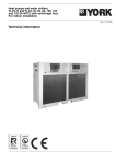
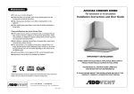
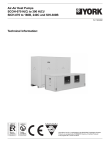
1
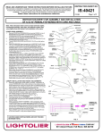
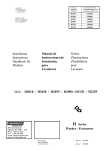
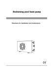
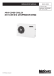
SWIMMING POOL HEATER
PLASTIC SHELL
Directions for installation and maintenance
Model : KS120 / KS150 / KS200 / KS250
RoHS
-Please read this operating manual before using the Heat Pump -
Summary
1. Introduction
2. Caution
………………….…………………………….…………….p3
…………………………………………………….………………..p3
3. Delivery control …………………………………………........................p4
4. Technical description …………………………………………………….. p4
Technical characteristics
General diagram of the refrigerating circuit
Exploded Views
Safety and control systems
Electric diagram
5. Installation…………………………………………………………............ p10
Rules of installation
Hydraulic connections
Electric connections
Description of the order and display panel
Procedure of use
Adjustment of operation timetable(timer)
Setting
6. Water flow and refrigerating circuit pressure........................p18
7. Defrosting ……………………………………………………………………p18
8. Environment problem …………………………………………............p19
9. Regular operations of maintenance …………………………….... p19
10. Error messages and what to do…………………………………… p20
11. Problems / solutions ……………………………………................. p21
12. Further recommendations ……………………………………........ p22
-2-
1- Introduction
Thank you for choosing our heat pump.
This installation and maintenance notice contains the necessary
information to its installation (delivery control, the installation, the
connections) and to its repair. It is a complementary document to
the user’s manual which describes its instructions for use.
We invite you to read it first.
2- Caution
This document is an integral part of the product and it must stays in
the technical room.
This Heat pump is exclusively for heating swimming pools.
Any other use not in conformity and random will be considered as
dangerous and unsuitable.
The assembly, the electric connection and the start up must be
carried out by specialized and professional person.
It is essential to maintain the temperature in the swimming pool
lower than the recommended value by the swimming pool’s
manufacturer.
In a concern to a constant improvement, our products can be
modified without notice; the present pictures in this note or the
characteristics which are described are not contractual.
CAUTION
1 . WHEN NO NEED TO USE THE HEAT PUMP IN WINTER,
PLEASE DRAIN THE SYSTEM’S WATER OUT COMPLETELY,
TO PREVENT THE DAMAGE TO HEAT EXCHANGER.
2 . TO ENSURE THE HEAT PUMP’S EFFICIENCY AND SAFETY,
PLEASE PERIODICITY CLEAN THE WATER CIRCUIT INSIDE
HEAT PUMP.
-3-
3- Delivery’s control
At the delivery time, check the condition of packing; in case of
damages, have reservation about them to the carrier, before 48
hours and by registered letter with acknowledged receipt.
Before any manipulation, check the complete state of the machine.
4- Technical description
Model
Air discharge
Shell material
Heating capacity
Rated power in
COP
Noise
Power supply
Rated current in
Max current in
Temperature
Compressor
Refrigerant R410a
Manometer
Fan quantity
Min water fiow
Water connect
Heat exchanger
Flow switch
Pressure protect
Display
Auto-defrost
Microcomputer control
Wire control
Packing method
Unit dimension
Packing dimension
Net/shipping weight
Loading quantity(40HQ)
Model for heating only
KW
KW
dB(A)
V/Ph/Hz
A
A
℃
Type
g
L/min
Inch
LXWXH(mm)
LXWXH(mm)
Kg
Sets
KS120
Vertical
Plastic
12.0
2.76
4.35
49
230/1/50
13.2
15
5-40
KS150
Vertical
Plastic
14.5
3.18
4.5
50
230/1/50
14.3
16.1
5-40
KS200
Vertical
Plastic
19.5
4.52
4.3
55
400/3/50
8.0
9.46
5-40
KS250
Vertical
Plastic
24.3
5.78
4.2
55
400/3/50
8.8
11.1
5-40
Rotary
Scorll
Scroll
Scroll
1850
2450
2800
3000
Yes
Yes
Yes
Yes
1
1
1
1
90
100
130
130
2
2
2
2
Titanium PVC Titanium PVC Titanium PVC Titanium PVC
Yes
Yes
Yes
Yes
HP and LP
HP and LP
HP and LP
HP and LP
LED
LED
LED
LED
Yes
Yes
Yes
Yes
Yes
Yes
Yes
Yes
Option
Option
Option
Option
Wood
Wood
Wood
Wood
670/610/958 670/610/958 793/725/980 793/725/980
740/670/1090 740/670/1090 840/755/1105 840/755/1105
75/97
82/104
100/130
109/130
96
96
84
84
KS120N
KS150N
KS200N
KS250N
Heating capacity is based on inlet water temperature 25℃,Ambient air temperature 24℃(DB)/19℃(WB)
-4-
General diagram of the refrigerating circuit
The heat pump is reversible allowing the swimming-pool’s heating or
cooling:
Swimming-pool water’s heating mode:
The cold and liquid refrigerant fluid absorbs the heat contained in the air through
the evaporator (gilled radiator), in which it is vaporizing; it is then put up in
pressure and in temperature by the compressor which sends it in the condenser
(exchanger) where it loses its heat (in giving it to the water of swimming pool) and
comes back in liquid state; it loses its pressure and still cools in the expansion
capillaries before turning back to the evaporator for a new cycle.
Hot air
3-way
valve
Evaporator
(gilled radiator)
Cold air
Pressure and Gas
intake
Expansion
capillar y
4-way valve
Hot water
Cold water
Compressor
Titanium pipe
heat exchanger
-5-
Swimming-pool water’s cooling mode: *
The 4 way valve reverses the circulation of the refrigerant fluid; the fluid vaporizes
in the exchanger (evaporator) in getting the heat of the water, goes through in the
compressor which reheats it and through in the gilled radiator (which becomes
condenser) where it comes back to liquid state.
Cold air
3-way
valve
Evaporator
(gilled radiator)
Hot air
Pressure and Gas
intake
Expansion
capillar y
4-way valve
Cold water
Hot water
Compressor
Titanium pipe
heat exchanger
-6-
Exploded Views
17
18
10
14
15
19
20
12
13
11
9
16
22
8
21
28
6
7
27
1
26
25
24
5
2
3
4
14
Compressor
28
Flow detector
13
Left Pillar
27
Circuit Board
12
Manometer
26
Transformer
11
Four Way Valve /Copper Pipe
25
Motor Capacitor
10
Fan motor
24
Public Terminal
9
Filling gas valve
23
Terminal
8
Filter
22
Compressor Capacitor
7
High Pressure switche
21
Electrical Box
6
Low Pressure switche
20
Right Front Panel
5
Capillary
19
Defrost Sensor
4
Chassis
18
Condenser
3
Titanium and PVC Heat Exchanger
17
Top cover
2
Power Cord
16
Liquid reservoir
1
Left Front Panel
15
Right Pillar
-7-
23
Safety and control systems
The heat pump is fitted out:
With 2 control systems :
A temperature sensor of the evaporator, starting the defrosting operation.
A temperature sensor placed on the exchanger, ensuring the cut of the heat
pump when the temperature of the water reaches the required temperature.
The normal cycle restarts when the temperature in the exchanger goes down
to a temperature lower of 2°C than this required.
With 4 safety systems:
A water flow detector placed at the entry of the exchanger
A high pressure gas circuit breaker, a low pressure gas circuit breaker
An outlet compressor temperature sensor
Integrated to the card, a magnetic ammeter/circuit breaker on the compressor.
If a defect occurs on one of these systems (defective system, off-line or abnormal
measured value) a message of defect appears on the display screen; see the
paragraph “Error codes and what to do” of this note.
Caution: the removal or the shunt of one of the control or safety systems involves
the cancellation of the guarantee.
Electric diagram
KS120
S
R
Y/G
BLACK
Y/G
C1
WHITE
FM
BLUE
RED
C1
CM C
RED
WIRING DIAGRAM
BLUE
T1
LDB-1
L
N
WHITE
4
3
BLACK
BLACK
4
3
PCB
T1
BROWN
RED
CN4
CN3
FLOW
SWITCH
LOW PRESSURE HIGH PRESSURE
SWITCH
SWITCH
3
LED
/
A1
CONTACTOR
COMPRESSOR
TEMPERATURE
AMBIENT
TEMPERATURE
WATER
TEMPERATURE
COPPER
SENSOR
L
N
BLACK
WHITE
Y/G
COMPRESSOR
CAPACITOR
FAN MOTOR
CAPACITOR
-8-
230V 50Hz
CN2
BLACK
OUT3 OUT4 OUT5
4WV1 4WV2 OFAN
BLUE
TRANSFORMER
CN1
L1
A2
BLUE
XT1
BLUE
BLUE
Electric diagram
KS150
WIRING DIAGRAM
BLACK
R
Y/G
BLUE
RED
S
CM C
Y/G
C1
WHITE
FM
RED
BLUE
C2
4
3
T1
LDB-1
L
N
WHITE
BLACK
4
3
PCB
BROWN
RED
COMPRESSOR
TEMPERATURE
AMBIENT
TEMPERATURE
WATER
TEMPERATURE
COPPER
SENSOR
CN4
CN3
C3
BLACK
T1
A2
FLOW
SWITCH
LOW PRESSURE HIGH PRESSURE
SWITCH
SWITCH
L1
3
LED
/
A1
230V 50Hz
R
CN2
BLACK
2
1
OUT3 OUT4 OUT5
4WV1 4WV2 OFAN
BLUE
TRANSFORMER
CN1
RELAY
5
BLUE
XT1
BLUE
BLUE
L
N
BLACK
CONTACTOR
WHITE
Y/G
C OM P R E SSO R
C A P A CI TO R
FA N M OT O R
CA P AC I T O R
COM PRE SSO R STA RT
CAP ACI TOR (60 uf )
C3
KS200 / KS250
WIRING DIAGRAM
CONTACTOR
BLACK
BLACK
IN
BLACK
R
PCB2 S
OUT
Y/G
BROWN
XT1
RED
T
380V 3N~50Hz
CM
L1
L2
L3
N
WHITE
BLACK
BROWN
RED
A2
T1
T2
T3
A1
L1
L2
L3
BLACK
W
WHITE
U
RED
V
BLACK
WHITE
LED
/
3
FLOW
SWITCH
LOW PRESSURE
SWITCH
HIGH PRESSURE
SWITCH
N
3
4
4
PCB
COMPRESSOR
TEMPERATURE
AMBIENT
TEMPERATURE
WATER
TEMPERATURE
COPPER
SENSOR
CN4
FM
BLUE
RED
RED
CN3
3
C1
Y/G
LDB-1
T1
BROWN
L
TRANSFORMER
Y/G
WHITE
CN1
CN2
OFAN
OUT5
4WV2 OUT4 4WV1 OUT3
YV1
BLUE
BLUE
YV2
BLUE
BLUE
FAN MOTOR
CAPACITOR
YV2
-9-
FOUR WA Y
VALVE 2
5- Installation
Rules of installation:
Electric and hydraulic connections must be carried out according to
standards in effect (NF C 15 100, CE I 364).
The machine must be installed outside.
The machine must be posed on its antivibratory studs, set and lying flat and on a
massive base (concrete slab); this base must have a sufficient height to prevent
any entry of water by the bottom of the machine. Height must be adjusted to fit
the connector collecting the condensates.
The obstacles such as wall and vegetation must be separated from the machine
as indicated on the diagram below.
Exhausting
side
0,3 m mini
0,5 m mini
2,5 m mini
Blowing
side
0,5 m mini
Do not to install the Heat pump in a confined place (the fan would recycle its air
and the Heat pump would be down performance).
The fan should not blow towards the windows or crossing point.
Safety distance between the swimming pool and the foot bath: the fitter must
imperatively refer to the standard C15-100 section 702; the machine should not be
installed in volume 1 surrounding the swimming pool but at least in volume 2 so at
a distance of 3 m minimum of the swimming pool and foot bath.
Other precautions of installation:
- Do not to install the machine near a way with circulation of car in order to avoid
mud projections.
- Avoid directing blowing against dominant winds.
- If the machine is intended to be used in winter, put it in a place protected from
the falls of snow.
- The machine must be able to be supervised in order that children do not play
around
- 10 -
- 11 -
To respect imperatively
Connection is carried out with a by-pass located on
the circuit of filtration, upstream appliances of the
chemical treatment of water.
Connect intake/outlet water PVC pipes DN50 to the
openings of the machine in following the inlet /
outlet indications (grease the worms before
screwing)
Hydraulic connections:
Electric connections:
CAUTION: before connecting the machine, make sure that the feeder is
disconnected to the electrical network.
The electric installation must be carried out by an experienced electrician and the
supply must come from a severing equipment and differential protection; the
whole must be carried out according to standards' in force in the country where
the material is installed.
Characteristics of the electric supply:
- For KS120 and KS150: 230V +/- 10%, single-phase current, 50Hz,
- For KS200 and KS250: 400V +/- 10%, triple-phase current, 50Hz,
- Mode of neutral TT and TN.S; the circuit of heat pump must be connected to an
earth circuit.
Characteristic minimum of the protection:
- Protection must be of 16A, by circuit breaker or fuse; it must protect the Heat
pump exclusively; the circuit breaker must be specified with curve D, the fuse
must be specified Am.
- Differential protection : 30mA (the length of cable between the connector block
of the heat pump and the protection of should not exceed 12m).
Control :
The heat pump is fitted out with a flow detector which function is to apply
the voltage to the electronic card when the water flow is sufficient.
We recommend when it is possible to control the heat pump to the filtration pump
(by contacting relay non supplied to insert in the feeding circuit of the heat pump).
Removed control panel:
An extension cord allows the removal of the panel in inserting it in a
standard electric box into the technical local; the option is supplied with a cover
allowing to seal the aperture let by the removal of the control panel.
- 12 -
Description of the order and display panel :
21 . 28
Buttons
Function
ON / OFF
Heating mode & Cooling
mode selection / Defrost Setting
-
Light of heating mode running
/ Flashing when heat pump defrosting
Light of cooling mode running (invalid in the heating only system)
Adjustment of the temperature desired;
Adjustment of the start and stop hour;
Adjustment of the temperature desired;
Adjustment of the start and stop hour;
Force Defrost / Temperature display
To adjust the current hour and function timetable ( set a starting hour )
To adjust the current hour and function timetable ( set a stopping hour )
To set the hour
- 13 -
Procedure of use
External appliance
or button of heat
pump
Put the heat pump
under tension
Display
Engage the circuit
breaker of the heat
pump
Heat pump answer
13 :21
Indicate the current hour
Put in circulation the
Heat pump
into the pipes
Start
Go from heating mode
to cooling mode or
inversely from cooling
to heating
Set the wished
temperature into the
Heat Pump
Engage the circuit
breaker of pump of
filtration
21
Indicate the current hour
Start between 1 second
and 4 minutes in the last
active mode (heating or
cooling)
Press the button
Press the button
21
28
Up and Down
28
Stop for 4 minutes,
reverse of cycle and
restart in a new mode
The heat pump heats or
cools until the required
temperature
adjustable from
5°C to 35°C (Cooling mode)*
10°C to 35°C (Heating mode)
Stop
Switch off
Press the button
13 :21
Use the circuit breaker
of pump of filtration
Immediately stop and
wait
Completely stop
- 14 -
Adjustment of operation timetable(timer):
Setting the time
If the pump is running , press
Press on the
to stop it.
for 5 seconds. The hour setting
21 :13
The left-digit flash
mode is activated, the hours light.
15:13
Set the hour using the
15:13
Press
The right-digit flash
Set the minutes using the
15:30
press
15:30
once again (or wait around 10
seconds, the display will leave the setting mode by itself)
Setting times of hours
Press on the
twice
(TIMER)
21 :13
The left-digits (hour) flash
15:13
Set the hour using the
Press
15:13
to go to minutes setting
The right-digits (hour) flash
Set the minutes using the
15:30
Press
15:30
to confirm the setting
- 15 -
Settings
Manual defrosting:
The heat pump is set for defrosting automatically.
Under special conditions, it is possible to force defrosting by pressing the buttton
. The default force defrost time is 8 minutes. This defrosting could be
stopped by pressing the button OFF.
Temperature display:
Press on
for 4 seconds to enter the Temperature display.
Press on
again to enter the next item temperature display.
current
temperature
Item NO.
6 28
Item NO.
Meanings
6
Temperature of the water
7
Temperature of the ambient
8
Defrost sensor temperature
9
Compressor exhaust temperature
Defrosting setting:
Press on
for 3 seconds to enter the Defrosting setting.
Set each parameter using
Press on
and
according the table below.
to enter the next Item ;
After setting the value, the defrosting setting will exit automatically after
several seconds. And the system will memorize the last value of each setting.
- 16 -
Setting
Value
Item NO.
1 -7
Parameter
Meanings
Range
0
Flow switch detection
0/1
1
Defrost starts temperature
NO.
Default
Value
Remark
0
adjustable
-30~0℃
-7 ℃
adjustable
2
Defrost stops temperature
0~30 ℃
10℃
adjustable
3
Interval of defrost
30~90min
45min
adjustable
4
Time of defrost
1~20min
8min
adjustable
Detection of flow switch (0 / 1):
A) When choosing 0, the detection does not work in 10 minutes after compressor
running; 10 minutes later start to detect, if it is display error code Eb, machine will
be stop then.
B) When choosing 1, it starts to detect as soon as compressor start, if it is display
error code Eb, machine will be stop then.
Reset Button:
when press the button
for 4 seconds, and the following points will
return to initial state (Windows default):
0. Flow switch detection:0
1. Defrost starts temperature: -7℃
2. Defrost stops temperature: 10℃
3. Interval of defrost : 45 minutes
4. Time of defrost : 8 minutes
- 17 -
6- Water Flow and refrigerating circuit pressure
After putting into service, do the settings of pressure of the refrigerant
circuit for having an optimal operating of the heat pump, following:
Stage 1:
Access to the seal of the filling gas valve
in removing the rubber cover ; before starting
the Heat Pump, connect the manometer, the
needle must shows before starting and to an
ambient temperature around 20°C, a pressure
from 14 to 16kg/cm².
Stage 2:
Close completely the by pass valve and open largely inlet and outlet valves
of the Heat Pump; in these conditions the totality of the water flow goes by
the Heat Pump.
Put into service the Heat Pump in heating mode, wait for the indicated
pressure being stabilized; the correct setting of the pressure is from 28 to
30 kg/cm²;
In most of cases (pump of filtration given a flow until 20m3/h) you do not
have to open the by pass valve.
If the stabilized pressure is under 28kg/cm², the progressive opening of the
by pass valve will allow rising this pressure.
The adjustment of the by pass valve done, you have in principle no reason
to modify it during the season. See the paragraph “Environment problem”
too.
7- Defrosting
The defrosting is necessary only in heating mode.
Sequences of the defrosting:
1- Start
The defrosting is engaged if the following conditions are at the same time
fulfiled:
- the compressor and the fan motor run without stopping;
- the defrosting sensor temperature lower than 3°C, and the duration of time
more than 45 minutes;
- the defrosting sensor temperature goes down to -7°C(factory setting).
2- The compressor and the fan stop
3- After 10 seconds, the 4 way valve shifts
4- Five seconds after its stop, the compressor starts alone and the
accumulated freeze on the gills becomes melting, what is generally with a steam
cloud.
5- Stop:
The defrosting stops if one of the following conditions is fulfiled:
- the defrosting operates 20 seconds and the detected temperature by the
defrost sensor goes up to 10°C(factory setting).
- the defrosting mode had run totally 8 minutes
6- The compressor stops
7- After 10 seconds the 4 way valve shifts
8- Five seconds after its stop the compressor and the fan start for restarting
in heating mode.
- 18 -
8 – Environment problem
Under certain external conditions the heat exchanges between the refrigerant and
the water on one hand and between the fluid and the air on the other hand are
insufficient; the consequence is that the refrigerating circuit runs up in pressure
and the compressor consumes more electricity.
The temperature sensors compressor outlet and the magnetic circuit
breaker on the compressor power supply protect the compressor from these
extreme conditions; the error messages E 05 or E 06 occur.
The condition causing this situation is as follows:
In heating mode:
- insufficient water flow: close the by-pass valve for increasing the
heat exchange ( refrigerant Æ water )
In cooling mode:
- too big water flow: open the by pass valve for decreasing the water
flow and make the heat exchange ( water Æ refrigerant ) more electricity.
- insufficient air flow: be sure that the gills of the radiator are not blocked.
Note: these error codes are likely to occur if temperature of swimming pool water
is high and the ambient air is hot.
9 - Regular operations of maintenance
Washing the sand filter of your filtration installation :
Stop the Heat pump
Wintering :
Stop and put the heat pump out of tension
Stop and put the filtration pump out of tension
Entirely unscrew the 2 connections on the Heat pump and have each pipe slip to
make leave the openings coming out from the heat pump ; the Heat pump gets empty,
wait for the complete emptying.
(THE EXCHANGER MIGHT BURST IF IT HAS NOT EMPTIED COMPLETEY)
Put back each pipe to its place and screw again the connections to entirely close
again (to avoid little animal’s entry)
Remark : supplement the draining of your filtration installation or call your fitter
(all your installation must be protected against the freezing)
Maintenance :
Make sure that nothing comes to block the gilds radiator, if it’s necessary clean
it with a soft brush (no water jet under pressure);
Make sure that the gilds are right, rectilinear, if it’s necessary rectify them with
a fine comb;
Make sure that the flue of the condensates is not blocked.
- 19 -
10 – Error codes and what to do:
This table explains the error codes caused by a defective
regulating component or by a security operation.
E1
Screen and state
of the heat water
pump
E1
The heat pump
continues running
E2
The compressor stops
and after the fan stops
too
E3
The heat pump
continues running
Component
Possible
Intervention
Water temp sensor
Sensor disconnected,
non supplied or
defective
Check the connections, the wires, change
it or replace the electronic card
Ambient air
temperature sensor
Sensor disconnected,
non supplied or
defective
Check the connections, the wires, change
it or replace the electronic card
Oultlet compressor
temperature sensor
E4
Compressor and fan
stop
Defrosting system
E5
Magnetic ammeter
E6
Compressor and fan
stop
Oultlet compressor
temperature sensor
E7
Compressor and fan
stop
Magnetic circuit
breaker
Eb
Flow switch
Sensor disconnected,
non supplied or
defective
The defrosting is
incomplete and the
automatism decides to
stop the heat pump
The compressor stops 3
times in 24h because of
intensity excess in the
compressor
Oultlet compressor
temperature detected
up to 105°C more than
3 times in 24h
Electric current leak
from the compressor,
from the fan or from an
electrovalve; electric
safety system of the heat
pump
Flow switch
disconnected, non
supplied or defective
Second
reason if the
intervention
is without
effect
Check the connections, the wires, change
it or replace the electronic card
Increase lightly the water flow going into
the heat pump; the effect is to increase the
temperature of the refrigerant in the
evaporator.
Environment problem
Environment problem
Switch off the current and call an
electrician for repairing or replacing the
defective component
Check the connections, the wires, change
it or replace the electronic card
Compressor
piston clamped,
call a
refrigerating
engineer
The compressor hums
without starting and
the electric supply
breaks
Starting condenser
of the compressor
The condenser is
defective
Replace the
condenser
E9
High pressure
pressostat
Pressostat is
disconnected, or
defective
Call a refrigerating engineer who will do
the necessary controls of the circuit
pressure
EA
Low pressure
pressostat
Pressostat is
disconnected, or
defective
Call a refrigerating engineer who will do
the necessary controls of the circuit
pressure
- 20 -
11 - Problems / solutions :
The difficulties met the most often can be solved by reading the table
below.
If nothing corresponds to the list, or if the solutions applied do not solve
the problem, refer to DIRECTIONS FOR INSTALLATION AND
MAINTENANCE or contact your retailer.
Difficulty
The heat pump does
not start
Observation
Probable cause
Explanation / Solution
Extinct screen
No power
Check that the circuit breaker
of the table is engaged in the
technical room
Extinct screen and heat
pump supplied in power
The power supply is
defective
Call your retailer
Extinct screen, filtration is
working
Water is running
below the heat pump
The water comes from the
bottom of the heat pump
The temperature of
the swimming pool is
increasing very slowly
The heat pump works
White frost or ice
appears outside on the
gilds of the evaporator
The layer of the white frost
is thin
The layer of the white frost
is thick (the blades of the
ventilator may rub on the
ice much thicker inside)
The heat pump emits
noises of vibration or
sheet
The vibrations can be
located or the heat pump is
not stable
The in and out pipes of the Check on the heat pump that
heat pump are reversed or the in and out pipes are not
reversed. Check the filtration
the flow switch is not
pump works or is not defused
sufficient
It’s natural : these condensates
Drain of the condensates
are caused by condensation of
not installed or stopped :
the humid air on the gilds of
black, plastic conduit
the evaporator
prolonged with a flexible
pipe of evacuation
The rising in temperature is more or less rapid according to
the volume of the swimming pool and to the climatic
conditions. An isothermic cover will improve the
performances in heating
The outside temperature
See the paragrah 5 of this
is low and the air is humid manuel
Outside temperature very
low and air very humid
The automatic de-icing is not
sufficient ; stop the heat pump
for the operations of wintering
It’s not horizontal or not
well fixed ; the pipes may
have moved into the pump
during the transport or
the installation
Call your retailer
- 21 -
12 - Further recommendations:
Linked to the Directive of the under Pressure Equipment (PED-97/23/CE)
1.
•
•
•
•
•
•
•
•
•
•
10
•
•
•
•
•
•
•
•
Installation and Maintenance
Before any intervention on the machine, installation, startup, use, maintenance, the staff will have to know all of the
instructions and recommendations shown into the notice of the apparatus, and the technical file of the project.
The staff taking delivery of the apparatus, will have to control visually that the apparatus has not had any damage during
the transport : refrigerating circuit, electric box, frame and carossery.
It’s prohibited to use the apparatus near :
a. a heat source
b. combustible materials
c. a return air grille of air of an adjacent building
For some apparatuses, you have to use the protective grille if it’s located in a place of which the access is not ruled.
The apparatus must be installed, started, maintained, repaired by a qualified staff, with respect to the requirements of the
directives, laws, rules of the country and with respect to the rules of the profession.
During the installation, repairing, maintenance, you are not allowed to use pipes as a footboard. The pipe could break
under the weight, and the refrigerant could entail serious burns
During the maintenance of the apparatus, you’ll control the composition and the state of the coolant fluid, and that there is
no trace of refrigerant.
During the annual control of the sealing of the apparatus, with respect to the rules in force, check that the high and low
pressure controllers are connected directly to the refrigerating circuit and that they cut the electric circuit in case of release.
During the maintenance, make sure that there are no traces of corrosion or of oils around the refrigerating components.
Before intervening on the refrigerating circuit, you have to stop the apparatus and to wait for a few minutes, before posing
temperature or pressure gauges. Some equipment as the compressor and the pipes can reach temperatures superior to
100°C and high pressures can entail serious burns.
Repairing
Any intervention on the refrigerating circuit will have to be done with respect to the code of practice and safety in force
into the profession : recovery of the refrigerant, brazing under nitrogen, etc.
Any brazing will have to be done by qualified brasors.
For the apparatuses filled of R410a, refer to the specific instructionsinto the use notice.
The pipes will have to replaced only by copper tube conform to the NF EN 12735-1.
Detection of leaks, case of test under pressure :
Never use oxygenate or dry air, due to fire or explosion hazard
Use nitrogenize dehydrated or a mixture of nitrogenize and refrigerant as shown on the descriptive badge
The pressure of the test side low and high pressure must not exceed 20 bars and 15 bars when the
apparatus is equipped with a manometer.
As regards the pipes of the high pressure circuit, made with copper tube of a diameter equal or superior to 1’’ 5/8, you’ll
have to request a certificate §2.1 according to the norm NF EN 1020004 to the supplier and keep the certificate into the
technical file of the installation.
Any replacement of a piece by another one, any modification of the refrigerating circuit, any replacement of the
refrigerant by a fluid different from the one shown on the descriptive badge, any use of the apparatus beyond the
applications shown into the documentation, would entail the cancellation of the marking CE conform to the PED, and
would be placed under the responsibility of the person having done those modifications.
The technical information concerning the requirements of safety of the differents directives applied, are shown on the
descriptive badge. All of these pieces of information must be registered on the installation notice of the apparatus, which
must be shown on the technical file of the installation :
- Model - code – serial number
- TS maxi and mini
- PS
- Year of manufacturing
- Marking CE
- Address of the manufacturer
- Refrigerant and weight
- Electrical parameters
- Thermodynamic and acoustic performances
DECLARATION OF CONFORMITY
Heat pumps of swimming pools
KS120N/R KS150N/R KS200N/R KS250N/R
are conform to the provisions
of the directive ELECTROMAGNETIC
COMPATIBILITY 89/336/CEE
of the directive LOW PRESSURE
73/23/CEE
- 22 -