1
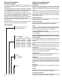
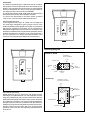
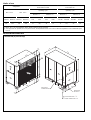
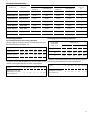
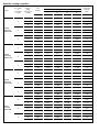
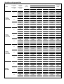
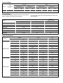
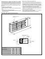
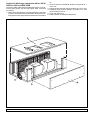
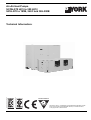
Air-Air Heat Pumps
SCOH-070 H(C) to 300 H(C)/
SICH-070 to 180B, 240C and SIH-300B
Ref.: TSCHCBE1
ER-028/1/91
ACCORDING TO ISO 14001 STANDARDS
ACCORDING TO ISO 9001 STANDARDS
Technical Information:
E U R O V E N T
CERTIFIED PERFORMANCE
CGM-97/013
Clima Roca York S.L. is participating in the EUROVENT Certification Program.
Products are as listed in the EUROVENT Directory of Certified Products,
in the program AC1, AC2 and AC3.
1
Index
Page
Page
General information
3
Malfunctions
23
- General description
- Nomenclature
3
3
Technical specifications
3
-
23
23
24
24
24
24
- Mechanical specifications
3-4
- Operating diagram
4
- Physical data
5
- Limites of use
6
- General dimensions
6 - 12
- Process for transforming a horizontal discharge into a
vertical discharge (SICH-070, 076, 090, 120, 150B units)
13
- Variant chart
14
- Nominal characteristics
15
- Correcting factors
15
- Sensible cooling capacities
16 - 17
- Test conditions
18
- Nominal flows
18
- Indoor fan features
18 - 19
- Outdoor fan features
20
- Electrical characteristics
21
-
Indoor fan thermal switch
High and low pressure switches
Electric heating thermal switch (accessory)
Thermostat errors
Protection for defrost cycles
Protection for temperature
Open or short-circuit of outdoor or indoor,
liquid probe
Open or short-circuit of discharge probe
Signalling
Incidents
Faults
Reset
Wiring diagrams
30
- Standard accessories
- Hot water heat coil for SICH-070-076, 090-120 and 150B
30
31
Internal electric heaters for SICH-070 to 180B
32
22
-
22
22
22
22
22
22
22
-
22
Duct electric heaters for SICH-070B to 180B, 240C
and SIH-300B
Test button and LEDs
Configuration
22
- Microswitches
- Configuration of switches
- Configuration of accessories
23
23
23
Installation of accessories
23
- Tray heater
- Electric heating
- Indoor coil probe (SCOH-070H (C) to 120H (C))
23
23
23
2
26 - 29
Accessories
Operation
Indoor fan
Outdoor fan
Four-way valve
Compressor
Defrost
Start-up
End
24
24
24
24
24 - 25
25
-
Technical specifications
Assembly and general dimensions
General characteristics
Dimensions with packing and weights
Installation
Wiring diagrams
Technical specifications
General dimensions
General characteristics
Dimensions with packing and weights
Installation
Location of the heater
Wiring diagrams
Vertical air discharge conversion kit for:
SCOH-070H (C) to 120H (C) and
SCOC-076H (C) and 090H (C)
- Vertical air discharge conversion kit for:
SCOH-150H (C) to 300H (C) and
SCOC-150H (C) and 180H (C)
- Vertical air discharge conversion kit for:
SICH-180B to 240C and SIH-300B
32
32 - 33
33
33
34
35 - 36
37
37
37
38
38
38
39 - 40
41 - 42
43 - 44
45 - 46
47
General information
Technical specifications
General description
Mechanical specifications
The SCOH-H (C)/SICH, SIH heat pump models are air-air
units with centrifugal fans both in the indoor as well as the
outdoor units.
The SCOH-H (C) outdoor unit includes compressor, condensing
unit, centrifugal fan and controls. The SICH, SIH indoor units
include evaporating coil, filter and fan. If necessary, they can be
easily modified on job site so as to have a compact unit.
The outdoor unit can be installed either outdoors or indoors,
as it is protected to withstand outdoor conditions, while the
fans are of the centrifugal type and can accept ducts.
Supplied complete, factory tested and ready for installation
of either interior or duct electric heaters accessories.
Designed to achieve considerable savings in energy and a
long service life.
Start-up and automatic regulation of the temperature is carried out by means of a 24-volt ambient thermostat.
Compressor
Vertical hermetic alternative type, mounted on antivibratory
supports, specially designed for heat pump units with
oversizing of mechanical components and low consumption
motor.
The SCOH-070 H (C), 076 H (C), 090 H (C) and 120 H (C)
units have one compressor, while the SCOH-150 H (C), 180
H (C), 240 H (C) and 300 H (C) units have two compressors.
Supplied with a charge of special oil so as to avoid foaming.
With oil electric heater.
Nomenclature
Vertical air-air heat pump
with centrifugal fans
Compressor heater
Keeps the sump oil hot for easy start-up and avoiding oil
being dragged out of the compressor.
Suction accumulator
Fitted in the suction tubing of the compressor, it protects same
from slugging by avoiding oil leaving the compressor.
Coils
Of a large surface, made of grooved copper tubing and aluminium fins. Located inside the cabinet, and thus protected
against damage during transportation or installation.
Indoor fan (SICH-070 and 076 B)
A centrifugal fan driven by an independent motor and belt
drive is installed.
Nominal capacity:
Cooling
Heating
070 H(C) = 18 600 W - 19 000 W
076 H(C) = 21 000 W - 22 300 W
090 H(C) = 30 000 W - 33 500 W
120 H(C) = 33 100 W - 34 400 W
150 H(C) = 40 000 W - 44 000 W
180 H(C) = 54 000 W - 56 000 W
240 H(C) = 74 000 W - 70 000 W
300 H(C) = 89 000 W - 91 000 W
Voltage:
22 = 230.3.50
38 = 400.3.50
Edition
Indoor fan (SICH-090B, 120B, 150B, 180B, 240C and SIH300 B) and outdoor fan (SCOH-070 H (C), 076 H (C), 090 H
(C) and 120 H (C))
Two centrifugal fans with a common shaft and belt drive, driven
by one single motor and coupled to the single plenum, are
installed.
Outdoor fan (SCOH-150 H (C), 180 H (C), 240 H (C) and 300
H (C))
Two independent centrifugal fans are installed. Each one of
these is driven by an independent motor and coupled to the
single plenum.
Transmission from the motor to the fan is by belt drive.
These fans have sufficient available pressure for the installation of ducts and optional accessories.
Cooling circuit
Made of welded copper tubing and equipped with access connections on the high and low pressure sides.
Refrigerant
The SCOH-H (C) and SICH, SIH units are supplied with connections ready for welding. The refrigerant load should be carried
out completely on job site. See refrigerant loads in physical
data table. The refrigerant used is R-407C (R-22 can also be
used).
Dryer filter
Coupled to the cooling circuit to protect the refrigerant against
humidity.
Casing
Made of zinc-aluminium plated steel sheeting, primed and
enamelled in epoxy power for outdoor installation.
SCOH 070 22 E1
Complementary heaters
Of the open-air wire type for fast heat dissipation, avoiding
temperature inertia that could affect components.
3
Thermostat
The SCOH-H(C)/SICH-070 to 120B units include, as standard equipment, a ARTTH001S electronic thermostat. Nevertheless, upon request and as an accessory, the ARTTH003S
electronic thermostat can also be used, programmable for
one stage and with communication possibilities.
The SCOH-H(C)/SICH-150B, 180B, 240C and SCOH-H(C)/
SIH-300B units include a ARTTH003S thermostat.
To connect the thermostat to the Rolón board, screened
10x0.22 mm² communication cable should be used.
ARTTH001SThermostat
24 Vac digital electronic type. To control one cool stage and
one heat stage. Designed to give a precise control of the
ambient temperature and graphic information of the mode in
which the air conditioner is operating. This is a ProportionalDifferential-Integral response control and, in accordance with
the difference between the programmed temperature and the
ambient temperature, it varies the on-off cycles to between 3
and 7.5 cycles per hour. Allows AUTO/ON operation of the
indoor fan. See Operating and Maintenance Instructions.
Mode
Outdoor
Fan
Day/Night
Operating diagram
SICH-B, C, SIH-B
POSSIBILITY
AIR TO INTERIOR
INDOOR UNIT
FAN
INDOOR
AIR
Mode
Fan
Day/Night
AIR TO
INTERIOR
FILTER
COIL
OPTIONAL
COILS
SCOH-H (C)
POSSIBILITY AIR TO
EXTERIOR (OPTIONAL)
AIR TO
EXTERIOR
ARTTH003S Thermostat
Digital electronic type. To control two cool stages and two
heat stages. Programmable for one cool stage and one heat
stage only. Designed to give a precise control of the ambient
temperature and graphic information of the mode in which the
air conditioner is operating. This is a Proportional-DifferentialIntegral response control in accordance with the difference
between the programmed temperature and the ambient temperature. Allows communication with a PC and AUTO/ON
operation of the indoor fan. See Operating and Maintenance
Instructions.
4
FAN
OUTDOOR
AIR
COMPRESSOR
OUTDOOR UNIT
COIL
Physical data
Outdoor units
Model
Amount
Compressor
Power rating
Power supply
Power rating
Power supply
Outdoor
fan
kW
kW
Approx.
Weight
Refrigerant
load
SCOH090 H(C)
SCOH120 H(C)
SCOH150 H(C)
SCOH180 H(C)
SCOH240 H(C)
SCOH300 H(C)
1
1
1
1
2
2
2
2
5.1
6.2
7.1
9
2 x 5.1
2 x 7.1
2 x 10.4
2 x 14.3
2x4
2x4
230.3.50 or 400.3.50
1.5
V.ph.Hz
Motor r.p.m.
1.5
400.3.50
3
3
2 x 2.2
2 x 2.2
230.3.50 or 400.3.50
400.3.50
1 400
1 400
1 400
1 400
1 400
1 400
1 400
1 400
Diameter turbines
mm
270
270
320
320
320
380
380
380
Width turbines
mm
270
270
320
320
320
380
380
380
1
1
1
1
2
2
2
2
5 x 37
5 x 37
5 x 40
5 x 40
5 x 40
5 x 42
5 x 48
5 x 48
Tubing depth x height
Diameter tubing
Surface
Dimens.
with
packing
SCOH076 H(C)
V.ph.Hz
Amount
Outdoor
coil
SCOH070 H(C)
3/8"
m²
1.01
1.01
1.47
1.47
2 x 0.84
2 x 1.02
2 x 1.44
2 x 1.44
Height
mm
1 412
1 412
1 546
1 546
1 612
1 661
1 814
1 814
Width
mm
1 360
1 360
1 738
1 738
2 040
2 240
2 640
2 640
Depth
mm
883
883
883
883
883
883
973
973
Nett
kg
305
325
375
385
560
650
720
750
Gross
kg
309
329
379
389
564
654
724
754
Nominal load R-22
kg
8.4
9
14.5
14
9.9 x 2
9x2
13 x 2
16 x 2
Nominal load R-407C
kg
8.4
8.7
13.8
13
9.4 x 2
9x2
13 x 2
16 x 2
SICH-090B
SICH-120B
1.5
1.5
Indoor units
Model
SICH-070B
Power rating
Power supply
Indoor
fan
kW
V.ph.Hz
Approx.
Weight
SICH-150B
1.5
SICH-180B SICH-240C
3
230.3.50 or 400.3.50
SIH-300B
3
5.5
400.3.50
1 400
Diameter turbines
mm
320
320
320
320
320
320
380
380
Width turbines
mm
320
320
240
240
320
320
380
380
1
1
1
1
1
1
1
1
4 x 21
4 x 21
4 x 25
4 x 25
4 x 25
4 x 29
5 x 32
5 x 32
Tubing depth x height
Diameter tubing
Surface
Dimens.
with
packing
0.75
Motor r.p.m.
Amount
Indoor
coil
0.75
SICH-076B
3/8"
m²
0.57
0.57
0.84
0.84
1.11
1.40
1.76
1.76
Height
mm
760
760
833
833
833
935
950
950
Width
mm
1 444
1 444
1 825
1 825
2 125
2 390
2 800
2 800
Depth
mm
930
930
930
930
930
955
1 030
1 030
Nett
kg
120
120
165
165
195
240
310
310
Gross
kg
142
142
195
195
230
290
350
350
5
Limits of use
Voltage limits
Nom. 230 V
Air intake temperature
to the outdoor coil DB
Air intake temperature
to the indoor coil
Operating cycle
Operating cycle
Nom. 400 V
Minimum °C
Minimum Maximum
198
Minimum °C
Maximum °C
Maximum °C
Minimum
Maximum
Cool
Heat
Cool
Heat
Cool WB
Heat DB
Cool WB
Heat DB
342
436
19
-20(1)
46
24
14
10 (2)
22
25
254
Notes: WB = wet bulb. DB = dry bulb.
(1) Below -20°C, only the emergency electric heater (optional) remains operative.
(2) This equipment can operate, for a short period of time, at temperatures below 10°C so as to raise the temperature of the conditioned space
to 10°C.
General dimensions mm
SCOH-070 H (C) and 076 H (C)
8
4
72
14
30
13
69
268
10
60
37
7
14
1392
919
24
138
24
2
14
00
11
ELECTRICAL
CONNECTIONS
7
40
32
8
39
8
11
DRAIN PIPE
EXT.Ø 28.5
GAS CONNECTION 1 1/8"
LIQUID CONNECTION 1/2"
6
General dimensions mm
SCOH-090 H (C) and 120 H (C)
6
324
30
14
44
14
37
8
14
996
24
139
24
2
14
85
14
5
72
17
38
1
11
7
32
5
1526
39
36
DRAIN PIPE
EXT. Ø 28.5
7
ELECTRICAL
CONNECTIONS
32
36
5
39
DRAIN PIPE
EXT. Ø 28.5
GAS CONNECTION 1 1/8"
LIQUID CONNECTION 5/8"
7
General dimensions mm
SCOH-150 H (C)
30
67
1
86
23
389
18
1
10
37
61
8
0
15
139
997
24
24
65
60
18
8
72
20
40
5
11
3
32
2
1592
40
40
DRAIN PIPE
EXT. Ø 28.5
3
32
ELECTRICAL
CONNECTIONS
40
2
40
DRAIN PIPE
EXT. Ø 28.5
2 GAS CONNECTIONS 1 1/8"
2 LIQUID CONNECTIONS 1/2"
8
General dimensions mm
SCOH-180 H (C)
30
66
2
96
25
389
20
1
10
37
2
96
8
14
138
1047
24
24
65
60
20
7
77
22
39
4
11
3
32
1
1641
45
40
DRAIN PIPE
EXT. Ø 28.5
3
32
ELECTRICAL
CONNECTIONS
40
1
45
DRAIN PIPE
EXT. Ø 28.5
2 GAS CONNECTION 1 1/8"
2 LIQUID CONNECTION 5/8"
9
General dimensions mm
SCOH-240 H (C) and 300 H (C)
30
66
62
11
25
389
24
1
37
10
62
11
48
1200
1
138
24
24
65
60
24
7
85
4
11
26
39
3
32
1
1794
53
40
DRAIN PIPE
EXT. Ø 28.5
3
32
40
ELECTRICAL
CONNECTIONS
1
53
DRAIN PIPE
EXT. Ø 28.5
2 GAS CONNECTION 1 3/8"
2 LIQUID CONNECTION 7/8"
10
General dimensions mm
SICH- 070 and 076B
26.5
612
DRAIN, INT, R. 3/4" G.
25
1357
433
130
4
540
590
26.5
30
19
341
190
573
396
528
25
Ø 21
337
.5
LIQUID CONNECTION 1/2"
50
725
25
GAS CONNECTION 1 1/8
ELECTRICAL
CONNECTIONS
SICH-090 and 120B
DRAIN, INT. R. 3/4" G.
616
168
5
26.5
613
341
470
663
311
325
263
311
321
612
25
26.5
1738
25
19
30
Ø 21
337
.5
LIQUID
CONNECTIONS 5/8"
50
725
25
GAS CONNECTION 1 1/8"
ELECTRICAL
CONNECTIONS
SICH-150B
616
DRAIN, INT. R. 3/4" G.
198
5
26.5
613
396
341
510
321
415
263
396
612
25
26.5
2038
663
LIQUID
CONNECTIONS
(2) 1/2"
25
19
30
Ø 21
337
.5
725
50
GAS CONNECTIONS (2) 1 1 /8"
25
ELECTRICAL
CONNECTIONS
11
General dimensions mm
SICH-180B
26.5
ELECTRICAL CONNECTIONS Ø 38
563
218
6
25
25
26.5
26.5
341
80
102
762
80
563
321
709
396
396
100
2239
26.5
341
80
45
(2)LIQUID CONNECTIONS 5/8"
45
102
(2) GAS CONNECTION 1 1/8 "
630
32
147
DRAIN, INT. R. 3/4" G.
ON OPPOSITE SIDE
777
SICH-240C and SIH-300B
26
25
653
479
479
2589
25
25
25
45
ELECTRICAL CONNECTION Ø 38
80
348
470
100
102
45
DRAIN, INT. R. 3/4" G.
(OPPOSITE SIDES)
12
24
80
102
838
80
653
375
788
9
263
(2) LIQUID CONNECTION 7/8"
3
(2) GAS CONNECTION 1 /8 "
32
710
147
857
as indicated in the standard orientation figure.
Process for transforming a horizontal dis5Unscrew the fastener of the fan to its support ref. 5.
charge into a vertical discharge (SICH-070, 076, 090,
120, 150B units)
1- Remove the fastening screws from the side covers ref. 1
and 2 of the upper unit.
2- Remove the side covers ref. 1 and 2.
3- Loosen the screws that fasten the fan motor to its base,
and remove the transmission belt.
4- Through the side accesses, unscrew panels ref. 3 and 4,
6- Place panel ref. 3 in the previous position of panel ref. 4,
and place panel ref. 4 in the previous position of panel
ref. 3.
7- Tighten the screws of these panels, and the fan on support ref. 5.
8- Replace the transmission belt and fasten the motor to its
base.
9- Screw on side covers ref. 1 and 2.
Standard orientation
Orientation variable at job site
2
2
3
4
4
3
1
1
4
5
FASTENING
SCREW
3
3
20 mm
4
5
13
Variant chart
SCOH-070/076 H(C)
230.3.50
400.3.50
SCOH-090/120 H(C)
230.3.50
400.3.50
SCOH-150 H(C)
400.3.50
SICH-090/120 B
230.3.50
400.3.50
SICH-150 B
400.3.50
SCOH-180 H(C)
400.3.50
SICH-180 B
400.3.50
SCOH-240H(C)
400.3.50
SICH-240 C
400.3.50
SCOH-300 H(C)
400.3.50
14
SICH-070/076 B
230.3.50
400.3.50
SIH-300 B
400.3.50
Nominal characteristics
Summer
Outdoor unit
Indoor unit
Winter
Cooling
capacity W
Consumption W
Heating
capacity W
Available pressure
indoor fan
Pa
Consumption W
SCOH-070H (C)
SICH-070/076B
20 000
8 000
17 300
7 300
62
SCOH-0706H (C)
SICH-070/076B
22 500
9 500
22 300
7 700
62
SCOH-090H (C)
SICH-090/120B
30 000
11 000
33 500
12 700
75
SCOH-120H (C)
SICH-090/120B
32 000
13 700
37 000
15 200
75
SCOH-150H (C)
SICH-150B
44 000
16 500
44 000
16 200
75
SCOH-180H (C)
SICH-180B
49 000
24 400
51 000
21 000
80
SCOH-240H (C)
SICH-240C
74 000
30 800
74 000
26 000
80
SCOH-300H (C)
SIH-300B
86 000
36 800
88 000
34 000
80
Correcting factors
Correcting factors for heating capacities
Correcting factors for the cooling capacities
Cooling capacity correcting factors for flows that vary from
the nominal flows in the indoor coil.
Flow %
Total capacity
Sensible capacity
80
90
0.960
100
0.980
1
110
1.016
120
DB air intake
temperature
indoor unit °C
14
10
6
0
-8
23
1.20
1.04
0.96
0.77
0.58
20
1.25
1.10
1.00
0.80
0.69
17
1.30
1.13
1.04
0.83
0.63
130
1.032
1.046
0.945
0.973
1
1.038
1.075
1.118
Comp. absorb. power 0.980
0.990
1
1.009
1.017
1.025
Correction of the real temperature of the air intake to the
outdoor coil for flows that vary from the nominal flows.
Correction of the real temperature of the air intake to the outdoor coil for flows that vary from the nominal flows.
Flow %
Flow %
Correction in °C on real
temperature of air intake
to the outdoor coil
70
5
80
3
90
1.5
100
0
110
-1
WB air temperature
outdoor unit °C
70
80
90
100
110
-2
-1.5
-0.5
0
0.5
120 130
120 130
-2
-2.5
Correction in °C on real
temperature of air intake
to the outdoor coil
1
1.2
15
Sensible cooling capacities
Sensible capacity (W)
Model
Dry outdoor
air
temperature
°C (DB)
25
SCOH070 H(C)/
SICH-070B
35
45
25
SCOH076 H(C)/
SICH-076B
35
45
25
SCOH090 H(C)/
SICH-090B
35
45
25
SCOH120 H(C)/
SICH-120B
35
45
16
Humid air
intake
temperature
°C (WB)
Total
capacity
Compressor
absorbed
power
Dry air intake temperature to the coil °C (DB)
22
24
27
29
W
W
W
W
W
kW
22
22 560
6 806
9 605
13 802
16 604
5.54
19.5
20 304
10 305
13 104
17 301
20 104
5.81
17
18 800
14 018
16 816
18 800
18 800
6.07
22
20 868
6 239
9 037
13 235
16 033
6.27
19.5
18 800
9 754
12 552
16 750
18 800
6.60
17
17 296
12 687
15 486
17 296
17 296
6.93
22
18 800
5 608
8 406
12 603
15 401
7.26
19.5
16 920
9 125
11 923
16 120
16 920
7.59
17
15 416
12 668
15 416
15 416
15 416
7.92
22
25 440
7 792
10 590
14 787
17 590
6.59
19.5
22 896
11 273
14 071
18 268
21 071
6.91
17
21 200
15 000
17 798
21 200
21 200
7.22
22
23 532
7 136
9 934
14 132
16 930
7.46
19.5
21 200
10 637
13 436
17 633
20 431
7.85
17
19 504
13 484
16 282
19 504
19 504
8.24
22
21 200
6 408
9 206
13 403
16 201
8.64
19.5
19 080
9 913
12 711
16 908
19 080
9.03
17
17 384
13 448
16 246
17 384
17 384
9.42
22
36 360
10 866
15 763
23 109
28 013
6.89
19.5
32 724
17 006
21 904
29 250
32 724
7.22
17
30 300
23 487
28 384
30 300
30 300
7.54
22
33 633
9 965
14 863
22 209
27 107
7.79
19.5
30 300
16 130
21 028
28 374
30 300
8.20
17
27 876
21 161
26 059
27 876
27 876
8.61
22
30 300
8 961
13 859
21 205
26 103
9.02
19.5
27 270
15 128
20 026
27 270
27 270
9.43
17
24 846
21 337
24 846
24 846
24 846
9.84
22
40 080
12 147
16 937
24 121
28 917
9.24
19.5
36 072
18 128
22 917
30 102
34 899
9.68
17
33 400
24 490
29 280
33 400
33 400
10.12
22
37 074
11 132
15 921
23 106
27 896
10.45
19.5
33 400
17 142
21 931
29 116
33 400
11.00
17
30 728
21 267
26 057
30 728
30 728
11.55
22
33 400
10 002
14 792
21 976
26 766
12.10
19.5
30 060
16 017
20 806
27 991
30 060
12.65
17
27 388
22 077
26 867
27 388
27 388
13.20
Sensible cooling capacities
Sensible capacity (W)
Model
Dry outdoor
air
temperature
°C (DB)
25
SCOH150 H(C)/
SICH-150B
35
45
25
SCOH180 H(C)/
SICH-180B
35
45
25
SCOH240 H(C)/
SICH-240C
35
45
25
SCOH300 H(C)/
SIH-300B
35
45
Humid air
intake
temperature
°C (WB)
Total
capacity
Compressor
absorbed
power
Dry air intake temperature to the coil °C (DB)
22
24
27
29
W
W
W
W
W
kW
22
48 360
14 455
20 954
30 703
37 211
10.68
19.5
43 524
22 604
29 103
38 852
43 524
11.19
17
40 300
31 204
37 703
40 300
40 300
11.70
22
44 733
13 257
19 756
29 505
36 004
12.08
19.5
40 300
21 438
27 937
37 686
40 300
12.72
17
37 076
28 104
34 603
37 076
37 076
13.36
22
40 300
11 922
18 421
28 170
34 669
13.99
19.5
36 270
20 105
26 604
36 270
36 270
14.63
17
33 046
28 343
33 046
33 046
33 046
15.26
22
65 160
19 610
27 865
40 247
48 513
15.40
19.5
58 644
29 940
38 195
50 578
58 644
16.13
17
54 300
40 885
49 140
54 300
54 300
16.86
22
60 273
17 978
26 233
38 616
46 871
17.41
19.5
54 300
28 354
36 609
48 991
54 300
18.33
17
49 956
36 680
44 936
49 956
49 956
19.25
22
54 300
16 160
24 415
36 798
45 053
20.16
19.5
48 870
26 542
34 797
47 179
48 870
21.08
17
44 526
36 997
44 526
44 526
44 526
22.00
22
89 280
27 105
37 625
53 405
63 939
17.37
19.5
80 352
40 233
50 753
66 533
77 070
18.20
17
74 400
54 214
64 734
74 400
74 400
19.03
22
82 584
24 837
35 357
51 137
61 657
19.65
19.5
74 400
38 032
48 551
64 331
74 400
20.68
17
68 448
49 864
60 383
68 448
68 448
21.71
22
74 400
22 314
32 834
48 614
59 133
22.75
19.5
66 960
35 520
46 040
61 819
66 960
23.78
17
61 008
48 828
59 348
61 008
61 008
24.82
22
107 280
32 678
44 991
63 460
75 790
23.13
19.5
96 552
48 026
60 339
78 808
91 142
24.24
17
89 400
64 404
76 717
89 400
89 400
25.34
22
99 234
29 938
42 251
60 270
73 033
26.16
19.5
89 400
45 368
57 681
76 150
88 463
27.54
17
82 248
58 814
71 127
82 248
82 248
28.92
22
89 400
26 891
39 204
57 673
69 986
30.29
19.5
80 460
42 336
54 649
73 118
80 460
31.67
17
73 308
57 905
70 218
73 308
73 308
33.05
17
Test conditions
Summer
Voltage
Length
interconnecting
tubing
400
7.5 metros
Outdoor temp. °C
Winter
Indoor temp. °C
Outdoor temp. °C
Indoor temp. °C
DB
WB
DB
WB
DB
WB
DB
WB
35
24
27
19
7
6
20
12
Nominal flows
The cooling and heating capacities of the corresponding tables are valid for the following nominal flows.
For other flows, apply the correcting factors from the corresponding table.
Indoor fan
available pressure
Nominal flow
Model
m3/h
m3/s
Pa
SICH-070 & 076B
4 530
1.26
62
SICH-090 & 120B
8 500 / 8 300
2.36 / 2.31
62 / 75
SICH-150B
10 700
2.97
75
SICH-180B
13 600
3.77
80
SICH-240C
16 500
4.58
80
SIH-300B
19 500
5.42
80
Indoor fan features
Static pressure
available (1)
Model
SICH-070-076B
Absorbed
power
Air flow
mm WG
Pa
m3/h
m3/s
W
14
137.2
3 200
0.89
605
12
117.6
3 580
0.99
680
10
98
3 930
1.09
735
8
78.4
4 260
1.18
795
6.3
61.7
4 530
1.26
860
6
58.8
4 570
1.27
865
4
39.2
4 860
1.35
935
2
19.6
5 120
1.42
990
0.0
0.0
5 360
1.49
1 035
17
166.8
6 320
1.76
1 300
16
157
6 590
1.83
1 340
14
137
7 080
1.97
1 470
12
118
7 500
2.08
1 570
10
98
7 900
2.19
1 680
7.6
75
8 300
2.31
1 770
6.3
62
8 500
2.36
1 840
4
39
8 800
2.44
1 935
2
19.6
9 070
2.52
2 010
0.0
0.0
9 270
2.58
2 075
SICH-090-120B
18
Indoor fan features
Static pressure
available (1)
Model
Absorbed
power
Air flow
mm WG
Pa
m3/h
m3/s
W
17.9
175.4
7 000
1.94
896
17.1
167.6
7 500
2.08
970
16.0
156.8
8 000
2.22
1 045
14.8
137.2
8 500
2.36
1 100
13.3
130.3
9 000
2.50
1 175
12.1
118.6
9 500
2.64
1 275
10.0
98.0
10 000
2.78
1 375
8.5
83.3
10 500
2.92
1 450
6.5
63.7
11 000
3.05
1 600
4.3
42.1
11 500
3.19
1 700
2.0
19.6
12 000
3.33
1 802
0.0
0.0
12 500
3.47
1 970
15.9
155.8
11 500
3.19
2 004
14.2
139.1
12 000
3.33
2 139
12.6
123.4
12 500
3.47
2 240
11.0
107.8
13 000
3.61
2 408
8.6
84.2
13 500
3.75
2 535
6.5
63.7
14 000
3.89
2 732
3.9
38.2
14 500
4.02
2 843
1.3
12.7
15 000
4.16
3 000
0.0
0.0
15 200
4.22
3 150
20
196
12 900
3.58
2 200
16
157
14 000
3.89
2 800
12
118
15 300
4.25
3 120
8
78
16 500
4.58
3 500
6
59
17 100
4.75
3 650
4
39
17 700
4.92
3 800
0.0
0.0
19 000
5.28
4 100
30
294.3
12 800
3.56
3 105
24
235.4
14 600
4.06
3 900
20
196
16 000
4.44
4 300
16
157
17 100
4.75
4 805
12
118
18 350
5.10
5 110
8
78
19 500
5.42
5 520
6
59
20 000
5.56
5 800
4
39
20 700
5.75
6 000
0
0
22 300
6.19
6 300
SICH-150B
SICH-180B
SICH-240C
SIH-300B
(1) Values calculated with humid coil, including filters.
19
Outdoor fan features
Static pressure
available
Air flow
Absorbed
power
Model
SCOH-070H (C)
SCOH-076H (C)
SCOH-090H (C)
SCOH-120H (C)
mm WG
Pa
m3/h
m3/s
W
18
177
3 380
0.94
730
16
157
4 050
1.13
830
12
118
5 050
1.40
970
8
78
5 820
1.62
1 050
5.1
50
6 300
1.75
1 130
4
39
6 470
1.80
1 160
0.0
0.0
7 010
1.95
1 270
18
177
8 200
2.28
1 690
14
137
9 750
2.71
1 900
12
118
10 230
2.84
2 020
10
98
10 700
2.97
2 130
8
78
11 100
3.08
2 230
6
59
11 500
3.19
2 330
5.1
50
11 650
3.24
2 380
4
39
11 800
3.28
2 430
2
19.6
12 200
3.39
2 540
0.0
0.0
12 500
3.47
2 600
20
196
9 200
2.56
2 430
16
157
10 300
2.86
2 710
12
118
11 200
3.11
2 920
10
98
11 600
3.22
3 040
8
78
12 000
3.33
3 180
6
59
12 400
3.44
3 290
5.1
50
12 600
3.50
3 360
4
39
12 900
3.58
3 430
2
19.6
13 300
3.69
3 550
0.0
0.0
13 700
3.81
3 630
20
196
14 000
3.89
3 760
16
157
15 100
4.19
4 100
14
137
15 700
4.36
4 300
10
98
16 800
4.67
4 630
8
78
17 300
4.81
4 820
5.1
50
18 100
5.03
5 070
2
19.6
18 800
5.22
5 350
0.0
0.0
19 300
5.36
5 500
20
196
20 500
5.69
6 740
16
157
21 600
6.00
72 00
12
118
22 600
6.28
76 00
8
78
23 400
6.50
8 000
4
39
24 100
6.69
8 400
0.0
0.0
24 800
6.89
8 800
SCOH-150H (C)
SCOH-180H (C)
SCOH-240H (C)
SCOH-300H (C)
20
Electrical characteristics
Outdoor units
Power supply V.ph.Hz.
Consumption A
Model
Compressor
Compressor
Fan
Fan
Start
Nominal
Start
Nominal
Power
Automatic
supply cable
switch
section (2) (K curve)(1)
mm2
A
230.3.50
230.3.50
166
24.1
23
4.9
6
32
400.3.50
400.3.50
94
14.6
17
2.8
4
20
230.3.50
230.3.50
210
31.2
23
4.9
10
40
400.3.50
400.3.50
116
17.9
10
2.8
4
25
230.3.50
230.3.50
224
31.5
53
8.5
16
63
400.3.50
400.3.50
127
18.1
31
4.9
6
32
230.3.50
230.3.50
279
45.2
53
9.7
16
63
400.3.50
400.3.50
158
25.6
31
5.6
10
40
SCOH-150H (C)
400.3.50
400.3.50
2 x 94
2 x 14.6
2 x 17
2 x 3.9
10
50
SCOH-180H (C)
400.3.50
400.3.50
2 x 127
2 x 16.9
2 x 30
2 x 4.3
16
63
SCOH-240H (C)
400.3.50
400.3.50
2 x 158
2 x 18.8
2 x 38
2 x 7.4
25
80
SCOH-300H (C)
400.3.50
400.3.50
2 x 189
2 x 25.8
2 x 38
2 x 7.4
35
100
SCOH-070H (C)
SCOH-076H (C)
SCOH-090H (C)
SCOH-120H (C)
Important: The dimensioning of the automatic switch and power supply line sections are orientative and should be corrected in accordance with
job site conditions, length between units and legislation in force.
Notes: 1.- K curve (DIN, VDE 0660-104). 2.- Based on copper conductors.
Indoor units
Power supply V.ph.Hz.
Consumption A
Fan
Model
Fan
Power
supply cable
section
mm2
Start
Nominal
230.3.50
14
3.4
4 x 1.5
400.3.50
8
2.2
4 x 1.5
230.3.50
30
5.5
4 x 1.5
400.3.50
17
3.2
4 x 1.5
230.3.50
30
5.8
4 x 1.5
400.3.50
17
3.4
4 x 1.5
SICH-150B
400.3.50
20
3.7
4 x 1.5
SICH-180B
400.3.50
34
6.1
4 x 1.5
SICH-240C
400.3.50
36
6.8
4 x 1.5
SIH-300B
400.3.50
68
9.8
4 x 2.5
SICH-070/076B
SICH-090B
SICH-120B
Important: The dimensioning of the automatic switch and power supply line sections are orientative and should be corrected in accordance with
job site conditions, length between units and legislation in force.
21
Operation
The control board of these units is common to both the cool
only as well as the heat pump units. By connecting an additional module, two-compressor equipment can be controlled.
Equipment control is carried out by means of software that is
resident in the board. System operation is carried out in accordance with the position of the microswitches in the main
board. There are also variations in the control algorithm, depending upon the accessories the board detects installed in
the equipment.
pressor, along with the outdoor fan, does not start until after a
minimum off time, so as to avoid consecutive start-ups. This
period of time can be set by means of microswitches SW4;
ON = 2' and OFF = 5'.
In two-stage equipment, the first compressor to start up will
be the one that has been less hours in operation.
The second compressor will start if a Y2 signal is received
from the thermostat.
Whenever one of the compressors is to turn off, it will be the
one that has been most hours in operation.
Defrost
The defrost cycle is possible only in heat pump operation.
In two-stage units, simultaneous defrost of both stages is not
allowed, one remaining in standby until the other one has finished.
Start-up
J3
J8
J10
K6
J4
J5
J6
J1
J9
8
S1
1
ON OFF
SN
J7
K1
ROLON
V3
V1
V2
K4
K3
K5
006791200
CTI013B
TEST
X2 X1 L2 W O/B Y2 Y1 G
X
R
X2 X1 L2 W O/B Y2 Y1 G
X
R
The following conditions should apply:
1) The compressor is on.
2) The liquid probe temperature is below -3°C for 3'.
3) If outdoor temperature is below 0°C, after compressor startup 5' are timed before activating the defrost cycle.
When the defrost cycle is started, the board carries out the
following operations:
1) Sets the 4-way valve to cool mode.
2) Turns the outdoor fan off.
3) Activates the following heat-generating phase, if the thermostat requires heat.
4) Turns the indoor fan off if there is no next heat stage.
5) Does not turn off the compressor that is defrosting, even if
indicated by the thermostat.
REV. 1.0
End
Indoor fan
Operation can be continuous or automatic. For continuous
operation, select said operation on the thermostat.
If the internal probe (optional accessory) is installed, and the
operating mode is heat, the fan will not start until the indoor
coil has reached 35°C and will stop when this temperature
drops to below 30°C. Whenever the electric heating starts,
the indoor fan will also start.
Outdoor fan
The outdoor fan starts 5 seconds before the compressor. And
stops after the compressor stops.
Four-way valve
When SW6 of the control board is set to ON, the four-way
valve activates when the thermostat requests heat. When a
defrost cycle is carried out, this valve operates inversely;
that is to say, in cool.
Compressor
When signal Y1 is present, the board commands the outdoor
fan to become operative, and then the compressor. The com22
This operation will last until one of the following conditions is
completed:
a) Liquid temperature above 13°C during 2".
b) Liquid temperature above 5°C during 30".
c) Timing period after defrost start-up over 10'.
d) Failure signal from high pressure switch.
Once defrost is over:
1) Sets four-way valve to heat.
2) Turns outdoor fan on.
3) Starts indoor fan if no next heat stage exists.
4) Turns off heat generating phase that started due to the
defrost cycle.
Test button and LEDs
Pressing the Test button shortens certain timings, resets the
unit after any failure is detected, and also acts as a LonWorks
service pin.
There are three signalling led diodes:
a) The green led indicates correct operation of the equipment
and incidents. If the equipment is operating correctly, this
led flashes at a frequency of 1.6 Hz.
b) The red led indicates failures. If no failure is present, this
led remains off.
c) The yellow led is the LonWorks service led, and also indicates, by flashing, that the operating compressor is timed.
Configuration
Each time the electronic board is powered, system configuration will be checked, with the exception of the accessories.
Below we can see how the different options are configured.
Microswitches
Installation of accessories
They are read after power supply connection, and the board
will act in accordance with their position. SW1 and SW2 set to
OFF indicates that the configuration is carried out by remote
control, and the parameters stored in the EEPROM memory
are use.
The accessories are used to support extended functions of
the unit.
Said accessories can be either factory mounted or installed
by the client. Power supply to the unit should always be disconnected. The accessory, along with the necessary elements,
will then be assembled, and the power supply connected once
again.
Once the search and configuration sequence is carried out,
the new elements will be recognised and they will begin to
operate.
The function of the different accessories is defined below.
Configuration of switches
The microswitches establish the following configurations:
Number State
Meaning
OFF/OFF Ignore SW, programs communication routes
1/2
3
4
5
Defrost period 30'
OFF/ON
Defrost period 60'
ON/ON
Defrost period 90'
ON
Indoor fan ON during defrost
OFF
Indoor fan OFF during defrost
ON
Compressor delay 2'
A cable heater is used, mounted between the lower area of
the outdoor coil and the tray, where the defrost water is collected. Its function is to avoid freezing of the water in the tray
and ice in the lower area of the coil.
This heater should be activated in the winter cycle, while the
compressor is operative, and when the liquid temperature is
below -2°C; and disactivated when the temperature is above
2°C.
OFF
Compressor delay 5'
Electric heating
ON
Cool mode
OFF
Heat pump mode
ON
4-way valve active in heat
OFF
4-way valve active in cool
ON
Receives signal B from thermostat (active in heat)
OFF
Receives signal O from thermostat (active in cool)
ON
NA
OFF
NA
6
7
8
Tray heater
ON/OFF
In the case of the heaters, the relay is used to switch the
power contactor on and off, as well as the thermal switch with
safety automatic reset.
In one-stage equipment, the response to a demand for first
stage from the thermostat starts the compressor stage, and
the second starts the electric heating.
In the case of a failure in the compressor stage, the electric
heating would be activated as the first stage.
Whenever the electric heating is on, the indoor fan will also be
operative.
Indoor coil probe (SCOH-070 to 120H (C))
Configuration of accessories
To carry out an accessory search and configuration, the test
button should be pressed for over two seconds, until the red
led goes on. Once the search and configuration process begins, the red led on the board goes on, and stays on until the
operation is concluded. Once off, the board uses the accessories found.
Said search will also determine which optional probes are
connected to the board. A incident will be give if one of the
optional probes detected in the configuration process does
not give valid values.
The following table shows the probe configuration.
Pump
Probe
Obligatory
Optional
The probe in the indoor coil, depending upon the temperature,
carries out the following operations:
1) If in heat operating mode, and the electric heater is not
activated, the fan will not start until the indoor coil reaches
35°C. If the electric heating is not activated, the indoor fan
will turn off if the temperature drops below 30°C. If once
the compressor is operating in heat mode for 2' the indoor
temperature does not reach over 35°C, an unrecoverable
heat temperature incidence is indicated.
2) If in cool operating mode, and the probe temperature is
below -25°C, or the compressor is in operation for over 5'
and the temperature is below -4°C, the compressor and
outdoor fan go off. After the timed period, the compressor
starts again. If this is repeated 3 times in 35 minutes, a
failure of repeated start-up in cool is indicated, and the
compressor will not restart.
Malfunctions
Discharge
x
Liquid
x
There are two different types of malfunctions: incidents that
do not turn the unit off, and failures or lockouts, that inactivate the unit.
Outdoor
x
Indoor fan thermal switch
Suction
x
Its activation turns the entire unit off, and an indoor fan thermal switch failure is indicated.
Indoor coil
x
High and low pressure switches
Its activation turns the compressor and outdoor fan off. A
23
high or low pressure switch failure is indicated.
Electric heating thermal switch (accessory)
Activation turns the electric heating off and indicates an incident. If this error occurs more than 3 times in an hour, an
electric heater thermal switch incident is indicated, it is inhibited, and the electric heater is turned off.
Thermostat errors
If signal Y is given without signal G, it acts as if signal G were
active. An incident of signal Y1 without signal G is indicated.
If signal W is given without signal G, it acts as if signal G
were active. An incident of signal W without signal G is given.
If signal W is given without signal B/O, it acts as if signal B/O
were indicating heat mode. An incident of signal W without
signal B/O is given.
indicates the type of incident. Another short pause. The third
indicates the incident detected, followed by a long pause,
and the sequence is repeated again as long as the incident
lasts.
The incidents reset when the cause disappears. In the case
of more than once incident at the same time, only the first
one detected and not reset is indicated. As they reset, the
other existing incidents not reset will be indicated.
The following table shows the possible errors:
Type
Flashes
Incident
2nd
3rd
1
1
Discharge probe open or >150ºC
1
2
Liquid probe open or short circuited
1
3
Outdoor probe open or short circuited
1
4
Indoor probe open or short circuited
1
5
Outdoor temperature too low
2
1
Signal Y1 or Y2 without signal G
2
2
Signal W without signal B
2
3
Signal W without signal G
2
4
Signal Y2 without signal Y1
3
1
Electric heater thermal switch AUX1
3
2
Electric heater thermal switch AUX2
3
3
Electric heater thermal switch EM1
3
4
Electric heater thermal switch EM2
Open or short circuit of the outdoor or indoor
liquid probe
4
1
Repeated defrost cycles
An incident of the corresponding probe is indicated if the value
read is below -40°C, or above 100°C. If this incident takes
place in heat mode in the liquid probe, repeated defrost cycles are carried out with a maximum duration of 30 seconds.
Temperature 4
2
Discharge temperature does not recover
4
4
Temperature in heat does not recover
5
1 ID of trasceiver inknown
Open or short circuit of discharge probe
Others
5
2
Protection for defrost cycles
If 3 consecutive defrost cycles are carried out and ended in
compliance with the 10' timer, an incident of repeated defrosts
is indicated. This incident is deleted when a defrost cycle is
ended in compliance with another condition that is not the
maximum timer period.
Probes
Protection for temperature
a) If the outdoor temperature is below -20°C, the compressor
turns off. An incident of low outdoor temperature (only in
heat mode) is indicated.
b) If the discharge temperature is above 130°C, the compressor and outdoor fan turn off. An excessive discharge
temperature failure is indicated.
c) If while the compressor is on for 5', the discharge temperature does not rise above 50°C, in cool mode, or 35°C
in heat mode, a low discharge temperature incident is indicated.
d) If the suction temperature is very low, the compressor and
outdoor fan turn off. If this is repeated 3 times in 35 minutes, a failure is indicated.
e) If, in heat mode, the liquid temperature is below -30°C, the
compressor and outdoor fan turn off, and a failure is indicated.
An incident of the discharge probe is indicated if its value is
below -20°C, or above 150°C. If the probe is short circuited, a
failure is indicated.
Signalling
Malfunction signalling is carried out at two levels. One for
incidents and another for failures.
Incidents
Incidents do not turn the unit off, and are indicated by the
green led on the electronic board. If there is no failure present,
this led flashes at a frequency of 1 Hz.
When an incident occurs, the led flashes in three sequences.
The first indicates the compressor involved: one flash for stage
1, and two for stage 2, followed by a short pause. The second
24
Thermostat
Electric
heater
Accessory disappeared
Failures (lockouts)
Failures or lockouts turn the unit off.
They are indicated by the red led on the board, and by means
of the thermostat (depending upon the model). Relay K6 of
the board is also activated with a 24 VAC signal between
terminals LED2 and B of J2. If no failure is present, this led
remains off. When a failure takes place, this led flashes in
two sequences. The first indicates the compressor involved:
one flash for stage 1 and two for stage 2, followed by a short
pause. Then the detected failure is indicated, followed by a
long pause and the sequence is repeated.
Should more than one alarm take place, only the first one
detected and not reset is indicated.
The following table shows the possible failures:
Flashes
Meaning
1
Discharge temperature surpassed or probe short
circuited
2
High pressure switch, outdoor fan thermal switch or compressor module thermal switch
3
Low pressure switch
4
Indoor fan thermal switch
5
Repeated star-ups in cool or suction temperature <-25ºC
6
Low liquid temperature <-30ºC
Reset
The incidents, with a few exceptions, do not need to be reset.
They reset automatically once the cause has disappeared.
The following incidents require resetting, and are reset in the
same way as the alarms:
a) Accessory disappeared.
b) Repeated defrost cycles (also reset if a defrost cycle ends
under normal conditions)
c) Electric heating thermal switch.
The alarms can be reset as follows:
1) Setting the thermostat to OFF, if communication with the
thermostat has been implemented.
2) Pressing the reset button on the electronic board.
3) Disconnecting and reconnecting power supply to the electronic board.
4) By means of the communications trunk.
It is worth pointing out that, with a reset by means of setting
the thermostat to OFF, the board cannot be reset more than 3
times a day.
25
26
Q2
(6)
4
2
M
3~
4
3
6
5
(8)
KM3
4
2
6
5
6
OUTDOOR
FAN
M3
M
3~
3
4
1
2
E3
14 22
13 21
R1
KM1
(6)
22
N
X3...
S2
S1
5
6
7
7
8
8
8
ARTTH003S
ARTTH001S
T-11
M1
0V
230V
80 VA
T1
2
B
X2...
0V
24V
1
(02)
F2
14
13
X2...
R
X
P
LP
2
1
(03)
F3
A2
(2)
P
HP
2
1
3
2
1
14
13
F3
M2
M1
2
1
3
J1
4
1
3
5
21
R
5
1
KM2
A2
2
4
6
14
1
3
5
13
3
5
1
3
5
13
A1
INDOOR FAN
MOTOR GUARD
4
(03)
1
RV
2
J5
RS-485
SECOND
COMPRESSOR
ACCESORIES
J9
J10
J6
J8
I-2150b
SCOH-070H(C), 076H(C), 090H(C)
and 120H(C)
400.3.50
(02)
2
4
6
14
KM3
A2
J4
B4
B3
4
9
B2
J3
8
B1
A1
2
J7
7
2
4
(01)
6
22 (1)
KM1
A2
A1
ELECTRONIC BOARD A1
J2
X2 X1 L2 W O/B Y2 Y1 G
B R
Y G
R
1
R
4 5 8
O P G
X
W O
3
B
X2 X1 L2 W B Y2 Y1 G
OUTDOOR FAN
MOTOR GUARD
THE COMPONENTS INCLUDED IN THESE BOXES
ARE NOT SUPPLIED BY THE MANUFACTURER.
(5)
A2
M2
T1
T2
3A
F1
R
X2...
SCREENED
CALBE
''S1 CONFIGURATION OF 10x0,22 mm 2
BOARD A1, DEPENDING
UPON THERMOSTAT TO BE
INSTALLED
4
3
2
6
7
HIGH AND LOW
PRESSURE SWITCH
-INDOOR FAN "M2" IS TO BE CONNECTED AT JOB SITE. SEE
ELECTRICAL CHARACTERISTICS TABLE.
E2
14 22
13 21
F3
5
21
2
L
1
5
6
6
4- WAY VALVE
NOTE:
M2
2
1
INDOOR FAN
(7)
KM2
6
5
M1
6
5
4
3
COMPRESSOR
M
3~
3
2
1
3
F4
1
X3...
OFF
4
3
2
5
THERMOSTATS
5
BLACK
1A
6,5
6,5
3,1
4
3
2
4
GREEN
1
F2
1
4,5
4,5
2,5
1
1
S1
3
SUCTION PROBE
WHITE
KM1
EO
5x10
5x6
5x4
ON
OFF
ON
OFF
ON
2
LIQUID PROBE
YELLOW
X1... L1 L2 L3 N
40
32
SCOH-120 H(C)
25
SCOH-076 H(C)
20
SCOH-090 H(C)
Q2 (A)
MODEL
SCOH-070 H(C)
1
SECTION" F2 (A) REG. F3 (A) REG.
B" mm2
3,1
2,5
5x4
(03)
DISCHARGE PROBE
E1
L1 L2 L3 N
INSTALL AT
JOB SITE
(02)
OUTDOOR PROBE
Sección "B" mm 2 Cu
Q1
L1 L2 L3 N
400V, 3~ , 50Hz, N, PE
(01)
Wiring diagram
SCOH-070H(C), 076H(C), 090H(C) and 120H(C), 400.3.50
COMPRESSOR
MODULE
SUMP HEATER
Q2
L1 L2 L3
(6)
4
2
M
3~
4
3
6
5
(8)
KM3
4
2
6
5
6
5
OUTDOOR
FAN
M3
M
3~
3
4
1
2
3
E3
14 22
13 21
R1
KM1
(6)
X3...
L2
1
2
22
21
1
2
4
3
5
6
6
7
7
7
8
8
8
S2
S1
T2
M1
(5)
A2
M2
T1
L
X3...
0V
230V
" S1" CONFIGURATION OF
BOARD A1, DEPENDING
UPON THERMOSTAT TO BE
INSTALLED
COMPRESSOR
MODULE
SUMP HEATER
80 VA
T1
3A
F1
B
X2...
0V
24V
1
2
R
X2...
(02)
F2
SCREENED
CABLE
10x0,22 mm 2
ARTTH003S
ARTTH001S
T-11
14
13
X2...
P
LP
2
1
(03)
F3
A2
(2)
P
HP
2
1
3
2
1
14
13
F3
M2
M1
2
1
3
J1
4
1
3
5
21
R
5
A1
1
KM2
A2
2
4
6
14
1
3
5
13
3
4
5
4
(02)
2
4
6
14
(03)
1
RV
2
J5
RS-485
SECOND
COMPRESSOR
ACCESSORIES
J9
J10
J6
J8
I-2152b
SCOH- 070H(C), 076H(C), 090H(C)
and 120H(C)
400.3.50
1
3
5
13
A1
KM3
A2
J4
B4
B3
9
B2
J3
8
B1
A1
2
J7
7
2
4
(01)
6
22 (1)
KM1
A2
ELECTRONIC BOARD
A1
R
J2
X
B R
Y G
X2 X1 L2 W O/B Y2 Y1 G
1
R
5 8
P G
R
4
O
6
X
W O
3
B
THERMOSTATS
5
X2 X1 L2 W B Y2 Y1 G
THE COMPONENTS INCLUDED IN THESE BOXES
ARE NOT SUPPLIED BY THE MANUFACTURER.
OFF
ON
5
6
INDOOR FAN
MOTOR GUARD
-INDOOR FAN "M2" IS TO BE CONNECTED AT JOB SITE.
SEE ELECTRICAL CHARACTERISTICS TABLE.
E2
14 22
13 21
F3
1
F4
1A
10,2
10,2
5,4
5
4
3
5
4
4-WAY VALVE
NOTE:
INDOOR
FAN
2
1
COMPRESSOR
E1
(7)
KM2
M2
6
5
6
M1
M
3~
3
4
5
6,5
6,5
4
4
F2 (A) REG. F3 (A) REG.
4
3
S1
3
BLACK
2
3
4x25
4x16
4x10
4x6
SECTION
"B" mm2
2
2
2
SUCTION PROBE
GREEN
1
F2
1
63
63
SCOH-090H(C)
SCOH-120H(C)
40
SCOH-076H(C)
32
Q2 (A)
1
OFF
ON
1
OFF
ON
1
LIQUID PROBE
WHITE
KM1
EO
MODEL
SCOH-070H(C)
(03)
DISCHARGE PROBE
YELLOW
X1... L1 L2 L3
INSTALL AT JOB SITE
(02)
OUTDOOR PROBE
Sección "B" mm 2 Cu
Q1
L1 L2 L3
230V, 3~ , 50Hz, PE
(01)
Wiring diagram
SCOH-070H(C), 076H(C), 090H(C) and 120H(C), 230.3.50
HIGH AND LOW
PRESSURE SWITCH
OUTDOOR FAN
MOTOR GUARD
27
28
Q2
4
2
2
1
2
1
M
3~
4
3
4
3
6
5
6
5
E2
-INDOOR FAN "M3" IS TO BE CONNECTED AT JOB SITE.
SEE ELECTRICAL CHARACTERISTICS TABLE.
M3
M
3~
4
3
4
3
6
5
6
5
INDOOR
FAN
2
1
2
1
50
63
SCOH-150H(C)
SCOH-180H(C)
1
E3
M4
M
3~
4
3
6
5
OUTDOOR
FAN-1
2
1
E4
(19)
KM5
M5
M
3~
4
3
4
3
6
5
6
5
OUTDOOR
FAN-2
2
1
2
1
32
32
F5
(16)
7
11
32
32
E5
14 22
13 21
8,5
8,5
4,5
4,5
F4 (A)
REG.
THE COMPONENTS INCLUDED IN THESE BOXES
ARE NOT SUPPLIED BY THE MANUFACTURER.
(13)
KM4
6
5
7
14 22
4
3
5
20
25
20
25
14 22
2
1
5x35
5x25
F3 (A)
REG.
F2(A)
(05)
F1(A)
13 21
SCOH-300H(C)
5x16
5x10
SECTION
"B" mm2
13 21
80
100
SCOH-240H(C)
F4
(9)
Q2 (A)
MODEL
(04)
2A
F9
X3..
8,5
8,5
4,5
4,5
F5 (A)
REG.
1
L
1
2
S1
M1
(3)
A3
M2
T1
T2
S2
S1
T2
M1
(10)
A4
M2
T1
3
I-2151-1b
SCOH-150H(C), 180H(C), 240H(C)
and 300H(C)
400.3.50
S2
2
COMPRESSOR MODULE-1
1
(11)
KM3
F3
(8)
(03)
COMPRESSOR MODULE-2
NOTE:
M2
(17)
KM2
F2
COMPRESSOR-2
6
5
6
5
M1
M
3~
3
4
3
1
2
1
EO
INSTALL AT JOB SITE
(02)
COMPRESSOR-1
(10)
KM1
F1
X1... L1 L2 L3 N
E1
L1 L2 L3 N
Sección "B" mm 2 Cu
Q1
L1 L2 L3 N
400V, 3~ , 50Hz, N, PE
(01)
4
b
a
Wiring diagram
SCOH-150H(C), 180H(C), 240H(C) and 300H(C), 400.3.50
7
8
22
21
0V
230V
4A
100 VA
T1
F10
(03)
F3
14
13
X2...
LP1
A3
(2)
P
M2
(05)
2
1
2
1
M1
F4
HP1
P
2
3
J1
4
14
13
F4
11 12 13
1
R
5
1
3
5
21
2
4
6
22
21
3
J3
1
3
5
2
4
(01)
6
22 (5)
A1
KM3
A2
A1
2
KM1
A2
1
J7
BLACK
X2..
B
0V
24V
1
2
R
ELECTRONIC BOARD
A1
R
X
J2
X2 X1 L2 W O/B Y2 Y1 G
B1
SUCTION PROBE
X2..
SCREENED
CABLE
10x0,22 mm 2
R
X
X2 X1 L2 W B Y2 Y1 G
4-WAY VALVE
(03)
1
3
5
21
2
4
6
22
A1
KM4
A2
1
J4
J5
(04)
P
LP2
ACCESSORIES
J10
X2... 21
SECOND
COMPRESSOR
RS-485
14
J9
J8
J6
B4
B3
B2
5
13
RV1
2
14
4
12
GREEN
b
6
11
LIQUID PROBE
WHITE
X3.. N
5
10
DISCHARGE PROBE
YELLOW
R2
4
THERMOSTATS
9
OUTDOOR PROBE
KM2
(17)
3
ARTTH003S
8
2
1
15
A4
(3)
(05)
F5
P
HP2
1
3
J1
14
13
F5
M2
M1
2
1
J3
4
R
5
J7
3
2
4
(02)
6
22 (6)
2
A2
J5
1
3
5
21
2
4
6
22
A1
KM5
A2
1
5
J9
19
RV2
2
24
4
18
4-WAY VALVE
(05)
ACCESSORIES
I-2151-2b
SCOH-150H(C), 180H(C), 240H(C)
and 300H(C)
400.3.50
1
3
5
21
A1
KM2
A2
1
ELECTRONIC BOARD
J4
B7
B6
17
B5
22 23
2
16
BLACK
22
2
CONFIGURATION
" S1" OF THE BOARD A1
1
S1
7
SUCTION PROBE
GREEN
R1
KM1
(10)
OFF
ON
6
LIQUID PROBE
WHITE
21
5
DISCHARGE PROBE
a
4
Wiring diagram
SCOH-150H(C), 180H(C), 240H(C) and 300H(C), 400.3.50
OUTDOOR FAN
MOTOR GUARD 2
HIGH AND LOW
PRESSURE SWITCH 2
HIGH AND LOW
PRESSURE SWTCH 1
OUTDOOR FAN
MOTOR GUARD 1
INDOOR FAN
MOTOR GUARD
SUMP
HEATER-2
SUMP
HEATER-1
29
Accessories
Standard accessories
Model SICH
Accessory
070-076
090-120
150
180
240
300
Internal electric heater
SICH-070-076B 10 kW
X
Internal electric heater
SICH-070-076B 15 kW
X
Internal electric heater
SICH-090-120B 10 kW
X
Internal electric heater
SICH-090-120B 20 kW
X
Internal electric heater
SICH-150B
15 kW
X
Internal electric heater
SICH-150B
30 kW
X
Internal electric heater
SICH-180B
15 kW
X
Internal electric heater
SICH-180B
30 kW
X
Duct electric heater
SICH-070-076B 10 kW
X
Duct electric heater
SICH-070-076B 15 kW
X
Duct electric heater
SICH-090B
SIH-300B
20kW
X
X
X
X
X
Duct electric heater
SICH-090B
SIH-300B
30kW
X
X
X
X
X
Water coil for model
SICH-070-076B
Water coil for model
SICH-090-120B
Water coil for model
SICH-150B
Vertical transformation kit for model
SICH-180B
Vertical transformation kit for model
SICH-240C
Vertical transformation kit for model
SIH-300B
X
X
X
X
X
X
Model SCOH
Accessory
Vertical transformation kit SCOH
30
070H (C)
076H (C)
090H (C)
120H (C)
150H (C)
180H (C)
240H (C)
X
X
X
X
X
X
X
300H (C)
X
Hot water coil for SICH-070-076, 090-120 and Heating capacity
150B
For model
General dimensions mm
53
51
245
192
Heating
capacity
(*)
Nominal
flow-rate
Made of copper tubes and aluminium fins.
Designed to be fitted inside the conditioner, on galvanised
steel supports.
Equipped with an 1/8" air purger.
Air circuit
pressure
drop
m3/h
m3/s
kW
mm WG
Pa
SICH070-076B
4 615
1.28
40.7
3.9
38.2
SICH-090B
7 940
2.20
59.3
4.4
43.0
SICH-150B
10 000
2.97
79.1
4.4
43.0
* The heating capacities given in this table are valid for water intake
temperatures of 90°C, outlet 80°C, and air intake at 13°C. For different
conditions, apply the correction factor appearing in the corresponding
table.
47
A
C
B
Correction factors for heating capacities of the hot water
coil
These correction factors are for water intake and outlet and
air intake temperatures other than nominal.
THREAD 1 1/4" G
Air
temperature
A
B
C
SICH-070-076B
1 069
458
340
SICH-090-120B
1 312
534
416
SICH-150B
1 750
534
416
For model
Water intake/outlet temperature °C
75/65
85/75
90/80
85/70
90/75
90/70
-10
1.03
1.23
1.33
1.13
1.24
1.14
-5
0.97
1.16
1.28
1.07
1.17
1.08
0
0.91
1.09
1.19
1.00
1.10
1.01
Physical data
SICH-070-076B
SICH-090-120B
SICH-150B
Tube depth
2
2
2
5
0.85
1.02
1.12
0.94
1.03
0.95
Tube height
16
19
19
10
0.79
0.95
1.04
0.88
0.96
0.89
Fins/inch
12
12
12
13
0.75
0.91
1.00
0.84
0.92
0.85
0.49
0.70
0.93
15
0.73
0.88
0.97
0.82
0.90
0.83
Tubing diameter
3/8"
3/8"
3/8"
Inlet/outlet
GAS male threaded
connections
20
0.68
0.82
0.90
0.76
0.83
0.77
1 1/ 4 "
1 1/ 4 "
1 1/ 4 "
25
0.60
0.74
0.83
0.68
0.75
0.69
For model
m2
Front area
Pressure drop in the water circuit of the hot water coil
Hot water flow-rate
For model
m3/h
1.00
1.30
1.50
2.00
2.50
3.00
3.50
4.00
4.50
5.00
6.00
7.00
l/s
0.28
0.36
0.42
0.56
0.69
0.83
0.97
1.11
1.25
1.39
1.67
1.94
m WG
0.08
0.10
0.17
0.24
0.33
0.42
0.48
kPa
0.78
0.98
1.66
2.35
3.23
4.11
4.70
m WG
0.13
0.20
0.27
0.36
0.46
0.54
0.66
kPa
1.27
1.96
2.64
3.52
4.50
5.28
6.46
m WG
0.25
0.34
0.45
0.57
0.68
0.82
1.17
1.50
kPa
2.44
3.33
4.40
5.58
6.66
8.03
11.45
14.68
SICH-070-076B
For model
SICH-090-120B
For model
SICH-150B
31
Internal electric heaters for SICH-070 to 180B
These internal electric heaters are designed to provide backup
or complementary heat for the SICH units. On and off cycles
are governed by the air conditioning equipment control system. They should be fitted to the internal supports of the indoor unit.
Technical specifications
These internal electric heaters include the following components:
- Galvanised sheet casing and supports.
- Exposed nickel-chrome wire electric resistances mounted
on steatite supports.
- Power supply contactor with a 400 V coil.
- Two thermal protectors located at the top of the heater. The
first, with automatic reset, disconnects the heater when a
temperature of 77°C is reached. The second, accessible
internally and with manual reset, disconnects the heater
when reaching a temperature of 138°C. Two-stage heaters
contain four thermal protectors; two for each stage.
- Interlock with the heat relay of the indoor fan. The control
system of the unit does not let the heater operate if the
indoor fan heat relay has failed.
- Plug-in connector for interconnecting the control panel of
the air conditioning unit and the heater.
- Self-threading screws for fastening this accessory.
Assembly and general dimensions mm
THERMAL PROTECTOR
(MANUAL) F9
C
B
A
POSITION OF THERMAL
PROTECTOR F9
INTERNAL
ELEC TRIC
HEATER
FAN
INDOOR
AIR
AIR TO
INTERIOR
FILTER
COIL
For mounting on
32
A
B
C
SICH-070 & 076B
1 103
480
48
SICH-090 & 120B
1 339
550
48
SICH-150B
1 740
550
48
SICH-180B
1 930
470
80
Assembly and general dimensions mm
SICH-070 to 180B
1 STAGE
SICH-090 to 180B
2 STAGE
Board A3,
heater accessory
(control cable
connection)
Board A4,
heater-2 accessory
(control cable
connection)
Board A3,
heater-1
A3
A3
X1
A4
KM21 KM22
KM12
F21
F22
Heater power
supply cable
connection
Heater power supply
cable connecting strip
Location of connecting and control
elements of internal heater accessory
General characteristics
Automatic
switch (1)
Q1
Power
supply cable
section (2)
Front
surface
Pressure
drop (3)
A
mm2
m2
Pa
1
20
2.5
0.53
2.9
22
1
25
4
0.53
2.9
10
15
1
20
2.5
0.74
4.9
400.3.50
20
30
2
40
6
0.74
4.9
SICH-150B
400.3.50
15
22
1
25
4
0.98
7.1
SICH-150B
400.3.50
30
46
2
50
10
0.98
7.1
SICH-180B
400.3.50
15
22
1
25
4
0.98
7.1
SICH-180B
400.3.50
30
46
2
50
10
0.98
7.1
Power supply
Power
Consumption
V.ph.Hz
kW
A
SICH-070 & 076B
400.3.50
10
15
SICH-070 & 076B
400.3.50
15
SICH-090 & 120B
400.3.50
SICH-090 & 120B
Stages
Heater
model
Notes: 1.- K curve (DIN, VDE 0660-104). 2.- Based on copper conductors. 3.- Considered the nominal air flow of the indoor section.
Dimensions with packing and weights
Heater
model
Dimensions with packing mm
Weight
kg
Height
Width
Depth
SICH-070 & 076B
620
1 300
110
7
SICH-090 & 120B
620
1 520
110
8
SICH-150B
620
1 920
110
9
SICH-180B
510
2 405
165
10
33
Installation
Install the electric heater in the SICH unit as follows:
1) In all cases, the established national regulations should
be followed.
2) Disconnect the power supply to the air conditioning unit.
3) Install the magnetothermal and differential switches for
the heater in accordance with the indications appearing in
the table of General Characteristics and Wiring Diagrams.
4) Remove the access covers to the controls of the SCOC,
SCOH, SOC or SOH/SICH units.
5) Unpack the accessory, opening the top of the box. Make
sure the heater assembly has not been damaged during
transportation. Check the ceramic insulation and that the
heater wires are not in contact with any metal parts.
6) Remove the side covers of the SICH unit and place the
electric heater on the two vertical supports of the coil,
making the tab coincide with the drilled hole. Check to
make sure that the reset push button of the F9 thermal
switch (F9 and F11 in 2-stage units) is accessible and at
the top.See Assembly and general dimensions.
7) Mount the control support on the side of the machine, or
inside the electrical box, depending upon the SICH unit,
and fasten with the screws supplied.
8) Connect the power supply cables to connecting strip X1
(or automatic switch F21 in 2-stage). Connect the control
cable included between connector J1 of the A3 auxiliary
heater board (A4 in 2-stage units) and connector J10 of
the A1 control board of the air conditioning unit.
9) The installer should complete the electric circuit of the
heater by fitting an air flow control F14 (F14 and F15 in 2stage) at the most convenient point of the ducts so as to
make sure the heater operates only when there is sufficient air flow.
34
10) Connect power supply to the SCOC or SCOH/SICH unit
and to the heater.
11) To configure the accessory, press the test button of control board A1 for over 2 seconds, until the red led on the
board goes on. Configuration will be complete once said
led goes off.
12) Check operation of the heater by selecting the Emergency
Heat mode at the ambient thermostat of the air conditioning unit.
14) Replace the covers of the SCOC or SCOH/SICH units.
Note: Should an incorrect response of the system take place,
see the Operation section of the SCOC or SCOH/SICH Installation Instructions. There you will find the control functions of the A1 electronic board on the heater, as well as its
configuration, incidents identification, etc.
Loose cables can cause overheating of the terminals or incorrect
operation of the unit. Fire hazards may also arise. Therefore, make
sure all cables are connected tightly.
Wiring diagram
Heater 10, 15kW, 400.3.50
SICH-070 to 180B
POWER
SUPPLY
kW
10
AUTOMATIC
SWITCH
Q1
MINIMUM
SECTION
CABLES mm²
20
2,5
15
25
4
400 V, 50 Hz, 3 ~,
L1 L2 L3
TO J10 OF A1
Q
30 m A
J2
Q1
A3
J1
J3
J5
J4
L1 L2 L3
2
Section mm Cu
F 14
L1 L2 L3 X1
F9
138 °C
KM12
1
3
5
2
4
6
F10
77 °C
A1
KM12
A2
A1.- CONTROL BOARD
A3.- AUXILIARY HEATER-1 ACCESORY
F9.- MANUAL RESET THERMAL SWITCH, 138 °C
F10.- AUTOMATIC RESET THERMAL SWITCH, 77 °C
F14.- AIR FLOW CONTROL
KM12.- POWER SUPPLY CONTACTOR, 400 VAC COIL
I-2106a
400.3.50
THE COMPONENTS INCLUDED IN THESE BOXES
ARE NOT SUPPLIED BY THE MANUFACTURER.
IMPORTANT: THE SIZE OF THE CIRCUIT BREAKER AND THE CROSS-SECTION OF THE SUPPLY AND CONTROL LINES ARE ONLY AS A GUIDE AND
SHOULD BE CORRECTED IN ACCORDANCE WITH THE CONDITIONS AT THE JOBSITE, DISTANCE BETWEEN UNITS, AND CURRENT LEGISLATION.
35
Wiring diagram
Heater 20, 30kW, 400.3.50
SICH-090 to 180B
POWER
SUPPLY
kW
AUTOMATIC
SWTCH
F21
F22
AUTOMATIC
SWITCH
Q1
MINIMUM
SECTION
CABLES mm²
20
40
20
20
6
30
50
25
25
10
TO J10 OF A1
400 V, 50 Hz, 3 ~,
L1 L2 L3
J2
Q
30 m A
A3
J1
J2
J3
J5
J1
A4
J3
J4
J5
J4
Q1
L1 L2 L3
F 14
2
Section mm Cu
F 15
F9
138 °C
F21
F10
F11
F12
77 °C
138 °C
77 °C
F22
KM21
KM22
1
3
5
1
3
5
2
4
6
2
4
6
R1
A1
KM21
A2
R2
A1
KM22
A2
A1.- CONTROL BOARD
A3.- AUXILIARY HEATER-1 ACCESSORY
A4.- AUXILIARY HEATER-2 ACCESSORY
F9, F11.- MANUAL RESET THERMAL SWITCH, 138 °C
F10, F12.- AUTOMATIC RESET THERMAL SWITCH, 77 °C
F14, F15.- AIR FLOW CONTROL
F21, F22.- AUTOMATIC SWITCH
KM21, KM22.- POWER SUPPLY CONTACTOR, 400 VAC COIL
R1.- 1ST STAGE HEATER
R2.- 2ND STAGE HEATER
I-2107a
400.3.50
THE COMPONENTS INCLUDED IN THESE BOXES
ARE NOT SUPPLIED BY THE MANUFACTURER.
IMPORTANT: THE SIZE OF THE CIRCUIT BREAKER AND THE CROSS-SECTION OF THE SUPPLY AND CONTROL LINES ARE ONLY AS A GUIDE AND
SHOULD BE CORRECTED IN ACCORDANCE WITH THE CONDITIONS AT THE JOBSITE, DISTANCE BETWEEN UNITS, AND CURRENT LEGISLATION.
36
- Power supply contactor with a 400 V coil.
- Two thermal switches located at the top of the heater. The
first, with automatic reset, disconnects the heater when a
temperature of 77°C is reached. The second, accessible
externally and with manual reset, disconnects the heater
when a temperature of 138°C is reached. With 2-stage heaters, there are four thermal protectors, 2 for each stage.
- Interlock with the indoor fan thermal relay. The control system of the unit does not allow operation of the heater when
the indoor fan thermal relay fails.
- Plug-in connector for interconnection between the control
panel of the air conditioning unit and the heater.
- PVC gasket for heater-air conditioner joint and self-threading screws for fastening the accessory.
Duct electric heaters for SICH-070B to 180B,
240C and SIH-300B
These duct electric heaters are designed to provide backup
heat in heat pump units, and complementary heat in cool
only units. On and off cycles are governed by the air conditioning equipment control system. These should be fitted directly to the impulse outlet of the indoor section of the unit.
Technical specifications
These duct electric heaters include the following components:
- Galvanised sheet casing, covers and supports.
- Exposed nickel-chrome wire electric resistance mounted
on steatite supports.
General dimensions mm
16
11
CONNECTING BOX COVER
527
50
100
15
505
427
145
17
11
(1)
50
7
8
237
66
380
I
ø6
70
412
POWER SUPPLY AND
CONTROL CABLE INTAKE
447
310
CONNECTING BOX TO BE
MOUNTED ON JOB SITE, ON
OPPOSITE SIDE
490
18,
5
(1) ONLY IN MODELS
RTC/RTH-15B to 30B
350
37
General characteristics
Automatic
switch(1)
Q1
Power
supply cable
section (2)
Front
surface
Pressure
drop (3)
A
mm2
m2
Pa
1
20
2.5
0.19
6
22
1
25
4
0.19
6
20
30
2
40
6
0.19
15
30
46
2
50
10
0.19
15
Power supply
Power
V.ph.Hz
kW
A
SICH-070 & 076B
400.3.50
10
15
SICH-070 & 076B
400.3.50
15
SICH-090B to 180B,
240C and SIH-300B
400.3.50
SICH-090B to 180B,
240C and SIH-300B
400.3.50
Heater
model
Consumption
Stages
Notes: 1.- K curve (DIN, VDE 0660-104). 2.- Based on copper conductors. 3.- Considered the nominal air flow of the indoor section.
Dimensions with packing and weights
Dimensions with packing mm
Heater
model
Weight
kg
Height
Width
Depth
SICH-070 & 076B
440
640
370
20
SICH-090B to 180B,
240C and SIH-300B
880
640
370
40
Installation
Install the electric heater in the SICH unit as follows:
1) In all cases, the established national regulations should
be followed.
2) Disconnect the power supply to the air conditioning unit.
3) Install the magnetothermal and differential switches for
the heater in accordance with the indications appearing in
the table of General Characteristics and Wiring Diagrams.
4) Remove the access covers to the controls of the SCOC,
SCOH, SOC or SOH/SICH units.
5) Unpack the accessory, opening the top of the box. Make
sure the heater assembly has not been damaged during
transportation. Check the ceramic insulation and that the
heater wires are not in contact with any metal parts.
6) Fit the electric heater in the mouth of the indoor fan panel
housing and drill eight 3 diameter holes for fastening.
Check to make sure that the reset push button of the F9
thermal switch (F9 and F11 in 2 stages) is accessible and
at the top. See Heater Location diagram.
7) Fasten the PVC gasket supplied with the accessory, to
the frame surface of the heater adjacent to the indoor fan
panel.
8) Fasten the heater to the panel with the screws supplied.
9) Remove the electrical connections cover of the heater
and connect the power supply cables to connecting strip
X1 (or automatic switch F21 in 2 stages). Connect the
control cable supplied, between connector J1 of the A3
Auxiliary Resistance board (A4 in 2 stages) and connector J10 of the A1 control board of the air conditioning unit.
10) The installer should complete the electric circuit of the
heater by fitting an air flow control F14 (F14 and F15 in 2
stages) at the most convenient point of the ducts so as to
make sure the heater operates only when there is sufficient air flow.
11) Connect power supply to the SCOC, SCOH, SOC or SOH/
SICH unit and the heater.
12) To configure the accessory, press the test button of con38
trol board A1 for over 2 seconds, until the red led on the
board goes on. Configuration will be complete when said
led goes off.
13) Check operation of the heater by selecting the Emergency
Heat mode at the ambient thermostat of the air conditioning unit.
14) Assemble the electrical box covers of the heater and the
SCOC, SCOH, SOC or SOH/SICH unit.
Note: Should an incorrect response of the system take place,
see the Operation section of the SCOC, SCOH, SOC or SOH/
SICH Installation Instructions. There you will find the control
functions of the A1 electronic board on the heater, as well as
its configuration, incidents identification, etc.
Loose cables can cause overheating of the terminals or incorrect
operation of the unit. Fire hazards may also arise. Therefore, make
sure all cables are connected tightly.
Location of the heater
SICH-070 and 076B
RETURN AIR
INTAKE
AIR FILTER
COOLING CONNECTIONS
FASTENING TO TOP
MANUAL THERMAL SWITCH F9
INDOOR AIR
OUTLET
MANUAL THERMAL SWITCH F9
AUTOMATIC THERMAL SWITCH F10
CONNECTING BOX
FASTENING HEATER
39
Location of the heater
SICH-090B to 180B, 240C and SIH-300B
RETURN AIR
INTAKE
AIR FILTER
COOLING CONNECTIONS
(DEPENDING UPON MODEL)
COOLING CONNECTIONS
(DEPENDING UPON MODEL)
MANUAL THERMAL SWITCH F11
MANUAL THERMAL SWITCH F9
FASTENING
TO TOP
INDOOR AIR
OUTLET
INDOOR AIR
OUTLET
AUTOMATIC THERMAL SWITCH F10
AUTOMATIC THERMAL SWITCH F12
MANUAL THERMAL SWITCH F9
MANUAL THERMAL SWITCH F11
CONNECTING BOX,
STAGE 1
CONNECTING BOX,
STAGE 2
FASTENING HEATER
40
Wiring diagram
Heater 10, 15kW, 400.3.50
SICH-070 and 076B
AUTOMATIC
SWITCH
Q1
MINIMUM CABLE
SECTION mm²
10
20
2,5
15
25
4
POWER
kW
400 V, 50 Hz, 3 ~,
L1 L2 L3
TO J10 OF A1
Q
30 m A
J2
Q1
A3
J1
J3
J5
J4
L1 L2 L3
2
Section mm Cu
F 14
L1 L2 L3 X1
F9
138 °C
KM12
1
3
5
2
4
6
F10
77 °C
A1
KM12
A2
A1.- CONTROL BOARD
A3.- AUXILIARY HEATER-1 ACCESORY
F9.- MANUAL RESET THERMAL SWITCH, 138 °C
F10.- AUTOMATIC RESET THERMAL SWITCH, 77 °C
F14.- AIR FLOW CONTROL
KM12.- POWER SUPPLY CONTACTOR, 400 VAC COIL
I-2120a
400.3.50
THE COMPONENTS INCLUDED IN THESE BOXES
ARE NOT SUPPLIED BY THE MANUFACTURER.
IMPORTANT: THE SIZE OF THE CIRCUIT BREAKER AND THE CROSS-SECTION OF THE SUPPLY AND CONTROL LINES ARE ONLY AS A GUIDE AND
SHOULD BE CORRECTED IN ACCORDANCE WITH THE CONDITIONS AT THE JOBSITE, DISTANCE BETWEEN UNITS, AND CURRENT LEGISLATION.
41
Wiring diagram
Heater 20, 30kW, 400.3.50
SICH-090B to 180B, 240C and SIH-300B
POWER
kW
AUTOMATIC
SWTCH
F21
F22
AUTOMATIC
SWITCH
Q1
MINIMUM
CABLE
SECTION mm²
20
40
20
20
6
30
50
25
25
10
TO J10 OF A1
400 V, 50 Hz, 3 ~,
L1 L2 L3
J2
Q
30 m A
A3
J1
J2
J3
J5
J1
A4
J3
J4
J5
J4
Q1
L1 L2 L3
F 14
2
Section mm Cu
F 15
F9
138 °C
F21
F10
F11
F12
77 °C
138 °C
77 °C
F22
KM21
KM22
1
3
5
1
3
5
2
4
6
2
4
6
R1
A1
KM21
A2
R2
A1
KM22
A2
A1.- CONTROL BOARD
A3.- AUXILIARY HEATER-1 ACCESSORY
A4.- AUXILIARY HEATER-2 ACCESSORY
F9, F11.- MANUAL RESET THERMAL SWITCH, 138 °C
F10, F12.- AUTOMATIC RESET THERMAL SWITCH, 77 °C
F14, F15.- AIR FLOW CONTROL
F21, F22.- AUTOMATIC SWITCH
KM21, KM22.- POWER SUPPLY CONTACTOR, 400 VAC COIL
R1.- 1ST STAGE HEATER
R2.- 2ND STAGE HEATER
I-2121a
400.3.50
THE COMPONENTS INCLUDED IN THESE BOXES
ARE NOT SUPPLIED BY THE MANUFACTURER.
IMPORTANT: THE SIZE OF THE CIRCUIT BREAKER AND THE CROSS-SECTION OF THE SUPPLY AND CONTROL LINES ARE ONLY AS A GUIDE AND
SHOULD BE CORRECTED IN ACCORDANCE WITH THE CONDITIONS AT THE JOBSITE, DISTANCE BETWEEN UNITS, AND CURRENT LEGISLATION.
42
Vertical air discharge conversion kit for: SCOH070H (C) to 120H (C) and SCOC-076H (C) and
090H (C)
This Kit allows converting the standard horizontal air discharge,
in outdoor units SCOH/SCOC, version «V», to a vertical discharge. The conversion process is as follows:
1.- Remove and discard the upper panel ref. 1 and the grid ref.
2 (fig. 1).
2.- Remove the fan, standard motor assembly on support «A»
(fig. 2).
3.- Change the motor to the proportioned and mounted sup-
port «B», making sure the pulleys are aligned (the centre
of the tensor will be at about 20 mm. from the face of the
fan) (fig. 3).
4.- Fasten the fan to the wings «C» and supports «D» of the
upper panel ref. 3, before or after mounting same on the
machine, with the new self-drilling screws included in the
Kit (fig. 3).
5.- Install the upper panel ref. 3 and the plenum cover ref. 4
(fig. 4).
6.- If the unit is to work without ducts, the protection grids
included in the kit should be mounted on the fan intakes
(self-threading screws are supplied for mounting).
General dimensions mm
Fig.1
1
2
Fig.2
Fig.3
C
A
D
3
B
B
A
43
General dimensions mm
Fig.4
F
E
4
3
G
H
Model
SCOH-070H
SCOC-076H
SCOH-070H
SCOC-076H
44
(C) and 076H (C)
(C)
(C) and 076H (C)
(C)
E
F
G
H
730
1363
272
1075
725
1738
332
1450
port «B», making sure the pulleys are aligned (the centre
Vertical air discharge conversion kit for: SCOHof the tensor will be at about 20 mm. from the face of the
150H (C) to 300H (C) and SCOC-150H (C) and
fan) (fig. 3).
180H (C)
4.- Fasten the fan to the wings «C» and supports «D» of the
This Kit allows converting the standard horizontal air discharge,
in outdoor units SCOH/SCOC, version «V», to a vertical discharge. The conversion process is as follows:
1.- Remove and discard the upper panel ref. 1 and the grid
ref. 2 (fig. 1).
2.- Remove the fan, standard motor assembly on support «A»
(fig. 2).
3.- Change the motor to the proportioned and mounted sup-
upper panel ref. 3, before or after mounting same on the
machine, with the new self-drilling screws included in the
Kit (fig. 3).
5.- Install the upper panel ref. 3 and the plenum cover ref. 4
(fig. 4).
6.- If the unit is to work without ducts, the protection grids
included in the kit should be mounted on the fan intakes
(self-threading screws are supplied for mounting).
General dimensions mm
Fig.1
1
2
2
Fig.2
Fig.3
3
D
C
B
A
B
A
45
General dimensions mm
Fig.4
E
F
4
3
G
H
Model
E
F
G
H
SCOH/SCOC-150H (C)
728
2038
393
1828
SCOH/SCOC-180H (C)
777
2240
393
2030
SCOH-240H (C) and 300H (C)
857
2640
393
2430
46
kit.
Vertical air discharge conversion kit for: SICH2Once the fans are assembled, fasten the top panel ref. 1
180B to 240C and SIH-300B
The SICH-180B, 240C and SIH-300B units require a conversion kit that includes: rear and top panels, belts, motor and
fan pulleys.
1- Remove the standard top, rear and side panels, as well as
the fans, and orient these as indicated in the drawing, fastening them to the upper panel included in the conversion
to the unit.
3- Fasten the left and right side fan angles ref. 3 to the unit.
4- Substitute motor and fan pulleys, and belts ref. 2, with
those included in the kit.
5- Apply rear panel ref. 4.
6- Lastly, replace the standard side panels.
1
2
4
3
All data subject to change without notice.
47
48
Ref.: Y-R70056 0602