1
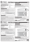
All Mikroelektronika’s development systems feature a large number of peripheral
modules expanding microcontroller’s range of application and making the
process of program testing easier. In addition to these modules, it is also
possible to use numerous additional modules linked to the development system
through the I/O port connectors. Some of these additional modules can operate
as stand-alone devices without being connected to the microcontroller.
Manual
Additional Board
RFid Reader
™
MikroElektronika
RFid Reader
RFid Reader
The RFid Reader additional board is used to read identification cards (RFid Cards) using radio waves.This additional board features
a receiver/transmitter module with antenna and a 2x5 male connector that enables connection with development systems. The
operation of the RFid Reader board is based on amplitude modulation of radio waves and electromagnetic induction. The RFid card
is not provided with the RFid Reader, but you can buy it separately.
2x5 male connector enables the
additional board to be connected
to a microcontroller on the
development system
Antenna provided on the
additional board is used to
receive data stored on the
identification card (RFid Card)
Transceiver EM4095 is used for
AM modulation/demodulation or
as a driver for the antenna
Figure 1: RFid Reader
RFid Reader is powered via a development system it is connected to. The presence of the power supply is indicated by a LED marked
POWER. When the RFid Reader is turned on, a 125kHz voltage is supplied on its antenna. As a result, the anntena starts emitting
an electromagnetic field necessary for reading the RFid identification card. As passive RFid card doesn’t have its own power supply,
it features a coil where the voltage is automatically induced by approaching the card to the RFid Reader’s antenna. This voltage is
necessary for the chip featured on the RFid card to work. The memory chip on the RFid card contains a unique identification code.
This code is sent by the card when it is placed close to the RFid Reader’s anntena. The code is received via this anntena. Then, it is
sent to the microcontroller for further processing.
Figure 2: Identification card (RFid Card)
Figure 3: The principle of RFid Reader’s operation
MikroElektronika
RFid Reader
Figure 4: RFid Reader connection schematic
The function of pins provided on the 2x5 male connector CN1:
OUT
- Output signal from the EM4095 circuit (the code read from the identification card)
RDY/CLK - Clock frequency pin and flag
SHD
- High voltage on this pin causes the RFid Reader to enter sleep mode
MOD
- High voltage on this pin causes signal modulation on the antenna to start
Figure 5: RFid Reader connected to a development system
MikroElektronika