1
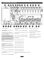
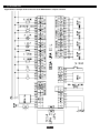
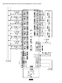
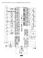
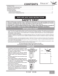
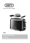
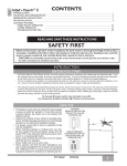
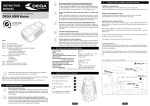
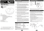
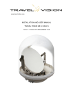
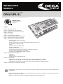
INSTRUCTION
MANUAL
Compact Evaluation Controller
DEGA UPA II L
ISO 9001:2008
Quality Management Systems
Systéme de Qualité
www.sgs.com
Content
Page 2 / For your protection
Page 2 / Technical data and information
Page 3 / Operational and external conditions
Page 3 / Basic types
Page 4 / Accessories
Page 5 / Description of the product
Page 7 / Installation, assembly and disassembly
Page 9 / Operation of the compact controller
Page 9 / Functions of the compact controller
Switching on the compact controller
The idle mode
The gas alarm status (i.e. exceeding the limits of detection levels 1 - 4)
The „PEL“ status of the gas alarm
Failure
Detection of critical temperatures
Detection of flooding
Emergency valve, Solenoid valve
Status of the required service intervention (calibration of sensors)
Functions of the „DEGA UPA II LS“ controller
Functions if the „DEGA UPA II L MULTI“ controller
Page 12 / Operation and maintenance
Operation
Maintenance
Monitoring of the calibration periods
Page 13-15/Appendices
Appendix No. 1: Example of the connection of the compact DEGA UPA II L controller
Appendix No. 2: Example of the connection of the compact DEGA UPA II L S controller
Appendix No. 3: Example of the connection of the compact DEGA UPA II L MULTI controller
Page 16 / General warranty terms and conditions
Reproduction of this manual, or any part thereof, in any form, without the prior written permission of DEGA CZ s.r.o.
is prohibited.
DEGA CZ s.r.o. reserves the right to alter the specifications of the hardware and software described in this manual at
any time and without prior notice.
DEGA CZ s.r.o. bears no liable for any damage resulting from the use of this device!
FOR YOUR PROTECTION
Watch out for static electricity
Prior to installing or handling the product, ensure that you do not have an accumulated static charge. Touch a grounded
metal object to trigger the discharge of any accumulated electric charge. Otherwise the product could suffer damage.
In the event of any failure of the equipment unplug it immediately
If you notice an unusual odour or smoke emanating from the product, unplug it from the mains and from all peripherals.
Continued operation could result in injury or property damage. After disconnecting the product deliver it to an authorised
service centre or the manufacturer for inspection.
Do not use the product in the vicinity of flammable gases or
in areas where there is a potential occurrence of these gases.
Do not use electronic equipment in the vicinity of flammable gases; this could potentially cause a fire or an explosion. The
product is not designed for use in industrial or commercial spaces nor in „Ex“ hazardous areas.
Do not disassemble the product and ensure against its contact with water
Contact with internal components of the product may cause an electric shock. In the case of any failure refer the servicing
of the product exclusively to a certified service centre. Contact with water can create a short circuit in the product and
consequent damage to property or personal injury.
Utilise only certified DEGA accessories
The device is certified and is technically and functionally suitable for authentic „DEGA“ accessories. In the event that the
device is utilised with other products the manufacturer shall not liable for any damages that this may cause.
Use cables of the appropriate types
To ensure compliance with the parameters of the product, to connect the product to other devices or to the power supply
utilise exclusively the cables recommended and described in the Technical Data and Information section.
TECHNICAL DATA AND INFORMATION
Supply voltage: 230V AC/50 Hz
(in the case of the utilisation of the DEGA UPA II 24/12 accessories the supply voltage is 24V DC)
Cable for connecting the DEGA Tc II temperature sensor: the UTP cat 5e (max. length 100 m) or shielded 4x1 mm2 cable
Cable for connecting the DEGA Zc II flood sensor: the UTP cat 5e (max. length 100 m) or shielded 4x1 mm2 cable
Cable for connection of the DEGA TL II external reset button: cable 2x1mm2 (max. length 100m)
Output: 8 x relay (potential-free switching contacts)
RS 485
RS 232
Control of the DEGA HV-DNx emergency valve (in the case of mounting the DEGA UPA II V accessories)
Output of the optical/acoustic signalling:
a) 12V/100mA in the event of a 230VAC supply to the controller
b) 12V/4A in the event of a 24VDC supply to the controller
(in the event of installing the DEGA UPA II 24/12 accessories)
Ingress protection:
IP 20
Relay contact ampacity:
resistance load:
8A / 250 V 50Hz
8A / 30V DC
inductive load: 1,6A / 30V DC
Dimensions (W x H x D):
245 x 72 x 121mm
Weight:0,7kg
PAGE 2
OPERATIONAL AND EXTERNAL CONDITIONS (CSN 33 2000-5-51)
Operating temperature range: - 20°C to +85°C
Relative humidity of the ambient air: max. 95%
Altitude: AC1
The occurrence of humidity:AD1
The incidence of solid foreign bodies: AE1
The occurrence of corrosive or polluting substances:AF1
Vibrations: AH1
The types of materials processed or stored:
BE1
Working environment: BE1 – non-explosive atmosphere
BNV (CSN EN 60079–10)
The compact controller is intended primarily for internal spaces to be mounted in racks or in DEGA boxes.
BASIC TYPES
The DEGA UPA II L – a compact evaluation controller is utilised to supply power for four gas transmitters and for the full evaluation
of the 1-4 level of detection (including the „PEL“ detection). It is designed as a compact device to be mounted on a DIN rail in racks or
in DEGA boxes. The status of all the transmitters is indicated on the controller, including failures, by means of a built-in LCD display
and LED indicators. The controller is fitted with acoustic signalling and a reset button for the acoustic alarm and the function of the
automatic monitoring of the calibration periods.
In conjunction with an external temperature sensor (the DEGA Tc II) it is possible to evaluate up to two levels of critical temperatures.
Flooding can be detected by means of an external flood sensor (DEGA Zc II).
In conjunction with the circuit for controlling the emergency valve (DEGA UPA II V) it is possible, using a current pulse, to close the
emergency valves, e.g. DEGA HV-DNx.
Relays 1-8 have the following functions:
RE8
Switching when exceeding level4 of gas leakage – “LEVEL4”
RE7
Switching when exceeding level3 of gas leakage – “LEVEL3”
RE6
Switching when exceeding level2 of gas leakage – “LEVEL2”
RE5
Switching when exceeding level1 of gas leakage – “LEVEL1”
RE4
The failure relay – “ERROR”
RE3
The relay for acoustic/optical signalling – “ALARM”
RE2
Switching when exceeding level 2 of critical temperature – “TEMP2”
RE1
Switching when exceeding level 1 of critical temperature – “TEMP1”
DEGA UPA II L S – a special version of the compact evaluation controller is utilised to supply power for four gas transmitters and for
a full independent evaluation of 2 levels detection, independently for each of the transmitters. It is designed as a compact device for
mounting on DIN rail in racks or in DEGA boxes. The status of all the transmitters, including failures, is indicated on the controller by
means of a built-in LCD display and LED indicators. The controller is fitted with acoustic signalling and a reset button for the acoustic
alarm and with the function of automatic monitoring of the calibration periods.
Note: This type of controller does not enable the detection of the critical temperature or flooding, nor the control of the emergency
valve.
Relays 1-8 have following functions:
RE8
Switching when exceeding level 2 of gas leakage on channel 4
RE7
Switching when exceeding level 1 of gas leakage on channel 4
RE6
Switching when exceeding level 2 of gas leakage on channel 3
RE5
Switching when exceeding level 1 of gas leakage on channel 3
RE4
Switching when exceeding level 2 of gas leakage on channel 2
RE3
Switching when exceeding level 1 of gas leakage on channel 2
RE2
Switching when exceeding level 2 of gas leakage on channel 1
RE1
Switching when exceeding level 1 of gas leakage on channel 1
PAGE 3
DEGA UPA II L MULTI – the highest version of the compact evaluation controller is utilised to supply power for four gas
transmitters and for a full independent evaluation of detection levels 1-4, independently for each of the transmitters. It is designed
as a compact device for mounting on DIN rail in racks or in DEGA boxes. The status of all the transmitters, including failures, is
indicated on the controller by means of a built-in LCD display and LED indicators. The controller is fitted with acoustic signalling
and a reset button for the acoustic alarm and with the function of automatic monitoring of the calibration periods.
In conjunction with an external temperature sensor (the DEGA Tc II) it is possible to evaluate up to two levels of critical
temperature. In conjunction with an external flood sensor (the DEGA Zc II) flooding can be detected.
In conjunction with the circuit for controlling the emergency valve (DEGA UPA II V) it is possible, using a current pulse, to close the
emergency valves, e.g. DEGA HV-DNx.
Relays 1-8 have the following functions:
RE8
RE7
RE6
RE5
RE4
RE3
RE2
Any function of each relay can be set in accordance with the individual
customer’s requirements - the function of individual relays can be specified to the
manufacturer or set-up using the „DEGA CONFIG“ configuration software.
(i.e. any relay can be set as the alarm for gas detection levels 1-4 from any
transmitter, or for transmitter failure, or for the detection of temperature and/or
of flooding and for optical and acoustic signalling or for any combination thereof ).
RE1
For all the above types of controllers, the following statuses of relay contacts are applicable:
The idle status of all the relays
(with the exception of the “ERROR” relay):
Positions of the
contacts:
Status
C-NC
Idle status
C-NO
Active relay (alarm)
The idle status of the “ERROR” relay:
Positions of the
contacts:
Status
C-NC
Active relay (alarm)
C-NO
Idle status
the system works without any faults
ACCESSORIES
DEGA UPA II BOX –A box with a lock for the installation of the controller outside the rack, i.e. on a wall, etc.
DEGA UPA II UPS - An uninterruptible power supply (30-60 minutes) (in development)
DEGA UPA II 24/12 – Power supply for the controller (24V DC)
DEGA UPA II V – Circuit for control of the emergency valve using a current pulse
(we recommended the DEGA HV-DNx emergency valve)
DEGA Zc II – External flood sensor (cannot be used with version DEGA UPA II L S)
DEGA Tc II – External temperature sensor (cannot be used with version DEGA UPA II L S)
DEGA HV-DNx – Emergency valve can be used in conjunction with DEGA UPA II L V (cannot be used with version DEGA UPA II L S)
External acoustic and optical signalling:
DEGA MR/MY/MG/MSL - Rotating beacon - red/yellow/green/column
DEGA S - Sounder
DEGA TL - External reset button of the acoustic alarm
When using DEGA UPA II L 12/24 accessories it is possible to connect an external acoustic or optical signalling device (12V DC / max.
4 A), i.e. it is possible to use up to 8 x devices connected in parallel, the DEGA MR/MY/MG/MSL and DEGA S) .
PAGE 4
DESCRIPTION OF THE PRODUCT
28
1
2
27
26
3
4
25
24
5
1 – Power supply unit
2 – Dual terminal block for the power
supply (230 VAC)
3 – Terminal block for the external
connection of optical/acoustic signalling
(12V DC, max.100 mA)
Note: When using DEGA UPA II L 12/24
accessories it is possible to connect an
external acoustic or optical signalling
device (12V DC / max. 4 A), i.e. it is possible
to use up to 8 x devices connected in
parallel, the DEGA MR/MY/MG/MSL and
DEGA S) .
4 – Internal acoustic alarm (sounder)
5 – Terminal block for the DEGA Zc II
flood sensor
Note: non-active in the DEGA UPA II L S
version
6 – Terminal block for the DEGA TL reset
button
7 – LEDs of channel 1 (ALARM / ERROR)
8 – Input terminal block for the channel
for transmitter 1
9 – LEDs of channel 2 (ALARM / ERROR)
23
6
7
22
21
8
20
9
19
10
10 – Input terminal block for the channel for
transmitter 2
11 – LEDs of channel 3 (ALARM / ERROR)
12 – Input terminal block for the channel for
transmitter 3
18
11
17
12
16
13
15
14
24 – RS 232 terminal block
25 – RS 485 terminal block
26 – Terminal block for the DEGA Tc II
temperature sensor
13 – LEDs of channel 4 (ALARM / ERROR)
27 – Terminal block for the DEGA HV
emergency valve
14 – Input terminal block for the channel for
transmitter 4
28 – Connector for connecting DEGA
UPA II UPS (in development)
15 – Terminal block for relay 8
16 – Terminal block for relay 7
17 – Terminal block for relay 6
18 – Terminal block for relay 5
19 – Terminal block for relay 4
20 – Terminal block for relay 3
21 – Terminal block for relay 2
22 – Terminal block for relay 1
23 – Jumper for switching communication RS 485/
RS 232
PAGE 5
DESCRIPTION OF THE PANEL
4
5
6
1
2
3
1 – The LED indicator of the serial number of the connected gas detection transmitter
2 – The OPTION button (for switching between the channels (transmitters) displayed
3 – The RESET button for the acoustic alarm
4 – The LCD display
5 – The LED indicator (POWER - ERROR)
6 – The LED indicator for detection (alarm) levels 1 - 4
DESCRIPTION OF THE LCD DISPLAY
1 – Warning concerning the requisite calibration
2 – The channel currently displayed
3 – The type of gas or substance detected
4 – Icon for failure/required service intervention
5 – Icon for the temperature sensor *
6 – Icon for flooding *
7 – The summary gas alarm
8 – Icon for the exceeding of the maximum average concentration - TWA
9 – Units in which the measuring is conducted
10 – Concentration displayed
* This function is active only in the event of connecting an external DEGA-TCIIA temperature sensor / an external DEGA ZcII flood sensor.
PAGE 6
INSTALLATION, ASSEMBLY AND DISASSEMBLY
The compact controller is designed for mounting on a DIN rail in a rack or in the DEGA box. At the customer’s request, it is possible to
supply the LCD display for mounting on the door of the rack.
CAUTION
The controller is supplied with 230VAC voltage (connected to L and N terminals).
When using the DEGA UPA II 24/12 accessories, the controller is supplied with 24VDC voltage (the positive pole is connected to the L terminal
and the negative pole to the N terminal). In the event of connecting this version to a 230VAC power supply, the controller will be destroyed!!!
Four independent gas detection transmitters, the flood sensor and the temperature sensor can be connected to the device:
a) the gas detection transmitter of the DEGA NBx-yL II type is a linear transmitter communicating by means of an analogue
current loop 4-20 mA. It is supplied in versions designed for the detection of natural gas (methane), propane-butane (butane),
carbon monoxide (CO), combustible gases, carbon dioxide (CO2) and more than 100 other gases in accordance with the customer’s
requirements.
b) the gas detection transmitter of the DEGA NSx type with a semiconductor sensor communicating by means of a 4-20 mA current
loop. It only transmits information in regard to two concentration levels.
c) the DEGA NSx-CL, DEGA NSx-EL, DEGA NSx-IL are linear transmitters for use in potentially explosive atmospheres („Ex“ zone 1),
communicating through an analogue 4-20 mA current loop. They are supplied in versions for the detection of natural gas (methane),
propane-butane (butane), carbon monoxide (CO), combustible gases, carbon dioxide (CO2) and more than 100 other gases, in
accordance with the customer’s requirements.
d) the DEGA DV transmitter is a special version of the transmitters (probes) that monitor the concentration of ammonia in water.
Utilised for a 2-level detection.
e) the DEGA Tc II temperature sensor is an external critical temperature sensor with a linear range of 0-99°C.
f ) the DEGA Zc II flood sensor is an external flood sensor for the indication of flooding of the premises (e.g. the boiler room, the
warehouse, etc.)
PAGE 7
CONNECTING TRANSMITTERS TO ALL TYPES OF DEGA UPA II L/S /MULTI CONTROLLERS
Transmitter
Terminal
2
Cable
Terminal
Controller
Ux+
Sx
Ux-
DEGA UPA II L
Shielded 3 x 1 mm2 (max. 600m)
Shielded 3 x 1,5 mm2 (max. 1100m)
1
5
DEGA NBx-yL II
3
4
PE
x = channel number
DEGA NSx-yL II
C+
B+
Shielded 3 x 1 mm2 (max. 600m)
Shielded 3 x 1,5 mm2 (max. 1100m)
Ux+
Sx
S
D-
DEGA UPA II L
UxPE
x = channel number
1
DEGA DV
Shielded 3 x 1 mm2 (max. 600m)
Shielded 3 x 1,5 mm2 (max. 1100m)
Ux+
Sx
2
DEGA UPA II L
UxPE
4
x = channel number
Shielded 4 x 1 mm2 (max. 100m)
UTP cat 5e (max. 100m)
+12V
DEGA Tc II
yellow
green
outB
brown
outA
blue
GND
+
inB
DEGA UPA II L
inA
-
Shielded 4 x 1 mm2 (max. 100m)
UTP cat 5e (max. 100m)
yellow
+12V
DEGA Zc
green
DATA
white/green
GND
PAGE 8
+
DATA
-
DEGA UPA II L
OPERATION OF THE COMPACT CONTROLLER
Two buttons are used for the operation of the compact controller; the
Switching between the channels displayed (transmitters): using the
channels.
button and the
button.
button it is possible to switch between the occupied
Resetting the acoustic alarm: press the
button thereby deactivating the internal piezo-buzzer for 20 minutes; the “ALARM”
relay switches to the idle mode. If, after 20 minutes, the event for which the acoustic alarm was activated still persists, the sounder
starts-up again and the “ALARM” relay is switched on. It is possible shut down the acoustic alarm 3 times in a row and subsequently it
will no longer be active for the duration of the alarm.
Note: Resetting the acoustic alarm causes only temporary deactivation of the acoustic alarm. The other signalling features (relays
LEVEL1, LEVEL2 etc.) remain functional.
Service mode: If it is necessary to replace the transmitter without announcing failure or alarms, it is possible to „freeze“ the status of
all the relays of the compact controller for up to 60 minutes. This is achieved by pressing the
and the
buttons for at least
5 seconds. The display then shows only the length of time up to the reactivation of the compact controller. 60 minutes after entering
the service mode the compact controller switches back to normal. If we wish to manually move out of service mode to normal
operation, we press the
and
buttons again for 5 seconds.
Press the
button in the service mode to test the functions of the compact controller:
- all signalling elements and display will be illuminated (8 seconds)
- the acoustic alarm will be activated (2 seconds)
- sequential switching of all the relays
Changing the setting of the critical temperature: In the event of the requirement for changing the settings of values 1 and 2 of
the critical temperature, in the service mode press the
button for 5 seconds. The level indicating the critical temperature 1 set
will appear on the display. Press
to set the temperature lower, pressing
to set the temperature in the range of 0-99 °C.
Save the temperature set by pressing the
button for 5 seconds. This will lead you to setting level 2 of the critical temperature.
Critical temperature 2 must be set at least one °C higher than critical temperature 1. This adjustment is again carried out using the
and the
buttons. After selecting the correct temperature, save the setting by pressing the
button for 5 seconds
and return to the service mode.
FUNCTIONS OF THE COMPACT CONTROLLER
The description of the relay functions corresponds to the basic model of compact data, the DEGA UPA II L logger.
(in the DEGA UPA II L S and the DEGA UPA II L Multi versions the configuration of the relay is conducted differently and this is
described at the end of this chapter).
SWITCHING ON THE COMPACT CONTROLLER (ON)
After switching on the power supply the LCD display shows the current version of the installed firmware and subsequently all the
indication features are tested. After this sequence, the compact controller counts down the time required for the stabilisation of
the connected transmitters, 20 – 180 s, in accordance with the warm-up time of the individual transmitters. If everything is O.K., the
compact controller goes into normal operation and the „ERROR“ relay is switched to the C4 - NO4 contacts position indicating its
proper operation.
Note: Blocking after switching-on is necessary for the stabilisation of the sensor and for preventing an accidental power outage that could
cause excitation of false alarms!
IDLE MODE (READY)
The compact controller remains in this mode during most of its operation. The information displayed on the LCD display is relative
to the transmitter, the number of which is displayed below the „
“ icon with blue LEDs lit-up next to the displayed channel.
Displaying concentration values from other transmitters or the current temperature from the DEGA Tc II temperature sensor can be
achieved by pressing
.
In the event that the concentration exceeds the maximum level that the connected transmitter is able to detect, the „HI“ symbol
is displayed in place of the values. In the event of concentrations greater than 999, it shows the symbol „t“ indicating multiples of
thousands, e.g. the number 1t1 stands for 1100, or 4t5 stands for 4500 of 99t stands for 99000.
PAGE 9
THE GAS ALARM STATUS (i.e. exceeding levels 1 – 4 of the detection limit)
Should level 1 of concentration be exceeded, the appropriate level of alarm lights up on the LCD display and the LED panel and the
relevant relay will be switched on and the LCD display will show the concentration measured by the transmitter (channel), by which
level 1 of concentration was exceeded. If multiple transmitters exceeded level 1 of concentration, the transmitter with the highest level
of alarm is displayed.
Note 1: Acoustic signalling is activated by default when level 4 of alarm is reached. In accordance with the customer’s requirements, this can
also be set to a lower level.
Note 2: By default, levels of alarm (1 - 4) for individual transmitters are set in accordance with the specifications of the transmitter and they
can be altered in accordance with the customer’s requirements.
Note 3: In the UPA II L - S version the compact controller is equipped only with two-level gas detection and the “ALARM” relay is utilised for
level 1 of alarm on channel 2.
The „PEL“ STATUS OF THE GAS ALARM
(i.e. exceeding the time-weighted average)
When the TWA concentration is exceeded the
icon and
! DANGER !
“LEVEL4” and the “ALARM” relays and the activation of the internal acoustic alarm.
sign are lit up and the switching on of the
PEL (in English TWA- Time-weighted Average)
This function is activated only in the case of the detection of toxic gases (e.g. carbon monoxide (CO), etc.)
Note: Levels of “PEL” alarms for individual gases for specific transmitters are set by default in accordance with the specifications of the
transmitter and can be adjusted in accordance with the customer’s requirements.
Note: This function is not included in the DEGA UPA II L - S version.
FAILURE (ERROR)
In the event of any failure of the compact controller or of its accessories the yellow LED „ERROR“ comes on, the „ERROR“ relay switches
to the C3 - NC3 position, the acoustic alarm is activated, the „ALARM“ relay is switched on (by contacts C4 - NO4) and the appropriate
symbol commences flashing on the display:
- In the event of the failure of the DEGA UPA II L compact controller only a key
symbol flashes on the display.
- In the event of the failure of the gas/liquid transmitter only a key symbol
together with the
together with the number of the channel on which the transmitter that signalled the failure is located.
icon flash on the display,
- In the event of a failure of the critical temperature sensor (DEGA Tc II) only the key
icon flash on the display.
- In the event of the failure of the flood sensor (DEGA Zc II) only the key
symbol and the
symbol and the
icon flash on the display.
Note: In the case of the DEGA UPA II L – S version the “ERROR” relay is not switched on and is used as a level 2 alarm on channel 2.
DETECTION OF CRITICAL TEMPERATURE (only in the event of the DEGA Tc II temperature sensor being connected)
icon and
When exceeding the critical temperature, which is normally set as 45 °C at level 1 and 60 °C at level 2, the
sign are lit up and the contact of the relay associated with a critical temperature level is switched on,
! DANGER !
including the alarm relays for the lower levels. Reaching level 2 of critical temperature leads to the activation of an internal piezobuzzer and the switching on of the „ALARM“ relay.
Note: This function is not included in the DEGA UPA II L – S version.
DETECTION OF FLOODING (only in the event of the flood sensor of the DEGA Zc II being connected)
In the event of the detection of flooding the
“TEMP2” relay contact is switched on.
icon and
! DANGER !
sign lights up on the LCD display and the
Note: In the DEGA UPA II L – S version this function is not included.
Note: If both flooding and a critical temperature are detected, the „TEMP2“ relay is used for detection of both flooding and level 2 of
the alarm of critical temperature.
PAGE 10
EMERGENCY/SOLENOID VALVE
Emergency valve
The circuit for controlling emergency valves is designed to control the solenoid emergency valves with a 12 V DC coil of the
switching power of up to 7 VA. The valve is connected by means of a two-wire cable to the terminals marked „DEGA HV +“ and
„DEGA-HV-“. A voltage pulse is transmitted in the following cases: power failure, failure of the gas transmitters, exceeding level 4 of
concentration.
Note: Connect the emergency valve of the DEGA HV-DN15, DEGA HV-DN20 or DEGA HV-DN25 type to the compact controller.
Solenoid valve
The relay of the compact controller can also be used for controlling the solenoid valves of the “without voltage, closed” type with a
230VAC coil. Connect one wire of the valve coil to the neutral wire. Connect the other wire to the NO terminal of the relay (NO RE8).
Connect the C terminal of relay 8 (C RE8) to the live wire. Valve closure occurs in the following instances: power failure, failure of the
gas transmitter(s), exceeding level 4 of concentration.
Note: The requirement for controlling the solenoid valves must be specified in the order.
THE STATUS OF THE REQUIRED SERVICE INTERVENTION (CALIBRATION OF TRANSMITTERS)
The compact detector, in conjunction with the NBX-II transmitter, is provided with automatic monitoring of the calibration periods
of the gas transmitters.
Following the expiration of 12 months since the last calibration of the transmitters the user is alerted to the necessity of recalibraand the
icon. The compact
tion. This status is displayed by long flashes of „ERROR“ LED, flashing
controller remains in operation.
Following the expiration of 18 months from the most recent calibration of the transmitters, for security reasons the function of the entire compact controller is blocked. This status is displayed as a blinking „ERROR“ LED, a flashing
and the
icon. All the relays are in the C-NO position.
The functions of the compact controller in the special S version
In this version, the compact controller is equipped with only 2-level detection of gases, whereby each transmitter controls 2 separate relays with levels 1 and 2. In this version it is not possible to connect the transmitter of the critical temperature. The „ERROR“ relay
is used for switching on level 2 of alarm on channel 2 and the „ALARM“ relay is used for switching on level 1 of alarm on channel 2.
The internal acoustic alarm remains functional.
All the other features are the same as for the DEGA UPA II L version.
The functions of the compact controller in the special MULTI version
In this version, the settings of the relay switching are fully configurable by means of the DEGA CONFIG configuration software. The
relay configuration options are described in the User Guide for the DEGA CONFIG software.
All the other features are the same as for the DEGA UPA II L version.
PAGE 11
OPERATION AND MAINTENANCE
1. OPERATION
This compact controller does not require any special maintenance during operation. The surface can be cleaned with a cloth as
needed.
2. MAINTENANCE
For proper operation of the detection system (which also includes the controller) it is requisite to periodically undertake specifically
the following servicing of the transmitters connected to the controller:
a) calibration at least once every 6-12 months (i.e. setting the detection limits, checking the responsiveness of the sensor, checking
the system’s functionality). The precise interval is dependent on the level of contamination of the environment, the degree of accuracy
required and the level of occurrence of the selective gases in the environment.
Calibration should be carried out only by authorised service centres holding a valid certificate of competency or by the manufacturer.
b) „Functional checking“ at least once every 3-12 months. Functional checks are performed utilising the test gas at the concentration
that is intended for it – this must not exceed the limit range of the transmitter. We recommend gases with a certified 1st grade of
purity!
Recommendation: For ideal functioning it is recommended to carry out the calibration and the functional checks once every 6
months or the calibration once every 12 months and the functional check once every 3 months.
The means for testing the fire alarm transmitters must not be utilised for these checks!
PAGE 12
APPENDICES
Appendix No.1: Example of the connection of the DEGA UPA II L compact controller
PAGE 13
Blocked
Appendix No.2: Example of the connection of the DEGA UPA II L S compact controller
PAGE 14
Appendix No.3: Example of the connection of the DEGA UPA II L MULTI compact controller
PAGE 15
GENERAL WARRANTY TERMS AND CONDITIONS
When following the instructions for installation, operation and maintenance, the manufacturer guarantee 24 months from
the date of receipt for the product. Should the product purchased be put into operation by an entity other than the seller, the
warranty period commences from the date that the product is put into operation, provided that the buyer ordered its commissioning
within three weeks of its receipt. The customer expressly acknowledges that during the warranty period that extends beyond the
length of the warranty period that is specified in the Commercial Code (the statutory warranty) s/he can neither require replacement
of the product nor may s/he withdraw from the contract.
1. When claiming a product defect it is necessary to submit a proof of purchase that contains the following information: name and
surname, name and business name, address and the warranty card, if the buyer received one from the seller. The validity of the
warranty shall not be affected by non-compliance with the obligations related to the issuance of the warranty card.
2. Claims concerning the product (for a warranty repair only complete devices are accepted) may be filed during the warranty
period only with the seller from which it was purchased; subsequently the seller is required to forward the product to an
authorised service centre or to the manufacturer.
3. A condition for the recognition of the rights under the warranty is the installation of the product having been undertaken by an
authorised person in possession of a valid certificate from the manufacturer.
4. This warranty is not applicable to:
- a product that has not been put into operation by the manufacturer or by a certified employee in possession of a valid
certificate issued by the manufacturer ,
- damage caused by fire, water, static electricity, power surges in the electric supply or in the public network, accident, improper
use of the product, wear and tear
- contamination of the product and its subsequent cleaning,
- damage caused by improper installation, any adjustment, modification or improper manner of use inconsistent with the
instruction manual, the technical standards or the applicable safety regulations in the Czech Republic,
- damage to the product during transportation caused by improper handling or handling of the product in a manner contrary to
the advice provided in the instruction manual,
- DEGA products that have been used in association with other than original DEGA products, including consumables and
accessories,
- bearing additional parts or consumables (e.g. a foil label, seal, etc.), that are detrimental to normal wear and tear during
operation, together with wear and tear of the product and its parts caused by their normal use.
5. Claims regarding a product defect that can be dealt with reasonably quickly and without additional consequences will be
resolved by remedying the defect (repair) or by replacement of the product part , because in such a case it is a contradiction of
the standard norms that the entire product shall be replaced (§ 616, paragraph 4 of the Commercial Code).
6. The buyer who exercises the right of warranty repair is not entitled to the return of the parts that have been replaced.
7. The warranty period can be extended for up to 48 months and its validity can be extended beyond the standard length on the
basis of the conclusion of an individual warranty contract. Further information may be obtained through a specific business
meeting.
8. For the complete version of the general business conditions and of the claims procedure go to www.dega.cz
Manufacturer: DEGA CZ s.r.o., K Žižkovu 640/9, 190 00 Prague 9, Czech Republic
Tax ID: CZ 279 029 43, Company ID: 279 02 943; Telephone (cz) : +420 774 447 660-5, Fax: +420 227 203 512
E-mail: [email protected] , Web: www.dega.cz
© 2012 DEGA CZ S.R.O.
USER MANUAL VER.: 07DEGAUPAIIL201210
PAGE 16