1
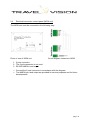
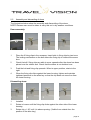
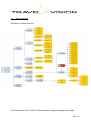
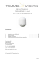
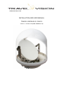
www.travel-vision.com
INSTALLATION AND USER MANUAL
TRAVEL VISION Q6 S / DUO S
Version 1.1 October 2012 (from software 1.1.8)
Foreword
Congratulations on the purchase of your Travel Vision Q6 S / Duo S .
This manual will provide you with all the information you need about the installation,
use and maintenance of the system.
The Travel Vision Q6 S / Duo S ® has been exclusively developed for use on inland
waterways.
The system allows optimal enjoyment of the tremendous variety of radio and TV
programmes currently on offer via geostationary satellites, under way as well as in
port.
The use of high grade materials like stainless steel and durable plastics has been
maximised to ensure a long service life. Maintenance is also minimal, thanks to the
use of stepping motors and toothed belt transmissions.
WARNINGS AND REMARKS
All data is current at the time of going to press. Travelvision BV shall not be liable in
any way for errors made during the drafting of this manual.
Travelvision BV retain the right to introduce any changes deemed necessary due to
product development and to introduce any necessary amendments to the installation,
to this user manual or to the products described in it, without prior notice.
Travel Vision Q6 S / Duo S ® is a registered trademark of Travelvision B.V.
Read this installation and user manual before using your Travel Vision Q6 S / Duo S
® for the first time. Carefully follow the instructions and take note of all warnings
appearing on the equipment and in this user manual.
Installation and must be carried out exclusively by qualified persons.
There are no components within the installation which require service by the user.
Satisfy yourself that the wiring has been correctly connected before taking the
equipment into use.
Switch off and disconnect the power supply before carrying out any maintenance on
the system.
When opening the dome, bear in mind that that the dish antenna can move suddenly
and without warning unless the power supply is disconnected.
The dome must not be cleaned using a high pressure water jet. A soft damp cloth
with soap solution should be used instead.
page
2
In the event that the dome needs to be tilted due to the overall height of the vessel,
consult your dealer for input on cabling, power supply and further measures which
may be required.
For further information we would kindly request that you contact the specialist
supplier where you purchased the system, or contact us directly at:
Travelvision BV
Oude Beeck 4
4251 NP Werkendam
The Netherlands
Tel. +31 (0) 183-505570
Fax + 31 (0) 183-505567
Web: www.travel-vision.com
© Copyright 2012 Travelvision B.V.
page 3
Contents
INSTALLATION AND USER MANUAL
1.1
1.2
2.
2.1
2.2
2.3
2.4
2.5
3.1
3.2
3.3
3.4
3.5
4.1
4.2
4.3.1
4.3.2
4.4
4.5
5.
6.
7.
Travel Vision Q6 S / Duo S ® packaging
Parts checklist
Installation instructions
Installation position identification
Installation of antenna dome and control unit
Electrical connection to antenna dome
Electrical connection of control panel (MCM unit)
Assembly and dismantling of dome
Functions of MCM unit control panel
Operation of MCM unit
Display of status of MCM unit
Display of MCM unit error codes
Explanation of Error Codes
Menu structure
Menu settings
Satellite Selection Travelvision Duo S
Satellite Selection Travelvision Q6 S
Stand-by
Installation Menu
Technical data
IP 55 certificate of protection
Guarantee conditions
…………………………..5
………………………......5
…………………………..6
…………………………..6
…………………………..7
…………………………10
………………………....12
…………………………13
…………………………14
…………………………15
…………………………16
…………………………16
…………………………16
…………………………18
…………………………19
…………………………19
…………………………20
…………………………20
…………………………21
…………………………22
…………………………23
…………………………24
INSTALLATION MANUAL
TRAVEL VISION Q6 S & Duo S
1.
2.
3.
4.
Installation menu MCM unit
Technical data
Warranty conditions
DiSEqC automatic switching between satellites.
…………………………26
…………………………27
…………………………28
…………………………29
page
4
1.1
Travel Vision Q6 S / Duo S ® packaging
The Travel Vision Q6 S / Duo S ® is packed in a strong plastic bag within a
cardboard box measuring 70 x 70 x 90 cm. The equipment can easily be lifted from
the cardboard box by two persons, using the strong plastic bag.
We request that you carry out the following checks before removing the packaging
:
• The cardboard must not be deformed and must not display visible signs of
obvious and serious damage, such as rips in the box or dents caused by
impact.
• The Travelvision tape used to seal the packaging must remain intact.
Note! The Travel Vision Q6 S / Duo S ® is equipped with a special DUO LNB
which is very precisely adjusted. You must ensure that the LNB is not moved
out of position during unpacking.
1.2
Parts checklist
You should find the following components in the packaging:
Antenna dome (antenna unit in lower housing and dome)
Control unit for internal installation (MCM unit)
Manual.
Bag of components:
- 2 no. 5 pole plugs
- 1 no. 2 pole plug
- 3 no. M8 x 45 mm stainless steel bolts
- 3 no. M8 stainless steel lock washers
- 3 no. sealing cap for cable throughput
Note. The bag of components is packaged together with the MCM unit.
page 5
2.
Installation instructions
2.1
Determining installation position
Selection of location for installation of antenna dome
Various factors must be taken into account when selecting the correct installation
location for the antenna dome, these are summarised below:
• The ideal location will have a free line of sight in all directions.
• The antenna dome must be installed at the point where the three axes
intersect (roll, pitch and yaw motion).
• The external unit must be kept away from radar equipment as this can cause
interference; where no other location is possible it is recommended that the
antenna dome be installed a minimum of 1.5 metres below or above the radar
antenna.
• The substrate on which the antenna dome will be installed must be adequately
resilient and vibration free; in case of doubt we recommend that the substrate
should be reinforced with additional constructions.
Rule of thumb for reception of Astra 1 and 3:
An obstacle which is 3 metres away from the dome may be one
metre higher than the dome.
The rule of thumb assumes a minimal elevation of 27 degrees.
page
6
Selection of location for installation of control unit
The following instructions should be followed when selecting the location for the
control unit:
•
•
•
•
2.2
The control unit may be installed in either a visible or a concealed location.
We would however advise that the control unit should be installed in an easily
accessible location because of the potential need to install software updates.
The control unit must not be installed in a damp or inadequately ventilated
space.
Adequate space must be available at the rear of the control unit to allow
cables to be connected.
Installation of antenna dome and control unit
Once the location for the antenna dome has been decided the antenna can be
installed.
For a problem-free installation we recommend that you follow the procedure below:
• Check that the base plate where the antenna dome is to be mounted is level
and vibration free and can support a load of at least 22 kg.
• Before drilling fixing holes, check that there is sufficient room, taking account
of the dimensions of the antenna dome.
• When the ship is in a stable condition the surface should be parallel to the
water surface.
• The following drilling plan must be followed when securing the substructure of
the external unit, with account taken of the point where the cables emerge
from the antenna dome, and the maximal space occupied by the dome:
page 7
Where the Travel Vision Q6 S / Duo S ® cannot be mounted from below using the
M8 bolts and lock washers supplied, it is possible to mount the drive from the inside.
NOTE! Remove the stainless steel screw thread holders from the drive feet with
an M8 bolt and nut before drilling out the holes.
The system can be secured from the inside if sufficiently long M8 stainless steel bolts
are used. With this installation method you will need to ensure that the galvanic
separation, provided by the plastic feet, remains intact.
page
8
Installation of control unit (MCM unit)
Once the location for the installation has been chosen the control unit can be
mounted. The MCM unit may be built in or attached to the mounting clamp provided.
If it is built in the MCM unit can be installed so that it is clamped in place.
If the unit is not appropriately sized for this, the 4 securing holes at the corners of the
front panel can be used for screw attachment.
Dimensions of control unit (MCM unit)
page 9
Electrical connection to antenna dome
The Travel Vision Q6 S / Duo S ® must be connected to a 24 volt DC power supply.
The current drawn when connected to a 24 Volt supply is around 3 amps.
The (brief) switch-on current is appreciably higher and is dependent among other
factors on the supply cable installed.
It is advisable to use a galvanically separated supply.
The supply terminal "+" should be connected to the plug clamp marked "24VDC" and
the "-" terminal to the 0V plug clamp.
The 5-pole plug is to be connected to the MCM unit.
Note:
The system can be switched on and off using a switch which makes and breaks the
supply circuit. This method of switching off will ensure that the system is not
permanently connected to the satellite.
Recommendation:
It is recommended that the system's power supply should be left switched on at all
times. With the system switched on the temperature of the electronics and the
internal climate in the dome is less subject to fluctuation, extending service life. If
necessary the Stand-by button can be used to switch the system off.
•
•
•
•
•
Remove the clamping rings from the cable fairleads and insert the cables
through these.
The cable fairleads which are not used must be sealed off using the sealing
caps provided. If the unused fairleads are not sealed off water may penetrate
the antenna dome, seriously damaging the mechanical structure and the
electronic circuits.
Connect the electrical cables to the appropriate 2 pole and 5 pole plugs and
connect the coax F-connectors. No chemical anti-oxidisation products or
silicone paste must be used with the coax F-connectors, as this can negatively
affect the quality of the radio frequency signal.
Check that the antenna unit can move freely and that there are no points of
friction.
Having completed the installation, cover the antenna lower housing with the
dome.
page 10
The Travel Vision Duo S ® is equipped as standard for the connection of 3 tuners
with unlimited channel reception on Astra 1 (19.2) and simultaneously Astra 3 (23.5).
A fourth tuner can be connected, but with some limitations on reception of Astra 1
(19.2).
Electronics unit
circuit diagram
with 3 tuners
connected,
option switchbox.
The Travel Vision Q6 S ® is equipped as standard for the connection of 4 tuners
with unlimited channel reception. It is possible to connect more tuners with the use of
a switchbox. More information can be provided by your supplier.
Electronics
diagram with 4
receivers and
option more
connected
page 11
2.4
Electrical connection control panel (MCM unit)
The MCM unit must be connected in the following way:
Photo of rear of MCM unit.
Circuit diagram, antenna to MCM
1. 5 pole connector
2. The 2 pole connector is not used
3. RS 232 NMEA in and output
•
•
Connect the 5 pole connector in accordance with the diagram
The NMEA input and output are provided for service purposes and for future
developments
page 12
2.5
Assembly and dismantling of dome
The illustrations below show the assembly and dismantling of the dome.
NOTE! Extreme care must be taken to carry this out in dry weather conditions.
Dome assembly:
1
2
3
4
1
Place the 6 fixing clips in the recesses. Insert bolts in fixing clips by two turns.
The locking mechanism on the bolt allows the fixing clip to rotate at the same
time.
2
Check that all 6 fixing clips are able to move upwards after the dome has been
placed over the rubber seal. Check that the rubber is not doubled over.
3
Push the bolt and fixing clip upwards. When in upper position, rotate to the
right.
4
When the fixing clip clicks against the lower housing, tighten and maintain
rightward pressure on the allen key so that the clip does not come free from
the lower housing.
Dismantling dome:
1
2
3
4
1
Installed
2
Rotate to loosen until the fixing clip clicks against the other side of the lower
housing.
3
Rotate clip +/- 90˚ until it is above opening. (Visible from outside from the
position of the allen key).
page 13
4
Allow the bolt and clip to drop. The fixing is now loosened. It is also possible to
completely loosen the bolt until the clip falls into the lower housing. (6 no.)
3.1
Functions of MCM unit control panel
The MCM unit has 3 functions:
1 Monitoring;
2 Control:
3 Maintenance:
1.
2.
3.
4.
5.
6.
The status of the dish antenna can be seen from the display.
Various error codes can also be displayed.
(see Display of Error Codes and Status)
Remote transmission of commands to the dish antenna
e.g. selection of satellite, stand-by function.
The replacement or updating of software.
Stand-by function (places the system in idle mode)
Down (move down through functions menu)
Up (move up through functions menu)
Enter (select in functions menu)
Escape (move back through functions menu)
USB port (for software updates)
page 14
3.2
Operation of MCM unit
Switching on
The Travel Vision Q6 S / Duo S ® is designed so that putting it into operation is very
straightforward, assuming that the system has been correctly installed.
Switch on your satellite receiver and TV set.
A 24 volt supply will be required when switching on the Travelvision system, and it
must be switched out of stand-by mode if necessary.
N.B. The antenna will start up automatically when the 24V supply is switched on.
The following will then appear on the MCM screen:
System type: (Travelvision Q6 S or Duo S)
This message will disappear after a few seconds, and the system will then begin to
report its status.
Status: satellite (e.g.. Astra 1)
Searching for Limit
This message indicates that the antenna system is in its start-up phase (the system
is searching for its reference points), a process that will take around 1 minute.
On completion of the start-up phase the system will begin its search for the specified
satellite.
After some time the Travel Vision Q6 S / Duo S ® will lock onto the satellite and your
TV set will display the image received.
Status: satellite (e.g. Astra 1)
Tracking
page 15
3.3
Display of status of MCM unit
The display indicates the status of the satellite to be tracked.
All status reports displayed are reports from the dome to the MCM unit.
Status :
3.4
Searching Limit
: The system searches for its reference points
Search/scan for Sat : The system searches for the satellite
Tracking
: The system tracks the satellite
Peaking
: Optimising signal strength
Performing track
: The system positions itself
Stand-by
: The system enters stand-by mode
Display of MCM unit error codes
Various texts will appear on the display to report errors
Error Codes:
E
: Limits not found.
E
: No signal from LNB.
E
: Communication error.
E
: Firmware not found.
E
: Error during .. upgrade
E
: Usb disk not found
E
: No Tuner.
E
: No Tuner set.
E
: Not possible DiSEqC active
E
: Satellite not found
E
: LNB Low Voltage
E
: 22 Khz missing
3.5
Explanation of Error Codes
E
: Limits not found.
The system can not find its reference positions. Reset the system.
If "No Limit" appears again on the display, contact your dealer.
E
: No signal from LNB.
The system is not detecting any signal from the LNB. In this case the LNB may
be defective, or there is a poor connection with one or more of the coax cables
in the system.
E
: Communication error.
There is no communication between the MCM unit and the dome. Check the
wiring between the MCM unit and the dome.
page 16
E
: Firmware not found
No software is installed on the system. Reset the system.
Install software using USB stick.
E
: Error during .. upgrade
The software has not transferred correctly from the USB stick to the antenna
system. Reset the system and repeat the software procedure
E
: USB disk not found
The USB stick has not been found or recognised.
E
: No Tuner.
The tuner circuit is not detected by the motor circuit: contact your dealer.
E
: No Tuner set.
No tuner settings available, repeat software update, check cable and
connections control unit.
E
: Not possible DiSEqC active. (not possible with Travelvision Duo S)
Not possible to select manual other satellite. auto DiSEqC is active. Turn
DiSEqC off in menu Travelvision.(the system those not support auto diseqc
anymore)
E
: Satellite not found
1) Check whether there are any obstructions.
2) Check if the latest Travelvision software has been installed for any possibly
changed satellite frequencies. Consult your dealer
3) You are possibly outside the broadcast area of the desired satellite
E
: LNB low voltage
The LNB into the system has to low voltage, contact your dealer
E
: 22 Khz missing
There is no 22 Khz received at LNB, contact your dealer.
page 17
4.1
Menu structure
Illustration of Menu structure
The Travel Vision Q6 S / DUO S ® menu allows a range of settings to be made.
page 18
4.2
Menu settings
Press the enter key for 2 seconds
Language
Choice of English, Dutch or German
(Press the up and down keys to navigate within the
list. Press the enter key to select).
Info
Information on software version etc.
LCD Illumination
Switch the background lighting on and off
Adjust light intensity
(Press the up and down keys to navigate within the
list. Press the enter key to select)
Restart antenna
The antenna will restart
(Press enter key to restart antenna).
4.3.1 Satellite Selection Travel Vision Duo S ®
Press the up and down keys to navigate within the satellite favourites list.
Press the enter key to select satellite.
N.B! Satellites can be selected for the favourites list via the installer's menu.
Standard settings:
Satellite
Astra 1&3
Astra 2
Hotbird
Position
DiSEqC (not supported by the Travel Vision Duo)
19.2/23,5 E
28.2 E
13 E
Satellites available for inclusion on the favourites list via the favourites list in the
installer's menu:
The Duo Lnb is optimal adjusted for reception Astra 1 & 3, the reception of the other
satellites are possible lower because of these adjustments.
Satellite
Position
Satellite
Position
Astra 1
19,2 E
Sirius
5
E
Astra 3
23,5 E
Thor
1
W
Astra 2
28,2 E
Hotbird
13
E
Eurobird 9a
9
E
Eutelsat W3A
7
E
page 19
4.3.2 Satellite Selection Travel Vision Q6 S ®
Press the up and down keys to navigate within the satellite favourites list.
Press the enter key to select satellite.
N.B! Satellites can be selected for the favourites list via the installer's menu.
Standard settings:
Satellite
Position
Astra 1
19.2 E
Astra 3
23.5 E
Astra 2
28.2 E
Hotbird
13 E
DiSEqC (not supported with switchbox connected)
A
B
C
D
Satellites available for inclusion on the favourites list via the favourites list in the
installer's menu:
Satellite
Position
Satellite
Position
Astra 1
19,2 E
Sirius
5
E
Astra 3
23,5 E
Thor
1
W
Astra 2
28,2 E
Atlanticbird 3
5
W
Hotbird
13
E
Atlanticbird 2
8
W
Hellasat 2
39
E
Atlanticbird 1
12,5 W
Eurobird 9a
9
E
Telstar 12
15
W
Eutelsat W3A
7
E
Hispasat
30
W
Note ! The LNB skew is optimized for reception of the red marked satellites. For
reception of the other satellites the LNB skew needs to be changed, this can only be
done by a certified Travel Vision dealer. Please inform your dealer for further
information.
4.4
Stand-by
Press the on/off key for 2 seconds to place the system in stand-by mode.
page 20
4.5
Installation Menu
Press the enter and escape keys for 5 seconds to select menu
Firmware update
This position is used to update your Travel Vision
antenna with new software
(press the enter key to select)
Insert the USB stick with the latest version of the
software
Press enter: the system will read in the software.
Wait until the antenna is fully re-started before
removing the USB stick! (If this is done prematurely
the antenna will give the error message: "USB disk
not found", and the software must be reinstalled!)
Installer mode
Note! this is provided for installers only, and is
protected with a pin code.
Modifications may have major effects on the
operation of the system.
Tracking settings (correct by default)
System type (input type of Travelvision system)
Satellite in Fav List Satellite settings for favourites list with choice of
DiSEqC settings.
(Press the up and down keys to navigate within the
list. Press the enter key to select).
Having selected "yes" there is the option to modify
the DiSEqC settings (not supported by the Travel
Vision Duo)
page 21
5.
Technical data
Dish diameter
Dome diameter
Dome height
Weight
Packaged volume and weight
approx.
:
:
:
:
:
55 cm.
65 cm.
81 cm.
22.5 kg
lxwxh=69x69x82 cm, Gross weight 30 kg
Power supply
Current drawn
:
:
24..36 V DC
3 Amp. Max.
Cabling
MCM cable
Power cable
Coax cable
:
:
:
4x0.32 mm2 screened
2x1mm2 (minimum)
75 Ohm (H125)
Monitor Output Protocol
Maintenance (Up Load)
:
:
RS422 115200 Bd, N,8,1
RS422 115200 Bd, N,8,1
MCM panel built in dimensions :
MCM panel built-in depth
:
Dimensions of MCM front panel :
136 x 85 mm (l x w)
approx. 40 mm for cabling
150 x 105 mm (l x w)
page 22
6.
Certificate of IP 55 protection
Travelvision BV,
hereby declare that the product Travel Vision Q6 S / Duo S
complies with the Machinery Directive IEC 60529
and is thereby classified as having a degree of protection to IP55.
Werkendam, Netherlands 9 July 2010
C.I. Visser
Product Manager
page 23
7.
Guarantee conditions
1.
The guarantee is valid only where the Travel Vision system has been installed by a person
appropriately authorised/certified installation company (hereinafter referred to as a "dealer").
Our stringent quality control and the demanding requirements imposed on dealers allow
Travelvision b.v. to guarantee the supply of a properly functioning Travel Vision system.
In the event that, despite all these measures, a defect occurs in the Travel Vision system in
normal use within 24 months of installation as a result of faults in manufacture and/or
materials, then this defect will be rectified under the guarantee provisions.
The guarantee should be registered immediately, but must in all cases be submitted to
Travelvision b.v. within 1 month of the installation of the Travel Vision system by the dealer. In
order to provide proof of the registration both for Travelvision b.v. and the owner of the Travel
Vision system the dealer must complete, sign and return the enclosed guarantee certificate.
The guarantee is not transferable.
Travelvision b.v have a help desk which the dealer may contact for free advice relating to the
installation, dismantling and repair of Travel Vision systems.
On first detecting a defect the owner of the Travel Vision system must inform the dealer
immediately and put him in a position where he is able to identify the defect.
Where in the judgement of the dealer a defect can be rectified on site, then the dealer is
authorised to carry out the rectification on site. In the event that this is impossible the dealer
will, without creating any obligation to temporarily install a replacement system, dismantle the
Travel Vision system and take it to his premises for repair, or following consultation with the
help desk, send the system to Travelvision b.v. so that they can carry out the repair.
Travelvision b.v. reserve the right to refer to third parties or to make use of their services in
dealing with the guarantee or offering advice.
The guarantee may only be called upon where all the guarantee conditions have been met.
Liability on the part of Travelvision b.v. is therefore limited to the reimbursement of the costs of
repair or the bearing of such costs by Travelvision b.v., or replacement of the Travel Vision in
whole or in part, or of the component in which the defect has occurred, all entirely according to
the opinion and judgement of Travelvision b.v..
Travelvision b.v. reserve the right to judge, entirely in accordance with their own opinion, that a
defect is attributable to improper use and/or improper installation of the Travel Vision system,
in which event all claims against the guarantee shall lapse and will therefore be rejected.
Travelvision b.v. shall not be responsible for the suitability of the Travel Vision system for any
purpose other than that for which Travelvision b.v. have given undertakings in the Installation
and User Manual. Travelvision b.v. will therefore accept no liability whatsoever for any
damage resulting from such use.
Travelvision b.v. shall not be liable for any defect in the Travel Vision system and/or its
functionality where this is the consequence of damaging external factors, or of the improper or
incomplete functioning of third party products and/or services, or the unavailability thereof.
Travelvision b.v. will therefore accept no liability whatsoever for any damage resulting from
such use.
2.
3.
4.
5.
6.
7.
8.
9.
10.
11.
12.
13.
page 24
INSTALLATION MANUAL
TRAVEL VISION Q6 S & Duo S
Version 1.1 October 2012 since software version 1.1.8
Contents
1.
2.
3.
4.
Installation menu MCM unit
Technical data
Warranty conditions
DiSEqC automatic switching between satellites.
…………………………26
…………………………27
…………………………28
…………………………29
Travelvision BV
Oude Beeck 4
4251 NP Werkendam
The Netherlands
Tel. +31 (0) 183-505570
Fax + 31 (0) 183-505567
Web: www.travel-vision.com
© Copyright 2012 Travelvision b.v.
page 25
1.
Installation menu MCM unit
Press enter and escape key for 5 seconds
Firmware update:
This position is used to update the Travel Vision antenna with new software
(press the enter key to select)
Insert the USB stick with the latest version of the software
Press enter: the system will read in the software.
Wait until the antenna is fully re-started before removing the USB stick! (If this is
done prematurely the antenna will give the error message: "USB disk not found", and
the software must be reinstalled!)
Install. Mode (installateurs mode)
Note! this is provided for installers only, and is protected with pin code 22.
(Press up and down and enter for selection)
Changes have great influence on operation !
Tracking settings:
Standard settings to be used , changes only in consultation with Travelvision
BV.
System type:
Select type Travelvision for right operation software electronics:
1.
2.
3.
4.
5.
Travelvision Modi S
Travelvision S
Travelvision Q6 S
Travelvision Duo S
Unknown (with startup, electronics keeps asking what type of antenna )
(Press up and down and enter for selection)
page 26
4.3.1 Satellite Selection Travel Vision Duo S ®
Select satellites to be displayed in favourites list, also DiSEqC changes.
Press the up and down keys to navigate within the satellite favourites list.
Press the enter key to select satellite.
Standard settings:
Satellite
Astra 1&3
Astra 2
Hotbird
Position
DiSEqC (not supported by the Travel Vision Duo S)
19.2/23,5 E
28.2 E
13 E
Favourites list:
Satellites available for inclusion on the favourites list via the favourites list in the
installer's menu:
The Duo Lnb is optimal adjusted for reception Astra 1 & 3, the reception of the other
satellites are possible lower because of these adjustments.
We strongly recommend not to turn or adjust the Duo LNB!
Satellite
Position
Satellite
Position
Astra 1
19,2 E
Sirius
5
E
Astra 3
23,5 E
Thor
1
W
Astra 2
28,2 E
Hotbird
13
E
Eurobird 9a
9
E
Eutelsat W3A
7
E
page 27
4.3.2 Satellite Selection Travel Vision Q6 S ®
Select satellites to be displayed in favourites list, also DiSEqC changes.
Press the up and down keys to navigate within the satellite favourites list.
Press the enter key to select satellite.
Standard settings:
Satellite
Astra 1
Astra 3
Astra 2
Hotbird
Position
19.2 E
23.5 E
28.2 E
13 E
DiSEqC (not supported with switchbox)
A
B
C
D
Satellites available for inclusion on the favourites list
Note ! For reception of some satellites the LNB skew needs to be changed, this
can only be done with use from a spectrum analyzer!
Satellite list
Satelliet
Positie
Satelliet
Positie
Astra 1
19,2 E
Sirius
5
E
Astra 3
23,5 E
Thor
1
W
Astra 2
28,2 E
Atlanticbird 3
5
W
Hotbird
13
E
Atlanticbird 2
8
W
Hellasat 2
39
E
Atlanticbird 1
12,5 W
Eurobird 9a
9
E
Telstar 12
15
W
Eutelsat W3A
7
E
Hispasat
30
W
The LNB is standard adjusted with a average cross polarization to receive the red
marked satellites for common traveling area.
With all other satellites, probably the LNB skew needs to be adjust.
Adjustments should be made for satellite wish and traveling area of costumer.
The rule of thumb assumes the crosspol may deviate max.10 degrees.
It could also be the LNB is adjusted to 1 and only 1 working satellite.
When traveling area is different as standard adjust area (Rotterdam-Basel), we
recommend to adjust the lnb skew to costumers travelling area.
Useful Tool: www.dishpointer.com
Note:
Please consult the opportunities with advantages and disadvantages with
costumer.
page 28
4. DiSEqC automatic switching between satellites. Only with Q6 S!
Standard option within software Q6S:
The Q6 S electronics uses DiSEqC controle to auto switch between satellites.
Connect the costumers receiver directly to the electronics of the Q6 S.
Be sure to set the DiSEqC settings from connected receiver the same as
DiSEqC settings in Travelvision Q6 S.
DiSEqC choices in Travelvision Q6 S:
DiSEqC: Yes
LNB A
LNB B
LNB C
LNB D
No
Note ! Diseqc is not supported when using a switchbox
You can select it, but the antenna does not response
page 29