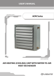
1
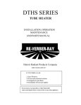
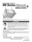
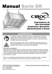
Premium User Interface
Installation, Operation,
Maintenance Manual
Energy Saving Modulating Plus Controller
for Re-Verber-Ray® Brand MP Series Heaters
Keep these instructions for future reference.
!
WARNING
Failure to read and follow all
instructions carefully before
installing or operating this control
could cause personal injury and/
or property damage.
!
CAUTION
Electrical Shock Hazard.
To prevent electrical shock and/
or equipment damage,
disconnect electric power to the
system at the main fuse or circuit breaker box
until installation is complete.
© 2012 Detroit Radiant Products Co.
21400 Hoover Road • Warren, MI 48089
Phone: (586) 756-0950 Fax: (586) 756-2626
www.detroitradiant.com • [email protected]
LIOPUI-Rev. 29112
Print: 1M-10/12_r1-6/13(CDS)
TH-PUI Series
Table of Contents
1.0 Introduction and Overview . . . . . . . . . . . . . . . . . . . . . . . . . . . . . . . . . . . . . . . . . . . . . . . . . 3
Specifications . . . . . . . . . . . . . . . . . . . . . . . . . . . . . . . . . . . . . . . . . . . . . . . . . . . . . . . 3
Quick Reference . . . . . . . . . . . . . . . . . . . . . . . . . . . . . . . . . . . . . . . . . . . . . . . . . . . . . 4
2.0 Installation . . . . . . . . . . . . . . . . . . . . . . . . . . . . . . . . . . . . . . . . . . . . . . . . . . . . . . . . . . . . . . 5
Wiring Connections . . . . . . . . . . . . . . . . . . . . . . . . . . . . . . . . . . . . . . . . . . . . . . . . . . 6
Installer Configuration . . . . . . . . . . . . . . . . . . . . . . . . . . . . . . . . . . . . . . . . . . . . . . . . . 7
Main Menu . . . . . . . . . . . . . . . . . . . . . . . . . . . . . . . . . . . . . . . . . . . . . . . . . . . . . . . . . 7
Service Mode Menu . . . . . . . . . . . . . . . . . . . . . . . . . . . . . . . . . . . . . . . . . . . . . . . . . . 7
Commissioning Menu . . . . . . . . . . . . . . . . . . . . . . . . . . . . . . . . . . . . . . . . . . . . . . . . . 8
Mode Map . . . . . . . . . . . . . . . . . . . . . . . . . . . . . . . . . . . . . . . . . . . . . . . . . . . . . . . . . 9
3.0 Programming . . . . . . . . . . . . . . . . . . . . . . . . . . . . . . . . . . . . . . . . . . . . . . . . . . . . . . . . . . . 10
Manual Operation for Non-programmable Mode . . . . . . . . . . . . . . . . . . . . . . . . . . . 11
Blast Mode . . . . . . . . . . . . . . . . . . . . . . . . . . . . . . . . . . . . . . . . . . . . . . . . . . . . . . . . 11
Mode Selection Guide . . . . . . . . . . . . . . . . . . . . . . . . . . . . . . . . . . . . . . . . . . . . . . . . 12
Connecting to a BMS System . . . . . . . . . . . . . . . . . . . . . . . . . . . . . . . . . . . . . . . . . . 13
4.0 Troubleshooting and Service . . . . . . . . . . . . . . . . . . . . . . . . . . . . . . . . . . . . . . . . . . . . . . 15
5.0Limited Warranty . . . . . . . . . . . . . . . . . . . . . . . . . . . . . . . . . . . . . . . . . . . . . . . . . . . . . . . . 16
6.0Mounting Pattern . . . . . . . . . . . . . . . . . . . . . . . . . . . . . . . . . . . . . . . . . . . . . . . . . . . . . . . . 16
2
TH-PUI Series
1.0 Introduction and Overview
The Premium User Interface is a smart logic controller that offers the optimal performance out of the MP
Series heater. It modulates the heater(s) with a full PID controller considering various inputs and outputs.
It utilizes the current set temperature, room temperature, mode selected, and other items to set the speed
of modulation. Therefore, the heater output optimally matches the heat loss of the space.
Specifications
Physical Dimensions:
Height: 7-3/4 Inches
Width: 3-5/8 Inches
Depth: 1-7/8 Inches
Programming Choices:
Non-programmable
7-Day programmable
Temperature Range:
35°F – 120°F
Differential:
1.0°F
Electrical Rating:
Connection Type – RS485
Constant Power – 15VDC (from heater)
Battery – 3VDC (CR2032s)
Maximum Operating Humidity Level:
85% Non-Condensing
Additional Features:
Optional remote temperature sensor
Optional outdoor air sensor
Positive off
BMS compatibility
4-20mA
0-10VDC
3
TH-PUI Series
Quick Reference
Figure 1.1 • TH-PUI Controller Features
Front View
Base
Mounting
Holes
#1 Phillips
screw
(6 provided)
Digital
Screen
Display
Contrast
Adjust
BMS
Jumper
Blast
Mode Key
Power Key
Battery
Mode/Set
Key
Down Arrow
Key
Wire
Terminal
Block
Up Arrow Key
Ribbon
Connector
Thermostat
Wire Hole
Mounting
Holes
Figure 1.2 • TH-PUI Controller Home Screen Readout Description
Operation Mode
(Indicates the operation
that is currently selected)
Set Temperature
(Indicates the desired
temperature)
Date
(Indicates the
present date)
Time and Room
Temperature
(Alternates between the time
of day and the actual room
temperature)
4
TH-PUI Series
2.0 Installation
!
WARNING
Electrical Shock Hazard
Disconnect power at the main fuse or breaker prior to installing this unit.
Installation
1 Using the template on page 16, mark hole locations for mounting and wire inlets.
2 Drill mounting holes. Ensure that the wires will feed through the wire opening in the base of the thermostat.
3 Remove cover from the base by unscrewing the two (2) #1 Phillips screws from the base. Carefully disconnect
ribbon connector from the base by pulling it straight off of the board.
!
CAUTION
Forcing or straining the ribbon cable will cause damage to the unit.
4 Fasten base snugly to the wall or mounting surface utilizing the mounting holes provided. Level as necessary
for visual purposes (unit being out of level will not affect performance).
5 Route 18 ga. shielded thermostat wire through the hole provided in the back of the base.
6 Connect wires to the terminal block following the appropriate wiring diagram.
7 Carefully re-connect the ribbon connector to the base and set the cover in place. Secure with the six (6)
screws provided.
5
TH-PUI Series
Wiring Connections
Chart 2.1 • Terminal Wiring Designations
Terminal Designation
Description
R (15+)
Constant power 15VDC from heater
W (485-)
RS485 communication wire, negative inverting pin
B (485+)
RS485 communication wire, positive non-inverting pin
G (GND)
Ground, reference for RS485, connection point for shield drain wire
COM
Common wire from 4-20mA or 0-10V signal (OPTIONAL)
4-20mA
4-20mA signal from BMS system (OPTIONAL)
0-10VDC
0-10VDC signal form BMS system (OPTIONAL)
0-20VDC
0-20VDC signal controller (OPTIONAL)
Room Thermistor
Connector for remote temperature sensor, 10kΩ (OPTIONAL)
Room Thermistor
Connector for remote temperature sensor, 10kΩ (OPTIONAL)
Outdoor Thermistor
Connector for outdoor temperature sensor, 10kΩ (OPTIONAL)
Outdoor Thermistor
Connector for outdoor temperature sensor, 10kΩ (OPTIONAL)
GENERAL WIRING DIAGRAM
Figure 2.1 • General Wiring Diagram
BR
ROOM
THERMISTOR
BR
BR
G
W
R
CONN C
TSTAT (R)
TSTAT (W)
PROBE
PROBE
PWM (+)
PWM (-)
[To Valve]
R
CONN B
SLAVE HEATER
CONN C
TSTAT (R)
TSTAT (W)
PROBE
PROBE
PWM (+)
PWM (-)
[To Valve]
(+)
UI
CONNECTOR A
PRESSURE SENSOR
[HIGH]
[LOW]
0-10/20V
4-20mA
COM
Chasis
GND
485(+)
485(-)
15V
M/S
Detroit Radiant P/N TP-3250
EPN: EC-029-001
IGNITION
SIGNAL
DIP SWITCHES
UNDER COVER
open
N.O. (RELAY)
COM (RELAY)
VALVE SIGNAL
BLOWER
NEUTRAL
FUSE - 3A [Under Cover]
SERVICE
MODULATION
FAN
T-STAT
POWER
MODEL SELECT
[Power In]
On/Off
On/Off
5v (+)
Signal
GND
24VAC
open
COM
DIP SWITCHES
UNDER COVER
R
UI
CONNECTOR A
CONN B
(+)
0-10/20V
4-20mA
COM
Chasis
GND
485(+)
485(-)
15V
M/S
Detroit Radiant P/N TP-3250
EPN: EC-029-001
IGNITION
SIGNAL
FUSE - 3A [Under Cover]
SERVICE
MODULATION
FAN
T-STAT
POWER
MODEL SELECT
[Power In]
PRESSURE SENSOR
[HIGH]
[LOW]
Y
BR
On/Off
On/Off
5v (+)
Signal
GND
O
24VAC
open
COM
BK
BL
BR
open
N.O. (RELAY)
COM (RELAY)
VALVE SIGNAL
BLOWER
NEUTRAL
ROOM
THERMISTOR
OUTDOOR
THERMISTOR
COM
4-20mA
0-10V
+15V
485(-)
485(+)
GND
OUTDOOR
AIR SENSOR
MASTER HEATER
6
TH-PUI Series
Installer Configuration
To enter the menu, press
Mode/Set. This displays the main menu of the controller. Press
down arrow to cycle through the menu items. Press
through the adjustment options with the
up arrow or
Mode/Set to adjust the selected menu item. Cycle
down arrow keys. Press
selected value. To return to the home screen, press the
up arrow or
Mode/Set to enter the
power key. Menus will auto exit after a
predetermined time if no action is taken.
Main Menu
1 Set the Desired Temperature: When the programmed schedule is turned off, this feature will allow the user
to select the desired temperature. If the unit is set to operate within the scheduled program, the set point
temperature is bypassed.
2 Select Mode: This feature allows the user or installer to select the desired operating mode of the heater(s).
There are three modes to choose from: Economy, Standard, or Comfort. For more information on the modes,
see pages 8 & 9 or refer to the MP Series Insert Manual (LIOMP).
3 Run Program: This controller has the ability to run on a 7-day programmable schedule or operate as a
non-programmable thermostat. In this menu, user can turn the program on or off, or enter the sub-menu to
adjust the program schedule.
4 Set Date: Adjust the date to the current calendar date.
5 Set Time: Adjust the time to the current time of day.
6 Service Mode: This menu will allow the installer to enter into a sub-menu of configurations that is not
normally accessed by the user. To enter this menu, press the
Mode/Set key twice.
7 Exit: Select this menu item to exit to the previous menu, or simply press the
power key to return to the
home screen.
Service Mode Menu
1 Set Temperature Sensor: This allows user to select the method of sensing the temperature.
The options are Local, Heater, and Remote.
A.Local: Utilizes the built in thermistor on the Premium User Interface.
B.Remote: Utilizes a remote thermistor connected to the Premium User Interface.
C.Heater: Utilizes a thermistor connected to the modulating controller on the heater.
2 Outdoor Sensor: The installer can specify if an outdoor air temperature sensor is attached. This allows
additional features to be activated on the Premium User Interface. For more information, reference the MP
Series Insert Manual (LIOMP).
3 High Temperature Lockout: This feature allows user to turn on or off the ability to keep the heater from
coming on if the outdoor temperature is higher than the desired temperature.
4 Set Temperature Lockout: User can adjust the set point temperature for the high temperature lockout.
The factory default is 100°F.
5 Set °F / °C Display: Select the desired temperature unit of measure. Factory default is °F.
7
TH-PUI Series
6 Format Time: Select the desired time format from 12hr to 24hr. Factory default is 12hr.
7 Daylight Savings: Select if the unit is to automatically correct for daylight savings. Factory default is off.
8 Backlight Format: This feature allows user to have the backlight on continuously or just on with the touch of
a key. In low light conditions, the continuous backlight improves contrast.
9 Software Version: This will display the software version of the Premium User Interface.
10 Lifetime Statistics: This will allow the user to view some key statistics of the heater, such as the number of
cycles, total runtime hours, total heating hours, and number of faults. For troubleshooting purposes, user can
reset the statistics if needed.
11 Building Management System (BMS): The Premium User Interface can be connected to most building
management systems. This menu item allows the installer to select the type of BMS employed. In addition,
the jumper on the base must also be set to the proper type (4-20mA or 0-10VDC). For more information, see
Building Management Systems on page 13 of this manual.
12 Commissioning: This feature allows the installer to enter another sub-menu where they can select certain
tools for troubleshooting or commissioning. The code to enter this menu is a three (3) character code:
A.Press in sequence:
Mode/Set,
up arrow,
down arrow.
13 Reset Control: This feature allows the controller to be reset to the factory default settings.
14 Exit Service: This will allow user to exit back to the main menu.
Commissioning Menu
1 Model of Heater: This will display the model of the Master heater as well as the heater’s software version.
2 Test Firing Rate: To assist in measuring a stable manifold pressure this feature allows the unit to be
temporarily locked into a test firing rate of 100% or 1%. Please reference the MP Series Insert Manual
(LIOMP) for proper manifold pressures.
3 Pressure Differential: This feature allows the technician or installer to read the pressure differential of the
master heater as it is running. This is measured by the pressure transducer of the modulating controller.
4 % Open Gas Valve: This feature allows the technician or installer to read the heaters % open of the gas
valve as determined by the modulating controller. This is for reference only, and does not necessarily indicate
proper operation of the heater.
5 Exit: This feature will return user to the previous menu, the Service Mode Menu.
8
TH-PUI Series
Mode Map
SERVICE MODE
(Auto exit after 5 min.)
SET TEMP SENSOR
LOCAL
REMOTE
HEATER
Home Screen
OUTDOOR SENSOR
NOT INSTALLED
INSTALLED
HIGH TEMP LOCK
ON
MAIN MENU
(Auto exit after 20 sec.)
OFF
SET TEMPERATURE
SET TEMP LOCKOUT
70°F
100°F
SELECT MODE
SET °F/°C DISPLAY
ECONOMY
°F
STANDARD
°C
COMFORT
FORMAT TIME
RUN PROGRAM
12 Hr
ON
PROGRAM MENU
(Auto exit after 5 min.)
MONDAY
OCCUPIED 70°F
UNOCCUPIED 62°F
TUESDAY
OCCUPIED 70°F
UNOCCUPIED 62°F
WEDNESDAY
OCCUPIED 70°F
UNOCCUPIED 62°F
24 Hr
OFF
DAYLIGHT SAVINGS
ADJUST SCHEDULE
AUTO ADJUST
EXIT
OFF
SET DATE
BACKLIGHT FORMAT
DD-MMM-YY
ON WITH TOUCH
SET TIME
ALWAYS ON
12:00A
SOFTWARE VERSION
SERVICE MODE
VERSION X.X
ENTER SERVICE
LIFETIME STATS
EXIT
CYCLES: XXXXXX
EXIT
HOURS: XXXXXX
FAULTS: XXXXXX
THURSDAY
RESET STATISTICS
OCCUPIED 70°F
UNOCCUPIED 62°F
FRIDAY
OCCUPIED 70°F
UNOCCUPIED 62°F
SATURDAY
OCCUPIED 70°F
UNOCCUPIED 62°F
SUNDAY
OCCUPIED 70°F
UNOCCUPIED 62°F
TIMING ADJUST
EXIT
STATE OF CONTROL
TIMING ADJUST
(Auto exit after 20 sec.)
(STATES OR ERRORS)
WEEKDAYS
BLDG MGMT SYSTEM
COMMISSIONING
(Auto exit after 30 min.)
MODEL OF HEATER
MP-115N V 8.0
OCCUPIED 06:00A
4-20mA
UNOCCUPIED 05:00P
0-10VDC
OFF
OFF
100% (BLAST)
SATURDAY
OCCUPIED 08:00A
COMMISSIONING
UNOCCUPIED 05:00P
CODE ACCESS ONLY
SUNDAY
RESET CONTROL
TEST FIRING RATE
1% (MINIMUM)
PRESSURE DIFF
0.200
OCCUPIED 08:00A
RESET TO DEFAULT
% Open Gas Valve
UNOCCUPIED 05:00P
EXIT
35
EXIT
EXIT
9
EXIT
TH-PUI Series
3.0 Programming
Programming
Prior to adjusting the program schedule, verify that the date and time are properly set. The program will run on a
7 day schedule. The controller will offer two set points for each day of the week. One for occupied, and one for
unoccupied. The times and temperatures of these are adjustable to the users needs to reach their comfortable
temperature.
Chart 3.1 • Factory Pre-Set Programming
Occupied
Day of the
Week
Unoccupied
Temperature
Time
Temperature
Time
Monday
6:00A
70°F
5:00P
62°F
Tuesday
6:00A
70°F
5:00P
62°F
Wednesday
6:00A
70°F
5:00P
62°F
Thursday
6:00A
70°F
5:00P
62°F
Friday
6:00A
70°F
5:00P
62°F
Saturday
6:00A
70°F
5:00P
62°F
Sunday
6:00A
70°F
5:00P
62°F
To Adjust the Program:
1 Press the
2 Press the
3 Press the
4 Press the
5 Press the
Mode/Set key to bring up the main menu.
down arrow key twice (2X) until the screen called ‘Run Program’ is displayed.
Mode/Set key to activate the selection field.
down arrow key until the selection ‘Adjust schedule’ is flashing, then press
up arrow or
Mode/Set.
down arrow key to cycle through the days of the week and the occupied and
unoccupied desired temperature.
6 To adjust the desired temperature, press the
Using the
up arrow or
Mode/Set key to initiate the temperature to start flashing.
down arrow, adjust the temperature to the desired set point.
7 Repeat steps 5-6 until all of the program temperatures are set to the desired set point.
8 To set the time schedule for the occupied and unoccupied times, select ‘Timing adjust’ from the menu and
press
Mode/Set.
9 Select the desired timing to adjust and press the
down arrow to adjust the hours. Press
Mode/Set key. Press the
up arrow or
Mode/Set again to adjust the minutes. Press
Mode/Set
to lock in the adjusted timing.
10 Once all timings have been selected, press
power key or select Exit to return to the home screen.
10
TH-PUI Series
Chart 3.2 • Worksheet for Re-Programming the 7-Day Program
Occupied
Day of the
Week
Time
Temperature
Time
Unoccupied
Temperature
Monday
Tuesday
Wednesday
Thursday
Friday
Saturday
Sunday
Manual Operation for Non-programmable Mode
The TH-PUI controller has the ability to run like a standard non-programmable thermostat. To activate this ability,
the ‘run program’ must be off. To verify this, from the home screen, press the
Mode/Set key, then the
down arrow key twice. The header will display ‘RUN PROGRAM’. The bottom line should read ‘OFF’. If it does
not, press the
Mode/Set key until the bottom line is flashing and then select off with the
up arrow or
down arrow key.
1 Press
Mode/Set key to bring up the main menu.
2 Press the
down arrow key twice until the screen called ‘Run Program’ is displayed.
3 Press the
Mode/Set key to activate the selection field.
4 Press the
down arrow key until the selection ‘Adjust schedule’ is flashing, then press
Mode/Set.
BLAST Mode
The BLAST Mode allows users to temporarily override the preset program or temperature setting by turning on
the heater(s) to 100% input rate and not allowing it to modulate. This feature would be used to compensate for
rapid changes in the environment, such as a loading door open, a cold mass introduced into the environment, or
other high demand situations. This is a temporary, timed option that is selected by the user on demand.
When the
Blast key is pressed, it will initiate the blast mode. The desired timer for the mode can then be
selected by pressing the
up arrow or
down arrows. The timing is set in 10 minute increments, with a
maximum time of 50 minutes. During the sequence, the operation mode indicator will read BLAST, and the
remaining time will be read in the date indicator area. Once the timer has expired, the unit will revert back to the
normally scheduled program.
11
TH-PUI Series
Figure 3.1 ● Blast Mode Display
Blast Selection
Blast Operation
If BLAST enabled:
Display L1: BLAST replaces MODE
Display L2: BLAST minutes replace DATE
During BLAST operation:
L2: Countdown minutes remaining
(colon flashes to indicate timer active)
Blast mode can never be locked on indefinitely. If the heater is transitioning from BLAST mode to the normally
scheduled program, the heater may not shut off if the program is not satisfied. However, it will revert back to the
ability to fully modulate. To discontinue Blast Mode, press
down arrow until no time remains.
Mode Selection Guide
The MP Series heater is programmed to operate on several different performance curves, or ‘MODES’. These
curves are to allow the user to select their desired operation that best accommodates their specific need. The
performance curves can be selected by the Premium User Interface (TH-PUI) under the main menu.
The three available modes are:
Economy Mode: Unit operates to maximize thermal efficiency.
Comfort Mode: Unit operates to maximize perceived human comfort.
Standard Mode: Unit operates as a balance between comfort and economy mode.
These modes can be selected at any time during normal cycles of the heater. The currently selected mode will be
displayed in the upper left hand corner of the home screen. Factory default is ‘Comfort Mode’.
Chart 3.3 • Mode Selection and Application Chart
Comfort Mode
Standard Mode
Economy Mode
•Patios
•Loading docks
•Break areas and lunch rooms
•Kennels
•Parts counters and service desks
•Golf driving ranges
•Woodworking shops
•Service garages
•Fire stations
•Populated warehouse heating
•Manufacturing
•Auto showrooms
•Aircraft hangars
•Car washes
•Pole barns
•Foundries
•Unpopulated warehouses
For more information about the modes and their performance curves, please see the MP Series Insert Manual
(LIOMP).
12
TH-PUI Series
To Select the Desired Mode:
1 Press the
Mode/Set key to bring up the main menu.
2 Press the
down arrow key twice until the ‘Select Mode’ screen is displayed.
3 Press the
Mode/Set key to activate the selection field.
4 Press the
up arrow key or
5 Press the
Mode/Set key to lock in the selection.
6 Press the
power key to exit and return to the home screen.
down arrow key to select the desired mode.
Connecting to a BMS System
The Premium User Interface allows a building management system or remote analog signal to be used to dictate
the firing rate of the MP Series. Most building management systems output a PID loop control for this purpose.
The Premium User Interface can receive a 4-20mA signal, 0-10VDC signal, or 0-20VDC signal. The input rate of
the heater is varied linearly according to the percentage of the signal. If a positive off is desired, the control signal
can be wired in series through another set of contacts on the BMS controller.
Configuring the Premium User Interface for a BMS System
1Ensure the proper wire connections are made per the selected system’s signal (see wiring diagram).
2Configure the BMS Jumper located in the upper right corner of the base to the proper position for the system’s
signal (see figure 2.2).
3Under the Service mode Menu (See page 7, Service Mode), select ‘BLDG MGMT SYSTEM’. Press
Mode/Set key.
4Press
up arrow or
down arrow key to select the appropriate signal being connected.
5Press the
Mode/Set key again to lock in the selection.
6Press the
power key to return back to the home screen.
NOTE: The Building Management System (BMS) option under the Service Access Menu must be turned on to
the correct configuration in order for the heater to operate according to the signal. If it is ‘OFF’ then the heater will
revert back to the normal operation of the schedule built into the Premium User Interface.
Figure 3.2 • BMS Jumper Configurations
No Jumper
Place
Jumper
Here
13
[To Valve]
DIP SWITCHES
UNDER COVER
CONN C
MODEL SELECT
R
M/S
CONNECTOR A
CONN B
Detroit Radiant P/N TP-3250
EPN: EC-029-001
UI
G
[To Valve]
MODEL SELECT
BL
W
R
CONN C
BR
BR
[Power In]
FUSE - 3A [Under Cover]
DIP SWITCHES
UNDER COVER
MODEL SELECT
CONN C
R
IGNITION
SIGNAL
DIP SWITCHES
UNDER COVER
CONNECTOR A
CONN B
BL
BR
M/S
CONN B
Detroit Radiant P/N TP-3250
EPN: EC-029-001
UI
Detroit Radiant P/N TP-3250
EPN: EC-029-001
CONNECTOR A
UI
PRESSURE SENSOR
[HIGH]
[LOW]
(+)
0-10/20V
4-20mA
COM
Chasis
GND
485(+)
485(-)
15V
M/S
open
N.O. (RELAY)
COM (RELAY)
VALVE SIGNAL
BLOWER
NEUTRAL
FUSE - 3A [Under Cover]
SERVICE
MODULATION
FAN
T-STAT
POWER
BR
(+)
W
BL
PRESSURE SENSOR
[HIGH]
[LOW]
BR
On/Off
On/Off
5v (+)
Signal
GND
[Power In]
IGNITION
SIGNAL
O
+15V
485(-)
485(+)
ROOM
THERMISTOR
OUTDOOR
THERMISTOR
COM
4-20mA
0-10V
GND
BR
open
N.O. (RELAY)
COM (RELAY)
VALVE SIGNAL
BLOWER
NEUTRAL
[To Valve]
W
0-10/20V
4-20mA
COM
Chasis
GND
485(+)
485(-)
15V
O
BL
SERVICE
MODULATION
FAN
T-STAT
POWER
24VAC
open
COM
G
TSTAT (R)
TSTAT (W)
PROBE
PROBE
PWM (+)
PWM (-)
BR
On/Off
On/Off
5v (+)
Signal
GND
24VAC
open
COM
W
TSTAT (R)
TSTAT (W)
PROBE
PROBE
BK
ROOM
THERMISTOR
OUTDOOR
THERMISTOR
UI
COM
4-20mA
0-10V
BK
BR
PWM (+)
PWM (-)
+15V
485(-)
485(+)
(+)
CONNECTOR A
PRESSURE SENSOR
[HIGH]
[LOW]
Detroit Radiant P/N TP-3250
EPN: EC-029-001
GND
CONN B
(+)
0-10/20V
4-20mA
COM
Chasis
GND
485(+)
485(-)
15V
SERVICE
MODULATION
FAN
T-STAT
POWER
M/S
PRESSURE SENSOR
[HIGH]
[LOW]
CONN C
open
N.O. (RELAY)
COM (RELAY)
VALVE SIGNAL
BLOWER
NEUTRAL
R
IGNITION
SIGNAL
24VAC
open
COM
MODEL SELECT
open
N.O. (RELAY)
COM (RELAY)
VALVE SIGNAL
BLOWER
NEUTRAL
FUSE - 3A [Under Cover]
On/Off
On/Off
5v (+)
Signal
GND
DIP SWITCHES
UNDER COVER
0-10/20V
4-20mA
COM
Chasis
GND
485(+)
485(-)
15V
FUSE - 3A [Under Cover]
SERVICE
MODULATION
FAN
T-STAT
POWER
TSTAT (R)
TSTAT (W)
PROBE
PROBE
PWM (+)
PWM (-)
[Power In]
IGNITION
SIGNAL
[Power In]
On/Off
On/Off
5v (+)
Signal
GND
24VAC
open
COM
[To Valve]
TSTAT (R)
TSTAT (W)
PROBE
PROBE
PWM (+)
PWM (-)
0-10VDC WIRING DIAGRAM
TH-PUI Series
Figure 3.3 • 0-10VDC Wiring Diagram
OUTDOOR
AIR SENSOR
ROOM
THERMISTOR
BR
0-10V
SIGNAL
R
Y
MASTER HEATER
SLAVE HEATER
Figure 3.4 • 4-20mA Wiring Diagram
OUTDOOR
AIR SENSOR
ROOM
THERMISTOR
BR
4-20mA
SIGNAL
R
Y
MASTER HEATER
SLAVE HEATER
14
TH-PUI Series
4.0 Troubleshooting and Service
Troubleshooting
When ‘Reset Control’ is performed, installer configurations and programming will reset to default factory settings.
Chart 4.1 • Troubleshooting Chart
Symptom
Cause
Corrective Action
Blank Screen
Control is wired improperly.
Power to heater is off.
Heater control board has open fuse.
Correct wiring.
Restore power to heater.
Replace 3A ATO or APS (Violet) fuse.
No Heat
Improper wiring.
Improper control set-up.
Correct wiring.
Verify proper control set-up.
Heater requires service.
Blower
Flue or intake obstruction.
Motor seized.
Improper wiring to motor.
Pressure tubes incorrectly installed.
Bad pressure sensor.
Remove obstruction.
Verify blower operation.
Correct wiring.
Repair pressure tube connections.
Replace modulating circuit board.
Ignition Module
Failure
Failed ignition module.
Faulty pressure switch.
Faulty wiring.
Correct wiring.
Replace faulty pressure switch.
Replace faulty ignition module.
Ignition Soft Lockout
Flame sense failure.
Faulty gas valve.
Faulty heater wiring.
Broken glo-bar.
Heater needs service.
Replace ignition module.
Replace gas valve.
Correct faulty heater wiring.
Ignition Hard
Lockout
Multiple flame sense failures.
Faulty gas valve.
Faulty heater wiring.
Broken glo-bar.
Reset main power to heater.
Reset controller.
Heater needs service.
Replace ignition module.
Replace gas valve.
Correct faulty heater wiring.
Consult factory.
Sensor Error
Incorrect sensor selected in set-up.
Open or shorted thermistor.
Improper thermistor type.
Incorrect displayed temperature.
Verify proper control set-up.
Correct wiring.
Replace thermistor.
Internal Software
Error
Bad checksum.
Reset control.
Replace control.
Consult factory.
Model Selection or
Setup Error
Invalid model.
Incorrect DIP configuration.
Verify model selector jumper with factory.
Verify DIP switch settings.
Communication
Error (MC)
Control cannot establish communication with heater.
Faulty wiring.
Software failure.
Reset control.
Verify correct wiring.
Consult factory.
Communication
Error (UI)
Heater cannot establish communication with controller.
Reset control.
Verify correct wiring.
Consult factory.
Error with User
Interface
Key pad shorted or closed for a time greater than
1 minute.
Ribbon connector is not properly connected.
Verify proper connection of ribbon connector.
Reset control.
Replace keypad.
Consult factory.
15
TH-PUI Series
5.0 Limited Warranty
One-Year Limited Warranty. Detroit Radiant Products Company (hereinafter referred to as the Company)
warrants to the original purchaser or original user that the control covered in this manual is free from defects in
material or workmanship under normal use and service. The Company’s sole obligation under this warranty shall
be limited to furnishing replacement parts, F.O.B. Warren, Michigan, for 12 months from the date of initial
installation of the heater, but not to exceed 18 months from the date of shipment by the Company of the heaters,
for any parts which the Company’s examination shall disclose to its satisfaction to be defective. Defective parts
are to be returned to the Company, transportation charges prepaid.
The warranties herein shall be null and void if the unit is not installed by a competent heating contractor and/or if
the unit is not installed according to Company instructions, normal industry practices and/or if the unit is not
maintained and repaired according to Company’s instructions. Normal product degradation and wear (rust,
oxidation, etc.) does not constitute a material defect and applicable warranty claim.
Written permission is required for the return of any parts or equipment and any such return must be made on the
basis of transportation charges prepaid. Shipment may be refused unless prior written permission is obtained
and goods returned prepaid.
This Warranty applies only within the United States.
6.0 Mounting Pattern
Cut out and use this pattern to assist in
locating the proper mounting holes.
1:1 SCALE
16