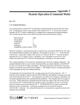
1
AquaTemp Using 8310 & ADAM-4024 4Submersible Temperature Sensor 20mA Output Module May 2014 Sutron Corporation 1 Using Xpert2- 9210B PPP SLL with Janus CDMA Modem 5/15/2014 pg. 2 Overview This Application note will provide the necessary information to connect an ADAM-4024 4-20mA output module to an 8310 data logger's RS485 port and scale four inputs into four 4-20mA outputs. A wiring diagram is included in Appendix A. 2 Items needed: PC with RS-485 to USB converter (Recommended model: Gearmo GM-482422) ADAM 4000 User Manual Advantech Adm/Apax .NET Utility 10-15 Volt Supply 8310 Data Logger Adam-4024 Modbus to 4-20mA output module Sutron Corporation 3 Using Xpert2- 9210B PPP SLL with Janus CDMA Modem 5/15/2014 pg. 3 Configuring the ADAM-4024 The ADAM-4024 must be configured for RS-485 communications, the factory defaults are to communicate in ADAM ASCII protocol. 1. Use the ADAM-4000 utility (latest ADAM-4000 utility can be found at www.advantech.com ) to configure the protocol. 2. With the module powered off, turn the switch in the “Init” position, then power up the module 3. Wait 10 seconds for the module to initialize. 4. Identify the port used by the RS-485 – usb converter. The easiest way to do this is with the utility, start by right clicking on the serial branch and selecting "refresh Nodes". Note the listed ports, then connect the RS-485 converter and repeat the refresh to see what port was added. 5. Connect the RS-485 convert to the ADAM-4024 per wiring diagram in Appendix A. 6. Using the ADAM-4000 utility, right click the appropriate serial com port noted above and search (scan) for the module. (Initial COM settings: 9600 baud, N-8-1) 7. Change the protocol to Modbus, optionally change the address and baud rate (this app note uses the default Address 1 and 9600 baud). 8. Click "Apply Changes" 9. Power off the module. 10. Turn the switch back to NORMAL* position. 11. The module can now be connected to the 8310 4 8310 Setup Sutron Corporation Using Xpert2- 9210B PPP SLL with Janus CDMA Modem 5/15/2014 pg. 4 The 8310 MBOut block will be used to write the registers to the ADAM-4024 to generate the current output. The 8310 will always use the Modbus op code to write multiple registers, even if it is only writing one. While most Modbus slaves will accept this, the ADAM-4024 will not, so we must actually write to all four registers in one write. A simple description of how to set up the 8310 is to have four measurements (the sensors to be converted to a current output), four measurements to scale and assign the sensor data to a local Modbus register, and a single measurement to write the local registers (four scaled measurements) to the ADAM-4024. This example will use a Sutron Accubar CF Bubbler, using the M1 command to retrieve Level (in PSI), temperature, battery voltage and battery voltage under load. 5 Communications The 8310 must first have a communications port defined where the ADAM-4024 will be connected via Modbus. Here, we want the RS-485, which is only available through the optional terminal block Com 4 by setting the RS485 parameter to yes, Communications (5) COM1: (Standby-On) COM2: COM3: COM4: (Started) LAN (Disabled-On) MODBUSTCP (Disabled) End Communications DIRECT NO CONNECT NO CONNECT MODBUS MODBUS COM4 Slave BaudRate Parity Protocol RTSPreDataMS RTSPostDataMS WaitForDSR WaitForCTS RS485 End MODBUS Menu No 9600 None RTU 10 0 No No Yes Sutron Corporation 6 Using Xpert2- 9210B PPP SLL with Janus CDMA Modem 5/15/2014 pg. 5 Measurements An overview of the measurements setup. Measurements (9) M1: Stage Next: M2: AT Next: M3: BV Next: M4: BVLOAD Next: M5: StageOut Next: M6: ATOut Next: M7: BVOut Next: M8: BVLOADOut Next: M9: ADAMOUT Next: Add Measurement Delete Measurement Copy Measurement Move Measurement End Measurements --:--:---:--:---:--:---:--:---:--:---:--:---:--:---:--:---:--:-- Sensors Here, the four parameters returned from the CF Bubbler are read using measurements 1 through 4. For stage, the PSI to water level in feet conversion is done in measurement 1 via a slope of 2.3067. The rest of the measurements are left as scaled from the CF Bubbler. M1: Stage M1: MeasName Enable MeasType Interval Time InputType SDIAddress SDICommand SDIParam Mux SwitchedPwr Processing Slope Offset Cal Slope Cal Offset Cur Val M1.O1: Stage Simulate End M1: Stage Stage Yes Instantaneous 00:15:00 00:00:00 SDI 0 M1 1 None None Slope-Offset 2.3067 0 1 0 0 G 0.000 G Sutron Corporation Using Xpert2- 9210B PPP SLL with Janus CDMA Modem M2: AT M2: MeasName Enable MeasType Interval Time InputType SDIAddress SDICommand SDIParam Mux SwitchedPwr Processing Cal Slope Cal Offset Cur Val M2.O1: AT Simulate End M2: AT AT Yes Instantaneous 00:15:00 00:00:00 SDI 0 M1 2 None None None 1 0 24.88 G 24.88 G M3: BV M3: MeasName Enable MeasType Interval Time InputType SDIAddress SDICommand SDIParam Mux SwitchedPwr Processing Cal Slope Cal Offset Cur Val M3.O1: BV Simulate End M3: BV BV Yes Instantaneous 00:15:00 00:00:00 SDI 0 M1 3 None None None 1 0 0 U 12.00 G 5/15/2014 pg. 6 Sutron Corporation Using Xpert2- 9210B PPP SLL with Janus CDMA Modem 5/15/2014 pg. 7 M4: BVLOAD M4: MeasName Enable MeasType Interval Time InputType SDIAddress SDICommand SDIParam Mux SwitchedPwr Processing Cal Slope Cal Offset Cur Val M4.O1: BVLOAD Simulate End M4: BVLOAD BVLOAD Yes Instantaneous 00:15:00 00:00:00 SDI 0 M1 4 None None None 1 0 0 U 11.00 G Local Modbus Registers These next four measurements are used to define the local Modbus registers and scale them from user units into the appropriate 4-20mA reading. The ADAM-4024 uses a scale of 0 - 4094 to represent the 4 - 20mA output, for a resolution of about 0.004mA. To calculate the slope and offset needed, use the following formula: Slope = (Max Output - Min Output) / (Max Reading - Min Reading) Offset = Min Output - (Min Reading * Slope) *Where Max Output is 4094, Min Output is 0 and Max and Min Reading are the expected range of values for the sensor. For a Stage reading of 0 – 20 feet of water: Slope = (4094 – 0) / (20 – 0) Offset = 0 – (0 * 204.7) Slope = 204.7 Offset = 0 For a Temperature reading of -5 – 40 C: Slope = (4094 – 0) / (40 – -5) Offset = 0 – (-5 * 90.97778) Slope = 90.97778 Offset = 454.8889 For a Battery reading of 10 – 16 Volts (used for both standard and battery under load readings): Slope = (4094 – 0) / (16 – 10) Offset = 0 – (10 * 682.33) Slope = 682.33 Offset = -6823.33 Sutron Corporation Using Xpert2- 9210B PPP SLL with Janus CDMA Modem 5/15/2014 pg. 8 In this example, the local Modbus register selected were 201-204, type is Holding Register, Value Type is ushort and min and max are defaults so the sensor does no extra scaling at 0 and 65535. M5: StageOut M5: MeasName Enable MeasType Interval Time InputType Reference Mux SwitchedPwr Processing Slope Offset Cal Slope Cal Offset Cur Val M5.O1: StageOut Simulate End M5: StageOut StageOut Yes Instantaneous 00:15:00 00:00:00 Reference M1.O1: Stage None None Slope-Offset 204.7 0.0 1 0 3710.188 G 3710.19 G M5.O1: StageOut/MODBUS BaseRegister Type ValueType Min Max LiveReading End MODBUS 201 Holding Register ushort 0 65535 No Sutron Corporation Using Xpert2- 9210B PPP SLL with Janus CDMA Modem M6: ATOut M6: MeasName Enable MeasType Interval Time InputType Reference Mux SwitchedPwr Processing Slope Offset Cal Slope Cal Offset Cur Val M6.O1: ATOut Simulate End M6: ATOut ATOut Yes Instantaneous 00:15:00 00:00:00 Reference M2.O1: AT None None Slope-Offset 90.97778 454.8889 1 0 255.88 G 255.88 G M6.O1: ATOut /MODBUS BaseRegister Type ValueType Min Max LiveReading End MODBUS 202 Holding Register ushort 0 65535 No 5/15/2014 pg. 9 Sutron Corporation Using Xpert2- 9210B PPP SLL with Janus CDMA Modem M7: BVOut M7: MeasName Enable MeasType Interval Time InputType Reference Mux SwitchedPwr Processing Slope Offset Cal Slope Cal Offset Cur Val M7.O1: BVOut Simulate End M7: BVOut BVOut Yes Instantaneous 00:15:00 00:00:00 Reference M3.O1: BV None None Slope-Offset 682.33 -6823.33 1 0 2047.00 G 2047.00 G M7.O1: BVOut /MODBUS BaseRegister Type ValueType Min Max LiveReading End MODBUS 203 Holding Register ushort 0 65535 No 5/15/2014 pg. 10 Sutron Corporation Using Xpert2- 9210B PPP SLL with Janus CDMA Modem M8: BVLOADOut M8: MeasName Enable MeasType Interval Time InputType Reference Mux SwitchedPwr Processing Slope Offset Cal Slope Cal Offset Cur Val M8.O1: BVLOADOut Simulate End M8: BVLOADOut BVLOADOut Yes Instantaneous 00:15:00 00:00:00 Reference M4.O1: BVLOAD None None Slope-Offset 682.33 -6823.33 1 0 1791.13 G 1791.13 G M8.O1: BVLOADOut /MODBUS BaseRegister Type ValueType Min Max LiveReading End MODBUS 5/15/2014 204 Holding Register ushort 0 65535 No pg. 11 Sutron Corporation Using Xpert2- 9210B PPP SLL with Janus CDMA Modem 5/15/2014 pg. 12 Write Modbus Registers to ADAM-4024 Finally, this measurement is used to copy the local scaled Modbus register 201-204 to the ADAM-4024 current output registers (holding registers 1 though 4) at DeviceID 1. M9: ADAMOUT M9: MeasName ADAMOUT Enable Yes MeasType MBOut Interval 00:15:00 Time 00:01:00 DeviceID 1 TargetRegister 1 RegisterType Holding Register ExtendedWrite Yes LocalBaseRegister 201 NumRegisters 4 MBDeviceType Serial COMPort COM4: Timeout 5000 Retries 3 End M9: ADAMOUT Sutron Corporation Using Xpert2- 9210B PPP SLL with Janus CDMA Modem 5/15/2014 Appendix A Wiring 7 8 9 RS-485 Converter to ADAM-4024 Power Supply ADAM-4024 RS-485 to USB (Gearmo specific terminal numbers) GND (B) GND 13 GND (Terminal 5) +V (R) +VS (Y) DATA + RS-485+ (Terminal 1) (G) DATA - RS-485- (Terminal 2) 8310 to ADAM-4024 8310 ADAM-4024 PROT GND (B) GND 13 PROT +12V (R) +VS COM 4 – GND (B) GND 13 COM 4 – 485A (Y) DATA + COM 4 – 485B (G) DATA - ADAM-4024 Current Outputs The ADAM-4024 current outputs are labeled "I OUT", numbered 0-3 (Outputs 1-4) with a + and -. pg. 13