1
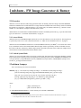
s
ie
og
hn
ol
Mellanox Firmware Tools (MFT)
for Linux and Windows
x
Te
c
User’s Manual
M
el
la
no
Rev 0.65
Mellanox Technologies
2
© Copyright 2008. Mellanox Technologies, Inc. All Rights Reserved.
Mellanox Firmware Tools for Linux and Windows User’s Manual
Document Number: 2329
Mellanox Technologies, Inc.
2900 Stender Way
Santa Clara, CA 95054
U.S.A.
www.mellanox.com
ie
s
Tel: (408) 970-3400
Fax: (408) 970-3403
ol
og
Mellanox Technologies Ltd
PO Box 586 Hermon Building
Yokneam 20692
Israel
M
el
la
no
x
Te
c
hn
Tel: +972-4-909-7200
Fax: +972-4-959-3245
Mellanox Technologies
Rev 0.65
MFT User’s Manual
3
Table of Contents
Table of Contents
Revision History
Chapter 1 Introduction
1.1 Supported Operating Systems
1.2 Supported Mellanox Devices
1.3 MFT Access to Hardware Devices
1.4 Software Prerequisites
1.4.1 On Linux OS
1.4.2 On Windows
1.5 MFT Installation
1.5.1 Install MFT On Linux OS
1.5.1.1 Local Machine Installation
1.5.1.2 RPM Installation
1.5.2 Uninstall MFT (Linux)
1.5.3 Install MFT On Windows OS
1.5.4 Uninstall MFT (Windows)
1.6 Reference Documents and Downloads
Chapter 2 mlxburn - FW Image Generator & Burner
2.1 Overview
2.1.1 Access Modes
2.1.2 Switch System Mode
2.2 mlxburn Synopsys
2.2.1 Additional mlxburn Options
2.3 Firmware Generation and Burning With mlxburn
2.3.1 Firmware Customization
2.4 Examples of mlxburn Usage
2.4.1 Host Channel Adapter Examples
2.4.2 InfiniBand Switch Examples
2.5 Exit Return Values
Chapter 3 flint - HCA Firmware Burner
3.1 Overview
3.2 flint Synopsys
3.2.1 Switch Descriptions
3.2.2 Command Descriptions
3.2.2.1 Burning FW
3.2.2.2 Querying the FW Image
3.2.2.3 Verifying the FW Image
3.2.3 Additional Debug / Production Commands
3.2.3.1 Setting GUIDs and MACs
3.2.3.2 Reading a Word from Flash
Mellanox Technologies
3
5
7
8
9
9
10
10
10
10
10
10
11
11
11
12
12
13
13
13
13
13
15
15
16
16
16
16
17
19
19
19
19
20
21
22
22
23
23
24
Rev 0.65
4
3.2.3.3 Writing a Dword to Flash
3.2.3.4 Writing a dword to Flash Without Sector Erase
3.2.3.5 Erasing a Sector
Chapter 4 spark, ibspark - Switch Firmware Burners
4.1 Overview
4.2 spark
4.2.1 spark Synopsis
4.3 ibspark
4.3.1 Description
4.3.2 Installation
4.3.3 ibspark Synopsis
4.3.4 Usage
Appendix A PSID Assignment
A.1 PSID Field Structure
A.2 PSID Assignment and Integration Flow
Appendix B Flow Examples - mlxburn
B.1 MT47396 In-Band Burning Recommended Flow
B.2 Switch System Burning Flow Example
Appendix C Debug Utilities
C.1 itrace Utility
C.2 mstdump Utility
C.3 isw Utility
C.4 i2c Utility
Rev 0.65
Mellanox Technologies
24
24
25
27
27
27
27
29
29
29
29
29
31
31
31
33
33
34
37
37
39
39
40
MFT User’s Manual
5
Revision History
Printed on July 16, 2008.
Table 1 - Revision History Table
Date
Revision
April 2008
0.65
August 2007
June 2007
January 2007
January 2006
October 2005
0.60
0.50
0.40
0.30
0.20
Description
•
Added MFT installation instruction in Section 1.5, “MFT Installation,” on page 10
•
mlxburn tool: added Expansion ROM auto-detection description
•
flint tool: added the ‘-blank_guids’ flag and the ‘sg’ command
•
Added Section 3.2.3.1 describing how to set GUIDs/MACs on a Flash device with blank GUIDs/
MACs
•
Updated tool usage examples to use ConnectX devices
•
Added Appendix C, “Debug Utilities”
•
Added the ‘-mac’ flag to the flint and mlxburn tools to support the ConnectX EN 10GigE adapter
•
Added Section 4.3, “ibspark,” on page 29 that describes ibspark, the In-Band firmware burning
tool for InfiniScale III switches
•
Modified Chapter 2, “mlxburn - FW Image Generator & Burner” on page 13 to describe mlxburn
support for burning switch systems with multiple InfiniScale / InfiniScale III switch devices
•
Added Appendix B, “Flow Examples - mlxburn” to describe burning switches In-Band and via a
direct I2C connection
•
MFT for Windows is now part of the WinIB software package; therefore, to install MFT on a
Windows machine, you need to install WinIB and enable MFT. See Section 1.5.3, “Install MFT
On Windows OS,” on page 11.
•
Added flint flag: -use_image_ps
•
Removed flint flags: -crc, -bsn
(MFT version 1.0.1)
• Added querying options for VPD for mlxburn
•
Added examples to demonstrate support of MT43132 InfiniScale device by mlxburn and spark
•
Reorganized the “flint - HCA Firmware Burner’ (page
•
Added the Appendix “PSID Assignment” on page 31.
19) chapter
Added Windows distribution to MFT (MFT version 0.5.1)
Added the following sections:
• Section 1.1, “Supported Operating Systems,” on page 8
August 2005
0.10
•
Section 1.3, “MFT Access to Hardware Devices,” on page 9
•
Section 1.4, “Software Prerequisites,” on page 10
•
Section 1.5, “MFT Installation,” on page 10
First release (Linux distribution only) (MFT version 0.5.0)
Mellanox Technologies
Rev 0.65
6
Rev 0.65
Mellanox Technologies
MFT User’s Manual
7
1 Introduction
The Mellanox Firmware Tools (MFT) package is a set of firmware management tools for a single InfiniBand node.
MFT can be used for:
• Generating a standard or customized Mellanox firmware image
• Querying for firmware information
• Burning a firmware image to a single InfiniBand node
The following is a list of the available tools in MFT, together with a brief description of what each tool performs. See
Figure 1 on page 8 for an illustration of the tools’ scheme of operation.
mlxburn
This tool provides the following functions:
• Generation of a standard or customized Mellanox firmware image for burning (in binary or .mlx
format)
• Burning an image to the Flash/EEPROM attached to a Mellanox HCA or switch device
• Querying the firmware version loaded on an HCA board
• Displaying the VPD (Vital Product Data) of an HCA board
flint
This tool burns a firmware binary image to the Flash(es) attached to an HCA board. It includes
query functions to the burnt firmware image and to the binary image file.
spark
This tool burns a firmware binary image to the EEPROM(s) attached to a switch device. It includes
query functions to the burnt firmware image and to the binary image file. The tool accesses the
EEPROM and/or switch device via an I2C-compatible interface.
ibspark
This tool burns a firmware binary image to the EEPROM(s) attached to a switch device. It includes
query functions to the burnt firmware image and to the binary image file. The tool accesses the
switch device and the EEPROM via vendor-specific MADs over the InfiniBand fabric (In-Band
tool).
Debug utilities
A set of debug utilities (e.g., itrace, mstdump, isw, and i2c)
Mellanox Technologies
Rev 0.65
Introduction
8
Figure 1: Mellanox Firmware Tools – A Scheme of Operation
mlxburn
InfiniBand
spark
Switch System
I²C
EEP
EEP
EEP
EEP
Mellanox
USB-to- I²C
Adapter
flint
MST
ibspark
OFED
USB
Mellanox
Switch
Adapter
Mellanox IB Adapter
IB
IB
IB
IB
IB
PCI
IB
InfiniBand
Fabric
Note: The ibspark flow is not supported by Mellanox Ethernet Adapters
1.1 Supported Operating Systems
Two distributions of MFT are available: for Linux and for Windows. Please refer to the release notes of your version
for supported platforms and kernels.
Note: Unless explicitly specified, the usage of the tools is identical for both operating systems.
Rev 0.65
Mellanox Technologies
MFT User’s Manual
9
1.2 Supported Mellanox Devices
Table 1 - Supported Mellanox Devices
Device Type
HCA (InfiniBand)
Product Name
MT23108 InfiniHost
Supporting Tools
mlxburn, flint
MT25208 InfiniHost III Ex
MT25204 InfiniHost III Lx
MT25408 ConnectX IB 1
Ethernet Adapter (NIC)
MT25408 ConnectX EN
Switch
MT47396 InfiniScale III
mlxburn, spark, ibspark
MT43132 InfiniScale
mlxburn, spark
1. ConnectX IB devices support the Multi-Protocol feature.
1.3 MFT Access to Hardware Devices
MFT tools access HCA devices via the PCI-X / PCI Express interface, via a USB to I2C adapter (Mellanox P/N:
MTUSB-1), or via vendor-specific MADs
The tools access switch devices via a USB to I2C adapter, via vendor-specific MADs over the InfiniBand fabric (InBand).
Note: In-Band device access requires installing the MFT package with the ‘--enable-inband’ flag, and that
the local IB port is connected to an IB fabric and is in the ACTIVE state.
All MFT tools address the target hardware device using an mst device name. On Linux, this name is assigned by running the command ‘mst start’.
On Windows:
1. To access an HCA device via the PCI bus: If the IBAL driver is installed and running, the name is already
assigned.
2. To access an HCA or switch device via the USB bus: A USB to I2C Adapter should be used to connect the host
USB port and the I2C port of the target device. Upon the first usage of this interface, you will be requested to
install the USB to I2C Adapter driver (I2CBridge1).
To list the available mst device names on the local machine, run ‘mst status’ (on both OSes). (Note that In-Band
device names are not listed by this command.)
The format of an mst device name is as follows:
Via PCI:
mt<dev-id>_pci<_crX|confX>
where:
X is the index of the HCA on the machine.
_crX devices access the HCA directly (recommended if possible)
confX devices use configuration cycles to access the HCA
Via USB to I2C adapter: For example, mtusb-1
1. Visit http://www.xdimax.com to download this driver.
Mellanox Technologies
Rev 0.65
Introduction
10
Via the InfiniBand fabric:
• For ibspark only: the switch device is accessed In-Band via the InfiniBand fabric by the device LID
• For all other tools: the target device is accessed In-Band via the InfiniBand fabric by the concatenating the string
‘lid-’ to the actual device LID (e.g., lid-0x13)
• See Step 3 in Appendix B,“Flow Examples - mlxburn,” on page 33 for instructions on how to obtain the device
LID
1.4 Software Prerequisites
1.4.1 On Linux OS
Table 2 - MFT Software Dependencies on Linux
Software Package
Required Version
Perl
5.6 or later
Expat
1.95 or later
zlib
1.1.4 or later
Kernel sources
Machine’s kernel version
OFED1
1.1 or later
1. OFED is required for the optional installation of ibspark only. OFED can be downloaded
from http://www.openfabrics.org.
1.4.2 On Windows
Table 3 - MFT Software Dependencies on Windows
Software Package
Required Version
WinIB
1.2.0 or later
I2CBridge1
(Dimax’s Driver for USB to I2C Adapter)
0.1.4 or later
1. Visit http://www.xdimax.com to download this driver.
1.5 MFT Installation
1.5.1 Install MFT On Linux OS
You can either download the MFT tarball to your local machine and install MFT, or—in case you plan to install MFT
on a cluster—you can download the MFT tarball, build an RPM, and install it on the cluster machines.
1.5.1.1 Local Machine Installation
1.
2.
3.
Download the Linux MFT package from the Mellanox Management Tools webpage:
http://www.mellanox.com/products/management_tools.php
Untar the downloaded package
Run ‘install.sh’
Note: To install ibspark run ‘install --with-ibspark’. Make sure OFED is already installed on your machine.
4.
Start the mst driver by entering: mst start
Rev 0.65
Mellanox Technologies
MFT User’s Manual
11
Note: It is possible to customize some parameters of the installation (such as the target installation path).
Run ‘install.sh --help’ for details.
1.5.1.2 RPM Installation
1.
Download the Linux MFT package from the Mellanox Management Tools webpage:
http://www.mellanox.com/products/management_tools.php
2.
Build the RPM:
For MFT with neither ibspark nor In-Band support, run:
> rpmbuild -tb mft-2.1.0.tgz
For MFT with ibspark and In-Band support (requires a Mellanox OFED driver1 installation):
> rpmbuild -tb mft-2.1.0.tgz -D 'inband 1'
As a result of the rpmbuild command, the MFT RPM will be created under the RPMS directory. This dorectory is
located under:
• RedHat: /usr/src/redhat/RPMS
• SuSe: /usr/src/packages/RPMS
3.
To install the RPM, run:
> rpm -i /usr/src/packages/RPMS/x86_64/mft-2.1.0-2.6.16.21_0.8_smp.x86_64.rpm
Repeat Step 3 to install the MFT RPM on other hosts in the cluster with an identical configuration (OS, kernel,
installed packages).
4.
Start the mst driver by entering: mst start
1.5.2 Uninstall MFT (Linux)
If you installed MFT using the install script (described in Section 1.5.1.1), run:
> uninstall_mft.sh
Note: The script uninstall_mft.sh is located under the same directory of the other MFT executables.
If you installed MFT from an RPM, run:
> rpm -e mft
1.5.3 Install MFT On Windows OS
MFT for Windows is provided as part of the Mellanox Technologies WinIB software package. If WinIB is installed
on your machine2 and you wish to check whether MFT is installed too, open a console window and run:
‘mlxburn -v’.
In case an error is returned by the command, then MFT is not installed on your machine. To install it, activate the
‘Add or Remove Programs’ utility of Windows and click the ‘Change’ button. Select ‘Modify’ on the Program Maintenance pop-up menu, and enable the following components:
•Driver
•MFT
1. See www.mellanox.com
2. That is, you can locate the program ‘MellanoxWinIB32/64’ using the ‘Add or Remove Programs’ utility of Windows.
Mellanox Technologies
Rev 0.65
Introduction
12
In case WinIB is not installed on your machine, download it via http://www.mellanox.com and perform either a ‘Custom’ or a ‘Complete’ installation. If you choose a Complete installation of WinIB, MFT will be installed in the process. If you choose a Custom installation, make sure you enable the Driver and MFT components.
1.5.4 Uninstall MFT (Windows)
To uinstall MFT, activate the ‘Add or Remove Programs’ utility of Windows and click the ‘Change’ button. Select
‘Modify’ on the Program Maintenance pop-up menu, and disable MFT.
1.6 Reference Documents and Downloads
•
•
•
To download firmware images and their release notes, see http://www.mellanox.com under ‘Firmware’ downloads.
Mellanox OFED is a software stack that can be downloaded from http://www.mellanox.com under ‘OFED’
downloads.
ibdiag tools – run ‘man ibdiagnet’ for details on a machine with OFED installed.
Rev 0.65
Mellanox Technologies
MFT User’s Manual
13
2 mlxburn - FW Image Generator & Burner
2.1 Overview
mlxburn is a tool for firmware (FW) image generation and/or for burning a firmware image to the Flash/EEPROM
attached to a Mellanox device. Both functions or a single function of mlxburn can be activated by means of command
line options (see Section 2.2, “mlxburn Synopsys”). It can also query for firmware attributes (e.g., firmware version,
GUIDs, etc.) and VPD info of adapter cards and switch systems.
mlxburn allows for cusomization of standard Mellanox firmware for OEM specific needs (e.g., a specific HCA board
type). See Section 2.3.1, “Firmware Customization,” on page 16.
2.1.1 Access Modes
mlxburn can access an InfiniBand adapter (HCA) device via its PCI interface (over the mst driver). The target device
is specified by an mst device name (described in Section 1.3, “MFT Access to Hardware Devices,” on page 9).
mlxburn can access InfiniBand switch devices via the InfiniBand connectivity (In-Band)1 or via a direct I2C connectivity. If mlxuburn accesses the switch In-Band, then the target switch is specified by its LID2. If mlxburn accesses
the switch via the I2C connectivity, then the target switch is specified by the name of the USB to I2C adapter device3
connected between the mlxburn host machine and the switch.
2.1.2 Switch System Mode
mlxburn can query and update parts of or an entire switch system. This mode of the tool requires familiarity with the
target switch system’s topology, and it can be applied to the following switch systems: MTPDK24 or MTPDK16 (24or 16-port Reindeer), 96 port MTS9600 (Gazelle), MTPDK144 (144-port Rhino), and MTPDK288 (288-port Trex).
See the -sw_sys flag in Section 2.2 below.
2.2 mlxburn Synopsys
Note: You must log in as root to run mlxburn.
mlxburn [-h][-v] <-dev mst-device|-wrimage fw-image> <-fw mellanox-fw-file|-image fw-image>
[-conf fw-conf-file][-nofs][-nofs_img][-format BINARY|IMAGE][-dev_type device-type]
[-exp_rom <exp_rom_file>][-exp_rom_dir <exp_rom_dir>][-force][-conf_dir]
[-fwver][-vpd][-vpd_rw][-vpd_prog_rw <rw-fields-file>][-query][-inband]
[-sw_sys <rhino|reindeer|trex|gazelle> [-pattern <geo-addr> | -list]]
where:
-h
- display a short help text
-v
- print version info and exit
-V <INFORM|WARNING|DEBUG>- set the verbosity level. Default is WARNING.
1. MT47396 InfiniScale III devices only.
2. The LID is assigned by the Subnet Manager which is part of OFED. See “Reference Documents and Downloads” on page 12.
3. For example, mtsub-1. Run ‘mst status’ to obtain the device name.
Mellanox Technologies
Rev 0.65
mlxburn - FW Image Generator & Burner
14
-dev <mst-dev | LID>
- access the device using the MST device name or the LID (see the -inband flag)
-wrimage <fw-image-file>
- write the generated binary image to the provided file name
-fw <mellanox-fw-file>
- specify the Mellanox firmware file to use (file extension is .mlx)
-format <BINARY|IMAGE>
- specify which image format to use. Can be used only with the -wrimage flag.
Default is BINARY.
-image <fw-image-file>
- use the given firmware image to burn (file extension is .bin or .img)
-conf <parameter-set-file>
- firmware configuration file (.ini). Needed for image generation (not using the -dev
flag) or if auto-detection of configuration fails.
-conf_dir <dir>
- instruct the burn operation to look for auto-detected configuration files under the
specified directory rather than under the firmware file directory.
-nofs
- when specified, the burn process will not be failsafe. A non-failsafe burn is
required (on the rare occasion) when a new firmware version has modifications in
the Invariant Sector
-nofs_img
- when specified, the generated image will not be failsafe. If burning is also specified, it will not be failsafe either.
-exp_rom <exp-rom-file>
- Integrate the given expansion rom file to the FW image. The given file may be in
.img or .bin/.rom (raw binary) format. If the exp-rom-file is set to "AUTO", expansion rom file is auto detected from the files rom in the exp_rom_dir (see below).
NOTE: Exp rom auto detection is done for devices that are already burned with an
exp-rom image. If "-exp_rom AUTO" is specified for a device with no exp-rom, it
would be burnt with no exp rom. To add exp-rom to a device, manually supply the
exp rom file to use.
-exp_rom_dir <exp_rom_dir> The directory in which to look for expansion rom file when "-exp_rom AUTO" is
specified. By default, exp-rom files are searched in <fw file directory>/exp_rom/*
-fwver
- When a device is given: Display current loaded firmware version. When a FW file
is given (-fw flag): Display the file FW version.
-force
- run mlxburn in non-interactive mode
-vpd 1
- display the Read Only section of the PCI VPD (Vital Product Data) of the given
device
-vpd_rw 1
- display the Read Only and Read/Write sections of the PCI VPD of the given device
-vpd_prog_rw 1 <rw-fields-file>- program the VPD-W tag (the writable section of the VPD) with the data given in
the rw-fields-file. File lines format is "FIELD = VALUE". White spaces before and
after VALUE are trimmed. A field name should have 2 letters exactly (for example: "YA" , "V1"). The field name "RW" is reserved and should not be used.
-query
- query adapter or switch devices for firmware information
-inband
- Use the In-Band access method (query/burn). This is applicable only when burning
an InfiniScale III (MT47396) switch device. When using this flag, the argument of
the -dev flag should be the LID of the target InfiniScale III device. See Section B.1,
“MT47396 In-Band Burning Recommended Flow,” on page 33 for a flow example.
1. The VPD query may not be enabled on certain board types.
Rev 0.65
Mellanox Technologies
MFT User’s Manual
15
Note: The ‘-inband’ flag is supported only if the MFT package is installed with the ‘--with-ibspark’ flag.
-sw_sys <switch_type> [-pattern <geo-addr> | -list ]
- Specify a switch system type: gazelle (96 ports), reindeer (24 or 16 ports), rhino
(144 ports), or trex (288 ports).
Use the -pattern flag to specify the system’s target device(s) using the georgraphical name(s); for example, S1I1 (Device 1 on Spine 1), L12I1 (Device 1 on Leaf
12), L* (all switch Leafs) — run ‘isw -h’ for further details on patterns.
The -list flag lists all the InfiniBand devices of the switch system using their geographical names. The -list flag inhibits all other mlxburn functions.
-dev_type <Mellanox-Device-ID>- mlxburn must know the Mellanox device ID in order to work properly. This
option should be used if auto-detection of the device type (taken from the firmware
file) fails. The following is the list of supported device IDs:
23108 - For MT23108 InfiniHost based HCA cards (Cougar family)
25208 - For MT25208 InfiniHost III Ex in InfiniHost-mode (with local attached
memory) HCA cards (Lion Cub family)
25218 - For MT25208 InfiniHost III Ex in MemFree-mode HCA cards (Lion
Mini family)
25204 - For MT25204 InfiniHost III Lx HCA cards (Tiger/Cheetah families)
25408 - For MT25408 ConnectX IB Dual 10Gb/s InfiniBand Port Adapter Cards
25418 - For MT25408 ConnectX IB Dual 20Gb/s InfiniBand Port Adapter Cards
25448 - For MT25408 ConnectX EN (NIC) cards
43132 - For MT43132 InfiniScale based switch systems
47396 - For MT47396 InfiniScale III based switch systems
2.2.1 Additional mlxburn Options
The following is a list of additional options. Please see Chapter 3, “flint - HCA Firmware Burner,” on page 19 for the
HCA options, and Chapter 4, “spark, ibspark - Switch Firmware Burners,” on page 27 for the switch options.
For HCA1: [-byte_mode] [-use_image_ps] [-skip_is] [-mac(s)] [-guid(s)] [-sysguid] [-vsd]
For switches2: [-guid] [-sysguid] [-ndesc] [-bsn] [-pe_i2c] [-se_i2c] [-is3_i2c]
2.3 Firmware Generation and Burning With mlxburn
The mlxburn firmware update flow is composed of two separate stages: image generation and image burning. In the
image generation stage, a given Mellanox firmware release (in .mlx format for HCAs and in .BIN format for
switches) is processed together with a board-specific configuration (.ini) file to generate a ‘burnable’ firmware image.
This image is burnt to the Flash/EERPROM attached to a Mellanox device in the second stage. The burning process
retains device specific data such as GUIDs, MACs, VSD, and BSN. Also, the burn process is failsafe by default.
1. The arguments of the -guids and -macs flags must be provided within quotation marks; for example,
mlxnburn -macs “0002c900001 0002c900002”
2. The -guid flags is supported by all Mellanox Technologies’ switch devices. All other flags are supported by the MT47396
InfiniScale III devices only.
Mellanox Technologies
Rev 0.65
mlxburn - FW Image Generator & Burner
16
mlxburn runs both stages by default, but it may perform only one by means of command options. If the ‘-wrimage’ is
specified (see Section 2.2, “mlxburn Synopsys”), only image generation is performed. Specifying the ‘-image’ option
skips the image generation stage and loads the provided image (generated in a previous run of mlxburn using the
‘-wrimage’ option).
Note: When generating an image file for a Mellanox switch device, the produced image file name must end
with a .img extension.
2.3.1 Firmware Customization
A Mellanox firmware image can be customized (usually) to fit a specific board type. The customization is done by
using a FW parameter-set file in the image generation stage. This file has a .ini format. Each parameter-set file has a
unique parameter-set ID (PSID), which is kept in the device Flash/EEPROM and allows retaining device configuration during future FW updates.
During a device FW update, mlxburn reads the PSID from the device and uses the corresponding .ini file when generating the FW image. mlxburn searches for the files in the same directory of the FW release. When mlxburn is used
to generate an image file, or when no corresponding parameter-set file is found, the user should explicitly specify
which parameter-set file to use.
To produce an image file the user needs to provide the option ‘-wrimage <target file>’. To actually burn the image to
the Flash/EEPROM attached to a Mellanox HCA or switch device, the user needs to specify the option ‘-dev </dev/
mst/dev-file>’.
If run in burning mode, mlxburn auto-detects the firmware parameter-set with which the device was previously
burnt. It locates and uses this parameter-set file to generate the appropriate image for the device (by merging the FW
release with the specific parameter-set required).
To inhibit image generation, the ‘-image <pre-generated-image-file>’ should be used. It instructs mlxburn to use the
given file for burning the device.
2.4 Examples of mlxburn Usage
2.4.1 Host Channel Adapter Examples
•
To update firmware on an MT25408 ConnectXTM IB (HCA) device with the configuration file (.ini) autodetected, enter:
mlxburn -fw ./fw-25408-rel.mlx -dev /dev/mst/mt25418_pci_cr0
•
To generate a failsafe image file for the same HCA above without burning, enter:
mlxburn -fw ./fw-25408-rel.mlx -conf ./MHEH28-XTC_A1.ini -wrimage ./fw-25418.bin
•
To update firmware on the same HCA above with the configuration file (.ini) explicitly specified, enter:
mlxburn -fw ./fw-25408-rel.mlx -dev /dev/mst/mt25418_pci_cr0
-conf ./MHEH28-XTC_A1.ini
•
To burn a firmware binary file for an MHGA28-1T (Lion Cub 128MB DDR) HCA card, enter:
mlxburn -image ./fw-25208-4_8_200-MHGA28-1T.bin -dev /dev/mst/mt25208_pci_cr0
-dev_type 25208
2.4.2 InfiniBand Switch Examples
•
To update firmware on an MT47396 InfiniScale III device, enter:
Rev 0.65
Mellanox Technologies
MFT User’s Manual
17
mlxburn -fw IS3FW.BIN -dev /dev/mst/mtusb-1
Note: This firmware update cannot be performed before initializing the MST device (mtusb-1) to connect to
the I2C-compatible bus of the InfiniScale III and its EEPROM.
•
To generate an image for the InfiniScale III switch device, enter:
mlxburn -fw IS3FW.BIN -conf ./MTS2400-A00.INI -wrimage IS3FW.img
Note: The generated firmware image to be burnt to a switch device must have a ‘.img’ file name extension.
•
To update firmware on an MT43132 InfiniScale device in a switch system such as Flextronics’ F-X430066 Stallion 8 4X IB port switch, enter:
mlxburn -image Stallion_5_5_0.eeprom -dev /dev/mst/mtusb-1 -dev_type 43132
Note: This firmware update cannot be performed before initializing the MST device (mtusb-1) to connect to
the I2C-compatible bus of the InfiniScale and its EEPROM.
•
To list all detected switch devices (in the format of patterns) that are currently connected to the 144 port Rhino
system chassis, enter:
mlxburn -dev /dev/mst/mtusb-1 -sw_sys rhino -list
•
To perform a full query of a 144 port Rhino switch system, enter:
mlxburn -dev /dev/mst/mtusb-1 -sw_sys rhino -pattern -query
•
To generate and burn an MT47396 image for device number 3 on Spine number 1 of the 288 port Trex system,
enter:
mlxburn -dev /dev/mst/mtusb-1 -sw_sys trex -pattern S1I3 -fw ./IS3FW.BIN
•
To generate an MT47396 image and perform an In-Band update of the device with LID 0x11, enter:
mlxburn -dev 0x11 -fw ./IS3FW.BIN -inband
2.5 Exit Return Values
The following exit values are returned:
0
- successful completion
>0 - an error occurred
Mellanox Technologies
Rev 0.65
mlxburn - FW Image Generator & Burner
18
Rev 0.65
Mellanox Technologies
MFT User’s Manual
19
3 flint - HCA Firmware Burner
3.1 Overview
The flint (Flash interface) utility performs the following functions:
• Burns a binary firmware image to the Flash attached to an HCA device
• Queries for HCA firmware attributes (version, GUIDs, PSID, etc.)
• Enables executing various operations on the Flash memory from the command line (for debug/production)
3.2 flint Synopsys
flint [switches...] <command> [parameters...]
3.2.1 Switch Descriptions
-d[evice] <device>
- The device to which the Flash is connected.
Affected commands: All
-i[mage] <image>
- Binary image file.
Affected commands: burn, verify
-guid <GUID>
- Base value for up to 4 GUIDs which are automatically assigned the following values:
guid -> node GUID
guid+1 -> port1
guid+2 -> port2
guid+3 -> system image GUID.
Affected commands: burn sg
-guids <GUIDs...>
- 4 GUIDs must be specified here. These GUIDs will be assigned to:
node, port1, port2 and system image GUID respectively.
Affected commands: burn sg
-mac <MAC> 1
- MAC base address value. Each of the two ConnectX EN ports is assigned a MAC
address as follows:
MAC
is assigned to Port 1
MAC+1 is assigned to Port 2
Affected commands: burn sg
-macs <MACs...>
1
- 2 MAC addresses must be specified here—one for each ConnectX EN port. The
first MAC address is assigned to Port 1 and the second MAC address to Port 2.
Affected commands: burn sg
-blank_guids
- Burn the image with blank GUIDs and MACs (where applicable). These values can
be set later using the “sg” command (see details below).
NOTE: An image that is burnt with blank GUIDs/MACs will fail to boot the
machine as long as the GUIDs/MACs are not set.
1. The -mac and -macs options are applicable only to Mellanox Technologies Ethenet adapter devices.
Mellanox Technologies
Rev 0.65
flint - HCA Firmware Burner
20
Affected commands: burn
-clear_semaphore
- Force the clearing of the Flash semaphore on the device. This flag should come
BEFORE the -d[evice] flag in the command line. No command is allowed when
this flag is used.
NOTE: Using this flag may result in an unstable behavior and flash image corruption if the device or another flash application is currently using the flash. Handle
with care.
-byte_mode
- Shift the address when accessing Flash internal registers. May be required for burn/
write commands when accessing certain Flash types.
-h[elp]
- Print this message and exit.
-hh
- Print extended command help.
-nofs
- Do not burn image in failsafe mode.
-skip_is
- Allow burning the FW image without updating the invariant sector to ensure failsafe burning even if the invariant sector of the image is different from the one burnt
on the Flash.
Note: Some FW releases may include important changes to the invariant sector that
must be included in the FW update process. In these cases, the -skip_is flag should
not be used. Please refer to the specific FW release notes for details.
-s[ilent]
- Print errors only.
Affected commands: burn
-y[es]
- Non-interactive mode. Assume the answer "yes" to all questions.
Affected commands: all
-no
- Non-interactive mode. Assume the answer "no" to all questions.
Affected commands: all
-vsd <vendor-specific-data>
-A VSD string, composed of up to 208 characters, will be written to the VSD
section in the flash. If not specified, the current VSD will be preserved.
-use_image_ps
- Burn vsd as it appears in the given image. (Default: Retain current vsd on Flash.)
Affected commands: burn
-v
- Version information.
3.2.2 Command Descriptions
The flint utility commands are:
b[urn]
- Burn flash
e[rase]
- Erase sector
q[uery]
- Query for misc. Flash/firmware characteristics
rw
- Read one dword from flash
v[erify]
- Verify entire flash
ww
- Write one dword to flash
bb
- Burn Block - Burns the given image as is. No checks are done.
sg
- Set GUIDs
wwne
- Write one dword to flash without sector erase
wbne
- Write a data block to flash without sector erase
rb
- Read a data block from flash
Rev 0.65
Mellanox Technologies
MFT User’s Manual
21
ri
- Read the fw image on the flash.
dc
- Dump Configuration: print fw configuration file for the given image.
The following sections provide the command line syntax for the following flint utility commands, together with
examples of usage.
• Burning FW (page 21)
• Querying the FW Image (page 22)
• Verifying the FW Image (page 22)
3.2.2.1 Burning FW
The FLINT utility enables you to burn the Flash from a binary image.
To burn the entire Flash from a raw binary image, use the following command line:
flint -d <device> -i <fw-file> [-guid <GUID> | -guids <4 GUIDS> | -mac <MAC> |
-macs <2 MACs>] burn
where:
device – Device on which the flash is burned.
fw-file – Binary firmware file.
GUID (optional, for InfiniBand HCAs only) – One or four GUIDs.
If 4 GUIDS are provided (-guids flag), they will be assigned as node, Port 1, Port 2 and system image GUIDs,
respectively.
If only one GUID is provided (-guid flag), it will be assigned as node GUID. Its values +1, +2 and +3 will be
assigned as Port 1, Port 2 and system image GUID, respectively.
If no -guid/-guids flag is provided, the current GUIDs will be preserved on the device.
Note: A GUID is a 16-digit hexadecimal number. If less than 16 digits are provided, leading zeros will be
inserted.
MAC (optional, for Ethernet adapters only) – One or two MACs.
If 2 MACs are provided (-macs flag), they will be assigned to Port 1 and Port 2, respectively.
If only one MAC is provided (-mac flag), it will be assigned to Port 1; MAC+1 will be assigned to Port 2.
If no -mac/-macs flag is provided, the current LIDs will be preserved on the device.
Note: A MAC is a 12-digit hexadecimal number. If less than 12 digits are provided, leading zeros will be
inserted.
Examples:
1.
Update the FW on the device, keeping the current GUIDs and VSD. (Note: This is the common way to use flint.)
> flint -d /dev/mst/mt25418_pci_cr0 -i fw-25408-2_1_000-MHGH28-XSC_A1.bin burn
2.
Update the FW on the device, specifying the GUIDs to burn.
> flint -d /dev/mst/mt25418_pci_cr0 -i 25408-2_1_000-MHGH28-XSC_A1.bin
-guid 12345678deadbeef burn
Mellanox Technologies
Rev 0.65
flint - HCA Firmware Burner
22
3.
Update the FW on the device, specifying the MACs to burn.
> flint -d /dev/mst/mt25448_pci_cr0 -i fw-25448-6_0_111-MNEH28-XTC_A1.bin
-mac 12345678beef burn
4.
Burn the image on a blank Flash device. This means that no GUIDs are cuurently burnt on the device, therefore
they must be supplied (with -guid/-guids) by the burning command. Moreover, the burn process cannot be failsafe when burning a blank Flash, therefore the -nofs flag must be specified.
> flint -d /dev/mst/mt25418_pci_cr0 -i 25408-2_1_000-MHGH28-XSC_A1.bin -nofs
-guid 1234567812345678 burn
5.
Read FW from the device and save it as an image file.
> flint -d /dev/mst/mt25418_pci_cr0 ri Flash_Image_Copy.bin
3.2.2.2 Querying the FW Image
To query the FW image on a device, use the following command line:
flint -d <device> q
To query the FW image in a file, use the following command line:
flint -i <image file> q
where:
device – Device on which the query is run.
image file – Image file on which the query is run.
Examples:
1.
Query the FW on the device.
> flint -d /dev/mst/mt25418_pciconf0 query
2.
Query the FW image file.
> flint -i 25408-2_1_000-MHGH28-XSC_A1.bin query
3.2.2.3 Verifying the FW Image
To verify the FW image on the Flash, use the following command line:
flint -d <device> v
To verify the FW image in a file, use the following command line:
flint -i <image file> v
where:
device is the Flash device to verify, and
image file is the image file to verify
Examples:
flint -d /dev/mst/mt25418_pci_cr0 v
flint -i ./image_file.bin v
Rev 0.65
Mellanox Technologies
MFT User’s Manual
23
3.2.3 Additional Debug / Production Commands
3.2.3.1 Setting GUIDs and MACs
To set GUIDs/MACs for the given device, use the ‘sg’ command with the -guid(s) and/or -mac(s) flags.
This command is applicable only for images with blank (0xff) GUID/MAC values and a blank CRC. In other words,
the firmware image was generated using the ‘-blank_guids’ flag. The following is an example of a complete flow,
where a blank-GUIDs image is first generated and burnt to the Flash. Then the GUIDs are set using the ‘sg’ command.
1.
Generate the image with blank guids.
Note: For ConnectX devices, you must specify the ‘-striped_image’ flag if you intend to burn the image with
the ‘bb’ (block-burn) command.
> mlxburn -fw ./fw-25408-rel.mlx -c ./MHGH28-XTC_A1.ini -wrimage \
/tmp/fw-25408-rel-2_3_000-MHGH28-XTC_A1-noguids.bin -striped_image -blank_guids
-I- Generating image ...
-I- Image generation completed successfully.
2.
Query the image to verify that the GUIDs and MACs are blank.
> flint -i /tmp/fw-25408-rel-2_3_000-MHGH28-XTC_A1-noguids.bin q
Image type:
ConnectX
FW Version:
2.3.0
Device ID:
25418
Chip Revision:
A0
Description:
Node
Port1
Port2
Sys image
GUIDs:
ffffffffffffffff ffffffffffffffff ffffffffffffffff ffffffffffffffff
MACs:
ffffffffffffffff ffffffffffffffff
Board ID:
n/a (MT_04A0110002)
VSD:
n/a
PSID:
MT_04A0110002
Warning: GUIDs/MACs values and their CRC are not set.
>
3.
Burn the blank-GUIDs image. This image can be pre-burnt on the flash in an early production phase.
In this example, the ‘flint bb’ command is used in order to burn the image as is.
> flint -d /dev/mst/mt25418_pci_cr0 -i /tmp/fw-25408-rel-2_3_000-MHGH28-XTC_A1noguids.bin bb
Block burn: The given image will be burnt as is. No fields (such
as GUIDS,VSD) are taken from current image on flash.
Burn process will not be failsafe. No checks will be performed.
ALL flash, including the Invariant Sector will be overwritten.
If this process fails, computer may remain in an inoperable state.
Do you want to continue ? (y/n) [n] : y
100%
Mellanox Technologies
Rev 0.65
flint - HCA Firmware Burner
24
4.
Set the GUIDs and MACs using the ‘flint sg’ command.
> flint -d /dev/mst/mt25418_pci_cr0 -guid 0x0002c90001777050 -mac 0x0002c9777051 sg
5.
Query the image on the Flash to verify that the GUIDs and MACs were set correctly.
> flint -d /dev/mst/mt25418_pci_cr0 q
Image type:
ConnectX
FW Version:
2.3.0
Device ID:
25418
Chip Revision:
A0
Description:
Node
Port1
Port2
Sys image
GUIDs:
0002c90001777050 0002c90001777051 0002c90001777052 0002c90001777053
MACs:
0002c9777051
0002c9777052
Board ID:
n/a (MT_04A0110002)
VSD:
n/a
PSID:
MT_04A0110002
3.2.3.2 Reading a Word from Flash
To read one dword from Flash memory, use the following command line:
flint -d <device> rw addr
where:
device is the device the dword is read from.
addr is the address of the word to read.
Example:
flint -d /dev/mst/mt23108_pci_cr0 rw 0x20
3.2.3.3 Writing a Dword to Flash
To write one dword to Flash memory, use the following command line:
flint -d <device> ww addr data
where:
device is the device the dword is written to.
addr is the address of the word to write.
data is the value of the word.
Example:
flint -d /dev/mst/mt23108_pci_conf01 ww 0x10008 0x5a445a44
3.2.3.4 Writing a dword to Flash Without Sector Erase
To write one dword to Flash memory without sector erase , use the following command line:
flint -d <device> wwne addr data
where:
device – the device the dword is written to.
Rev 0.65
Mellanox Technologies
MFT User’s Manual
25
addr – the address of the word to write.
data – the value of the word.
Example:
flint -d /dev/mst/mt23108_pci_cr0 wwne 0x10008 0x5a445a44
Note that a result may be dependent on the Flash type. Usually, bitwise and between the specified word and the previous Flash contents will be written to the specified address.
3.2.3.5 Erasing a Sector
To erase a sector that contains a specified address, use the following command line:
flint -d <device> e addr
where:
device is the device the sector is erased from, and
addr is the address of a word in the sector that you want to erase.
Example:
flint -d /dev/mst/mtusb-1 e 0x1000
Mellanox Technologies
Rev 0.65
flint - HCA Firmware Burner
26
Rev 0.65
Mellanox Technologies
MFT User’s Manual
27
4 spark, ibspark - Switch Firmware Burners
4.1 Overview
The spark tool enables burning a binary firmware image to the EEPROM device attached to an InfiniScale
(MT43132) or InfiniScale III (MT47396) switch device via a direct I2C connection. This tool is described in Section
4.2.
The ibspark tool enables In-Band burning of a binary firmware image to the EEPROM device attached to an InfiniScale III (MT47396) switch device. This tool is described in Section 4.3.
4.2 spark
4.2.1 spark Synopsis
spark [switches...] <command> [parameters...]
where switches are:
-d[evice] <device>
- defines the Mellanox device to which the EEPROM is connected.
Affected commands: All
-i[mage] <image>
(see the commands below)
- Image file is in ".img" format.
Affected commands: burn, verify, query
-guid <GUID>
- Uses the given guid as the node guid of the burnt image. By default, the guid is
taken from the image on the EEPROM.
Affected commands: burn
-sysguid <GUID>
- Use the given guid as the system image guid of the burnt image. By default, this
value is taken from the current image on the EEPROM.
Affected commands: burn
-bsn <BSN>
- Mellanox Board Serial Number (BSN). The vallid BSN format is:
MTxxxxx[-]R[xx]ddmmyy-nnn[-cc]. By default, this value is taken from the current image on the EEPROM.
Affected commands: burn
-ndesc <Descr>
- Use the given string (max 64 characters) as the node description. By default, this
value is taken from the current image on the EEPROM.
Affected commands: burn
-is1
- Indicate that the target EEPROM to be burnt is for an InfiniScale (MT43132)
device. If this option is not specified, the target EEPROM is for an InfiniScale III
(MT47396) device.
Affected commands: burn
-is3_i2c <i2c_addr>
- Provides the I2C address of the switch device. If this flag is not specified, then the
the default address for Mellanox switch devices is: 0x6c.
Mellanox Technologies
Rev 0.65
spark, ibspark - Switch Firmware Burners
28
-pe_i2c <i2c_addr>
- Provides the I2C address of the primary EEPROM. By default, this address is read
from the Mellanox switch device. Use this flag only if the switch device is not
accessible.
-se_i2c <i2c_addr>
- Provides the I2C address of the secondary EEPROM. By default, this address is
read from the Mellanox switch device. Use this flag only if the switch device is not
accessible.
-h[elp]
- Prints this help message and exits.
-hh
- Prints an extended command help
-nofs
- Do not burn the firmware image in failsafe mode.
-s[ilent]
- Print errors only.
Affected commands: burn
-sim
- Simulates an EEPROM burn without actually writing the EEPROM. Use this flag
to compare the image currently on the EEPROM with the given image file.
Affected commands: burn
-y[es]
- Non-interactive mode. Assume the answer to all questions is "yes".
Affected commands: All
-v
- Version information.
The commands of spark are:
b[urn]
- Burns the binary image to the EEPROM.
Parameters: None
Examples:
spark -d /dev/mst/mtusb-1 -i image1.img burn
spark -d /dev/mst/mtusb-1 -guid 0x2c9000100d050 -i image1.img b
q[uery]
- Queries miscellaneous EEPROM and firmware characteristics
Parameters: None
Example:
spark -d /dev/mst/mtusb-1 query
v[erify]
- Verifies the entire EEPROM
Parameters: None
Example:
spark -d /dev/mst/mtusb-1 v
bb
- Burns the given image as is (Burn Block). No checks are performed on EEPROM
or on the given image. Also no fields (e.g., BSN or GUIDs) are read from the
EEPROM.
Parameters: None
Example:
spark -d /dev/mst/mtusb-1 -i image1.img bb
Rev 0.65
Mellanox Technologies
MFT User’s Manual
29
ri
- Reads the firmware image on the EEPROM and writes it to a file.
Parameters: filename to write the image to (in .img format)
Example:
spark -d /dev/mst/mtusb-1 ri file.img
rb
- Reads a block of data from a single eeprom to the given file.
Parameters: <eeprom address> <start offset> <data size> <output file name>
Example:
spark -d /dev/mst/mtusb-1 rb 0x56 0x0 0x1000 out.img
4.3 ibspark
4.3.1 Description
ibspark is an InfiniScale III (MT47396) In-Band burning tool. Its functionality is similar to that of spark except that
ibspark accesses the InfiniScale III device via the InfiniBand fabric rather than over a direct I2C connection to the
firmware EEPROMs bus. EEPROM burning is done by sending InfiniBand management packets (MADs) to the InfiniScale III device.
4.3.2 Installation
ibspark is not installed by default as part of the MFT pacakge. See Section 1.5.1, “Install MFT On Linux OS,” on
page 10.
4.3.3 ibspark Synopsis
The synopsis of ibspark is identical to that of spark with the following exceptions:
•
•
•
The InfiniScale (MT43132) flag -is1 is not supported
The -device flag should be provided a LID and not a device name (see Chapter 2, “mlxburn - FW Image Generator & Burner” on page 13)
ibspark supports an additional command called ‘swreset’ which SW-resets the target switch device. In response
to this command, the target switch device:
- continues to transport packets to their destinations
- ignores management packets that are destined to the target switch device itself
- resets itself after about 15 seconds from receiving the command
Note: The 15-second delay is intended to allow for ibspark to reset other switches in the fabric.
Example:
ibspark -d 0x13 swreset
// this command SW-resets the switch device with LID 0x13
4.3.4 Usage
The following steps describe how to use ibspark:
1.
Verify that the local IB ports are in the ACTIVE logical state by running ibstat or ibv_devinfo. If a port is in the
INITIALIZING state, run opensm to turn it active. For other logical states, check the physical connections.
2.
Run ibdiagnet to verify that the InfiniBand fabric is healthy, then find your destination device in the /tmp/ibdiagnet.lst file. Its record also contains its LID assigned to it by opensm. See Section B.1, “MT47396 In-Band Burning Recommended Flow,” on page 33 for details on obtaining the LID.
3.
Provide the -device flag of ibspark with this LID.
Mellanox Technologies
Rev 0.65
spark, ibspark - Switch Firmware Burners
30
4.
See Section 4.2.1 for the full command line sysnopsis.
Rev 0.65
Mellanox Technologies
MFT User’s Manual
31
Appendix A - PSID Assignment
In some cases, OEMs or board manufacturers may wish to use a specific FW configuration not supplied by Mellanox.
After setting the new FW parameters in an INI file, the user should assign a unique PSID (Parameter Set ID) to this
new configuration. The PSID is kept as part of the FW image on the device NVMEM. The firmware burning tools
use this field to retain FW settings while updating FW versions.
This appendix explains how to assign a new PSID for a user customized FW, and how to indicate to the burning tools
that a new PSID exists.
Note: Please change FW parameters with caution. A faulty setting of FW parameters may result in undefined behavior of the burnt device.
A.1 PSID Field Structure
The PSID field is a 16-ascii (byte) character string. If the assigned PSID length is less then 16 characters, the remaining characters are filled with binary 0s by the burning tool.
Table 1 provides the format of a PSID.
Table 1 - PSID format
Vendor symbol
Board Type Symbol
Board Version Symbol
Parameter Set Number
Reserved
3 characters
3 characters
3 characters
4 characters
3 characters (filled with
‘\0’)
Example: A PSID for Mellanox’s MHXL-CF128-T HCA board is MT_0030000001, where:
MT_
Mellanox vendor symbol
003
MHXL-CF128-T board symbol
000
Board version symbol
0001
Parameter Set Number
A.2 PSID Assignment and Integration Flow
To assign and integrate the new PSID to produce the new FW
1.
Write the new FW configuration file (in .INI format).
2.
Assign it with a PSID in the format described above. Use your own vendor symbol to assure PSID uniqueness.
If you do not know your vendor symbol, please contact your local Mellanox FAE.
3.
Set the PSID parameter in the new FW configuration file.
Mellanox Technologies
Rev 0.65
32
Rev 0.65
Mellanox Technologies
MFT User’s Manual
33
Appendix B - Flow Examples - mlxburn
B.1 MT47396 In-Band Burning Recommended Flow
To update an MT47396 InfiniScale III switch device having a specific GUID (for example, 0x00000006660abcd0),
the following are the recommended steps to update the device firmware.
1.
Make sure all subnet ports are in the active state. One way to check this is to run opensm, the Subnet Manager.
[root@mymach]> /etc/init.d/opensmd start
opensm start
[ OK ]
2.
Make sure the local ports are active by running ‘ibv_devinfo’.
3.
Obtain the device LID using the GUID. There are two ways to do that:
I. Using the ibdiagnet tool:
First, run ibdiagnet to sweep the subnet and generate the ibdiagnet.lst file. The file lists all the links in the
subnet discovered by opensm. This is needed to obtain the LID assigned to each device by opensm.
[root@mymach]> ibdiagnet
Loading IBDIAGNET from: /usr/local/lib/ibdiagnet1.2
Loading IBDM from: /usr/lib64/ibdm1.2
-W- Topology file is not specified.
Reports regarding cluster links will use direct routes.
-I- Using port 1 as the local port.
-I- Discovering the subnet ... 24 nodes (20 Switches & 4 CA-s) discovered.
-I---------------------------------------------------I- Bad Guids Info
-I---------------------------------------------------I- No bad Guids were found
-I---------------------------------------------------I- Links With Logical State = INIT
-I---------------------------------------------------I- No bad Links (with logical state = INIT) were found
-I---------------------------------------------------I- PM Counters Info
-I---------------------------------------------------I- No illegal PM counters values were found
-I---------------------------------------------------I- Bad Links Info
-I---------------------------------------------------I- No bad link were found
-I- Done. Run time was 8 seconds.
Mellanox Technologies
Rev 0.65
34
Next, use the device GUID (0x00000006660abcd0 in this example) to find the LID assigned to it by the Subnet Manager. The format of the ibdiagnet.lst file (see /tmp/ibdiagnet.lst) requires some manipulation to obtain
the LID. The following commands show one way to obtain this LID (0x0011 in this example).
[root@mymach]> grep 00000006660abcd0 /tmp/ibdiagnet.lst | cut -d } -f 2 | cut -d
“ “ -f 2 | sort | uniq > /tmp/left_side.lids
[root@mymach]> grep 00000006660abcd0 /tmp/ibdiagnet.lst | cut -d } -f 4 | cut -d
“ “ -f 2 | sort | uniq > /tmp/right_side.lids
[root@mymach]> comm -12 /tmp/left_side.lids /tmp/right_side.lids
LID:0011
Note: The obtain LID is given as a hexadecimal number.
II. Using the ibnetdiscover tool:
Run:
[root@mymach]# ibnetdiscover | grep 00000006660abcd0 | grep -w Switch
Switch 24 "S-00000006660abcd0"
"MT47396 Infiniscale-III Mellanox Technologies"
base port 0 lid 17 lmc 0
Note: The resulting LID is given as a decimal number.
4.
Run mlxburn with the LID retrieved in step #3 above to perform the In-Band burning operation.
[root@mymach]> mlxburn -inband -dev 0x11 -fw ./IS3FW.BIN
-I- Reading PSID from board
-I- Using auto detected configuration file ./MT34000LE-A00.INI (PSID =
MT_0070000001)
-I- Generating image ...
- Checking primary image
- OK
Current FW Version:
New FW Version:
1.0.0
1.0.0
- Burning secondary image
- OK
- Verifying secondary image - OK
- Burning primary image
- OK
- Verifying primary image
- OK
-I- Image burn completed successfully.
B.2 Switch System Burning Flow Example
1.
Detect and list the switch devices in the switch system. The output format is a device pattern listing.
[root@mymach]> mlxburn -dev /dev/mst/mtusb-1 -sw_sys rhino -list
-I- System : MTS14400 Rhino
-I- List of switch devices detected:
-I- L1I1
-I- L2I1
-I- L3I1
-I- L4I1
-I- L5I1
Rev 0.65
Mellanox Technologies
MFT User’s Manual
35
-I-I-I-I-I-I-I-I-I-I-I-
2.
L6I1
L7I1
L8I1
L11I1
L12I1
S1I1
S1I2
S1I3
S2I1
S2I2
S2I3
Query the entire switch system.
[root@mymach]> mlxburn -dev /dev/mst/mtusb-1 -sw_sys rhino -pattern “*” -query
-I-I-I-I-I-I-I-I-I-I-I-I-I-I-I-I-I-I-
3.
System :
Location
L1I1
L2I1
L3I1
L4I1
L5I1
L6I1
L7I1
L8I1
L11I1
L12I1
S1I1
S1I2
S1I3
S2I1
S2I2
S2I3
MTS14400 Rhino
FW Version Node GUID
1.0.0
0x000b8cffff00275d
1.0.0
0x000b8cffff002774
1.0.0
0x000b8cffff002770
1.0.0
0x000b8cffff0028a7
1.0.0
0x000b8cffff0025d6
1.0.0
0x000b8cffff002757
1.0.0
0x000b8cffff0028bf
1.0.0
0x000b8cffff0028c1
1.0.0
0x000b8cffff00275c
1.0.0
0x000b8cffff0025e3
1.0.0
0x000b8cffff00277e
1.0.0
0x000b8cffff00277f
1.0.0
0x000b8cffff002780
1.0.0
0x000b8cffff00278d
1.0.0
0x000b8cffff00278e
1.0.0
0x000b8cffff00278f
System Image GUID
0x000b8cffff002750
0x000b8cffff002750
0x000b8cffff002750
0x000b8cffff002750
0x000b8cffff002750
0x000b8cffff002750
0x000b8cffff002750
0x000b8cffff002750
0x000b8cffff002750
0x000b8cffff002750
0x000b8cffff002750
0x000b8cffff002750
0x000b8cffff002750
0x000b8cffff002750
0x000b8cffff002750
0x000b8cffff002750
BSN
NO_BSN
NO_BSN
NO_BSN
NO_BSN
NO_BSN
NO_BSN
NO_BSN
NO_BSN
NO_BSN
NO_BSN
NO_BSN
NO_BSN
NO_BSN
NO_BSN
NO_BSN
NO_BSN
PSID
MT_0070000002
MT_0070000002
MT_0070000002
MT_0070000002
MT_0070000002
MT_0070000002
MT_0070000002
MT_0070000002
MT_0070000002
MT_0070000002
MT_0080000002
MT_0080000002
MT_0080000002
MT_0080000002
MT_0080000002
MT_0080000002
Generate an InfiniScale III image and burn device number 3 on Rhino Spine number 1.
[root@mymach]> mlxburn -dev /dev/mst/mtusb-1 -sw_sys rhino -pattern S1I3 -fw ./
IS3FW.BIN
-I- System : MTS14400 Rhino
-I- Burning switch device at S1I3 ...
-I- Reading PSID from board
-I- Using auto detected configuration file ./MT34000SP_DDR-A00.INI (PSID =
MT_0080000002)
-I- Generating image ...
- Checking primary image
- OK
Current FW Version:
New FW Version:
1.0.0
1.0.0
- Burning secondary image
- OK
- Verifying secondary image - OK
- Burning primary image
- OK
- Verifying primary image
- OK
-I- Image burn completed successfully.
4.
Generate and burn an InfiniScale III image for all the devices on Rhino Spine number 1.
Mellanox Technologies
Rev 0.65
36
[root@mymach]> mlxburn -dev /dev/mst/mtusb-1 -sw_sys rhino -pattern “S1I*” -fw ./
IS3FW.BIN
-I- System : MTS14400 Rhino
-I- Burning switch device at S1I1 ...
-I- Reading PSID from board
-I- Using auto detected configuration file ./MT34000SP_DDR-A00.INI (PSID =
MT_0080000002)
-I- Generating image ...
- Checking primary image
- OK
Current FW Version:
New FW Version:
1.0.0
1.0.0
- Burning secondary image
- OK
- Verifying secondary image - OK
- Burning primary image
- OK
- Verifying primary image
- OK
-I- Image burn completed successfully.
-I- Burning switch device at S1I2 ...
-I- Generating image ...
- Checking primary image
- OK
Current FW Version:
New FW Version:
1.0.0
1.0.0
- Burning secondary image
- OK
- Verifying secondary image - OK
- Burning primary image
- OK
- Verifying primary image
- OK
-I- Image burn completed successfully.
-I- Burning switch device at S1I3 ...
-I- Generating image ...
- Checking primary image
- OK
Current FW Version:
New FW Version:
1.0.0
1.0.0
- Burning secondary image
- OK
- Verifying secondary image - OK
- Burning primary image
- OK
- Verifying primary image
- OK
-I- Image burn completed successfully.
Rev 0.65
Mellanox Technologies
MFT User’s Manual
37
Appendix C - Debug Utilities
This appendix presents the following set of utilities that can aid driver developers in debug:
• “itrace Utility” on page 37
• “mstdump Utility” on page 39
• “isw Utility” on page 39
• “i2c Utility” on page 40
C.1 itrace Utility
C.1.1 Overview
The itrace utility extracts and prints trace messages generated by the embedded iRISC processors of Mellanox Technologies’ InfiniBand or Ethernet adapter devices. These trace messages inform developers of software drivers about
internal status, events, critical errors, etc., for each iRISC. Trace messages generated by iRISCs are stored in the trace
buffer. The trace buffer is located in host memory for MemFree adapter cards (i.e., without on-board memory), and in
adapter memory for adapter cards with on-board memory.
The utility is a command line application controlled by command line parameters. It prints trace messages in text format to the console.
For more details, see the QUERY_DEBUG_MESSAGE command interface description in the device’s Programmer’s Reference Manual available via https://docs.mellanox.com (requires a customer login account).
C.1.2 Operation
In order to print the firmware traces, it is required that
• Debug firmware is burnt and loaded to the device
• The driver is up. Specifically, this means that
- For HCAs with on-board memory: The SYS_ENABLE command has been executed
- For HCAs without on-board memory (MemFree): The RUN_FW command has been executed
• The desired trace mask is set (see the -m flag below)
The MST driver must be started prior to running itrace tool. To start itrace:
•
•
Start the MST driver (mst start or mst restart).
Enter the following command:
itrace [options...] IRISC_NAME
where:
Mellanox Technologies
Rev 0.65
38
IRISC_NAME – is the iRISC for which traces are to be printed. This can be specified once anywhere in the command line as a special option without the leading hyphen. Run ‘itrace -h’ to get a list of iRISC names for each adapter
device.
[options] can specify any of the following:
-h, --help
– Displays help about itrace usage.
-m, --mask=TRACE_MASK
– Sets the Trace Mask.
To enable generating trace messages for an iRISC, the trace_mask register must be set according to the specifications in the device’s Programmer’s Reference Manual. Setting or clearing bits of the trace_mask register enables
or disables, respectively, the generation of specific types of trace messages. The TRACE_MASK parameter must
be a hexadecimal or decimal number and its value will be written into the trace_mask register. Changing
trace_mask will not change or remove messages previously stored in the trace buffer, so disabled types of messages can still be displayed by itrace if they were previously generated.
Example:
itrace -d /dev/mst/mt25204_pci_cr0 --nomap -m 0xffffffff tpt
This generates output regarding the sequence numbers, timestamps, and records of
operations, such as the following:
IRISC Trace Viewer (Mellanox InfiniHost, V4.4.2, Jul 31 2007 16:56:59)
FW Version: 1.2.922 09/07/2007 20:36:53
(00000001
(00000003
(00000004
(00000005
(00000006
(00000007
(00000008
(00000009
(0000000a
(0000000b
(0000000c
(0000000d
(00000029
(0000002a
(0000002b
(0000002c
(0000002d
(0000002e
(0000002f
.
.
.
c1b59bd1)
c1b59e4e)
dda895e4)
dda89760)
dda89868)
dda97ccf)
dda97e47)
dda97f4f)
dda9a8f6)
dda9aa6e)
dda9ab79)
ddaaadc1)
ddaee521)
ddaee60c)
ddaee8ce)
ddaee9f2)
ddaef0d5)
ddaef2d9)
ddaef6aa)
SCHD: SQP:0x000402 exes_super_scheduler:busy_done
SCHD: exeqpc_valid2freed(0x0) vec_busy_valid=0x00000010
SCHD: SQP:0x000400 exes_super_scheduler:busy_done
SCHD: writing QpState SQPSTATE_GOOD_IDLE!!!!
SCHD: exeqpc_valid2freed(0x0) vec_busy_valid=0x00000010
SCHD: SQP:0x000400 exes_super_scheduler:busy_
SCHD: writing QpState SQPSTATE_GOOD_IDLE!!!!
SCHD: exeqpc_valid2freed(0x0) vec_busy_valid=0x00000010
SCHD: SQP:0x000400 exes_super_scheduler:busy
SCHD: writing QpState SQPSTATE_GOOD_IDLE!!!!
SCHD: exeqpc_valid2freed(0x0) vec_busy_valid=0x00000010
SCHD: SQP:0x000400 exes_super_scheduler:busy_
INFO: IPCdata[00]=0x01abcd0a
INFO: IPCdata[01]=0x00000014
MAD: exes_mad: QPN=0x000000, nda_nds=0x7c58d014
SCHD: SQP:0x000000 sqpc_access_db_algorithm: INC
SCHD:
exes_scheduler: try to insert
SCHD: SQP:0x000000 exes_scheduler chosen
SCHD:
EXES_GO(0x0)
-w, --wait
- Runs itrace in wait mode. itrace will exit only if you press <Ctrl-C>. This is not the
default behavior of itrace. Without the -w option, itrace will exit if there have been
no new traces in the last 0.5 seconds.
-d, --d=DEVICE
- Specifies the name of the MST device driver for accessing the cr-space. The default
value is:/dev/mst/mt23108_pci_cr0.
To run itrace via the I2C interface, use this option to specify the following:
--d=device, where the device is an I2C device (such as mtusb-1)
Rev 0.65
Mellanox Technologies
MFT User’s Manual
39
--nomap
- Sets itrace not to directly access memory (via memory mapping) for reading the
trace buffer, but to use the HCA memory access Gateway instead. By default,
itrace accesses the memory directly. If the cr-space device specified by the -d
parameter is one of the I2C devices, -nomap is switched on.
--no-propel
- Sets itrace not to animate the propeller in wait mode (-w option). By default, animation is enabled.
-v, --version
- Prints the MFT version and exits
-c, --color
- Enables color in trace output
-D, --dump
- Dumps the trace buffer and exits. This option is useful for debugging itrace; it
dumps the contents of the trace buffer in row format.
Note: Typing --help at the command line displays manual pages describing the syntax of the itrace utility.
C.2 mstdump Utility
The mstdump utility dumps device internal configuration data. The data can be used by for hardware troubleshooting.
It can be applied to all Mellanox HCA devices and to the InfiniScale III switch device.
C.2.1 Operation
The MST driver must be started prior to running mstdump tool. To start mstdump:
•
•
Start the MST driver (mst start or mst restart).
Enter a mstdump command that complies with the following command syntax:
mstdump <device file> > <dump file>
Example:
[root@mymach]# mstdump /dev/mst/mt25408_pci_cr0 > mt25408.dmp
This dumps the internal configuration data of the device into the file mt25408.dmp.
C.3 isw Utility
The isw utility provides access, via the I2C MST device, to one of the boards/chips on the following switch platforms: MTPDK24 or MTPDK16 (24- or 16-port Reindeer), 96 port MTS9600 (Gazelle), MTPDK144 (144-port
Rhino), and MTPDK288 (288-port Trex). This utility is used to connect to a device on a Leaf or Spine board of the
switch platform.
C.3.1 Operation
The MST driver must be started prior to running isw tool. To start isw:
•
•
Start the MST driver (mst start or mst restart).
Run isw with the following command line syntax:
isw [OPTIONS]
where [OPTIONS] are:
-h- Print this message.
-d DEVICE
- I2C access device
Mellanox Technologies
Rev 0.65
40
-s SYSTEM
- Options are trex, rhino, gazelle and reindeer. Needed when system auto-detection
fails.
-n
- Display the detected system’s name
-l [FROM [TO]]
- Scan mode. Scan the pointed to I2C bus (if the -p flag is not specified isw will
recursively scan the whole system) for all answering I2C slaves in the address
range of FROM-TO.
- Default is 0x1-0x7f. In case only the FROM parameter is specified, then the
address range is FROM-FROM. The scan report includes all answering I2C slaves
in the path to the pointed bus as well.
-p TARGET
- Point to the target InfiniScale III I2C bus. The TARGET format is [BRD][DEST],
where the BRD options are Sm for spine m, and Lm for leaf m; DEST options are
in for IS3 bus number n.
Note: Wildcards may be used, such as S*I*, for all InfiniScale III NW busses on all spines or L*I* for all
leafs accordingly.
-e
- List all the boards that are currently present in the system.
Examples:
isw -d /dev/mst/mtusb-1 -p "*" -l 0x6c
- auto detect switch system and list all board GAs which have an answering slave at I2C address 0x6c (InfiniScale III).
isw -d /dev/mst/mtusb-1 -p S*I* -l 0x6c -n
- auto detect switch system and print its name. List all InfiniScale III GAs which have an answering slave at I2C
address 0x6c.
On spines only:
isw -d /dev/mst/mtusb-1 -s rhino -l -p S3
- list all answering I2C slaves detected on rhino spine 3.
isw -d /dev/mst/mtusb-1 -s rhino -p S3I2
- point rhino InfiniScale III number 2 on spine 3.
isw -d /dev/mst/mtusb-1
- run I2C scan of currently pointed to I2C bus.
isw -d /dev/mst/mtusb-1 -s reindeer -p L1
- point to the reindeer InfiniScale III network bus.
C.4 i2c Utility
The i2c utility provides low level access to the I2C bus on any Mellanox switch platform, enabling the user to read or
write data.
C.4.1 Operation
The MST driver must be started prior to running i2c tool. To start i2c:
•
Start the MST driver (mst start or mst restart).
Rev 0.65
Mellanox Technologies
MFT User’s Manual
41
•
Run i2c with the following command line syntax:
i2c [OPTIONS] <device> <cmd> <i2c_addr> <addr> [<data>]
where [OPTIONS] can be the following:
-h
– Prints this message.
-a <addr_width>
– Sets address width (in bytes) to the specified value. May be 0, 1, 2 or 4. Default: 1.
-d <data_width>
– Sets data width (in bytes) to the specified value. May be 1, 2 or 4. Default is 1.
-x <data_len>
– Presents each byte of data as two hexadecimal digits (such as 013C20343B). Note
that this option is mutually exclusive with the "-d" option.
The remaining parameters are:
<device>
– Valid MST device.
<cmd>
– Command. May be "r[ead]" or "w[rite]".
<i2c_addr>
– I2C slave address.
<addr>
– Address (of length addr_width) inside I2C target device to read/write operation.
Note that the <addr> value is ignored if <addr_witdh> = 0.
<data>
– Data (bytes of length data_width) to write to target device.
Note: All parameters are interpreted as hexadecimal values.
Examples:
1.
Read two bytes from address 0 of target I2C device at address 0x56:
> i2c -a 1 -d 2 /dev/mst/mtusb-1 r 0x56 0x00
0000
2.
Write two bytes to the address above then read them:
> i2c -a 1 -d 2 /dev/mst/mtusb-1 w 0x56 0x00 0x1234
> i2c -a 1 -d 2 /dev/mst/mtusb-1 r 0x56 0x00
3412
3.
Read (as separate) 16 bytes in hexadecimal format starting from address 0 of the target device above:
> i2c -a 1 -x 16 /dev/mst/mtusb-1 r 0x56 0x00
12340000000000000000000000000000
C.4.2 Exit Return Values
The following exit values are returned:
0
- successful completion
>0 - an error occurred
Mellanox Technologies
Rev 0.65
42
Rev 0.65
Mellanox Technologies