1
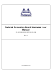
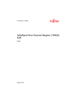
s
ie
og
hn
ol
ConnectXTM IB Dual Port InfiniBandAdapter
Cards User’s Manual
Te
c
P/N: MHEH28-XSC, MHEH28-XTC, MHGH28-XSC, MHGH28-XTC,
MHGH29-XTC
M
el
la
no
x
Rev 0.11
Mellanox T echnologies Confidential
2
© Copyright 2007. Mellanox Technologies, Inc. All Rights Reserved.
Mellanox Technologies, InfiniHost, and ConnectX are registered trademarks for Mellanox Technologies, Inc.
All other marks and names mentioned herein may be trademarks of their respective companies.
ConnectX IBDual Port InfiniBandAdapter Cards With PCI Express User’s Manual
s
Document Number: 2802 Mellanox Technologies, Inc.
2900 Stender Way
Santa Clara, CA 95054
U.S.A.
www.mellanox.com
og
ie
Tel: (408) 970-3400
Fax: (408) 970-3403
hn
ol
Mellanox Technologies Ltd.
PO Box 586 Hermon Building
Yokneam 20692
Israel
M
el
la
no
x
Te
c
Tel: +972-4-909-7200
Fax: +972-4-959-3245
Rev 0.11
Mellanox T echnologies Confidential
ConnectX InfiniBand Dual Port HCA Adapter Cards With PCI Express x8 User’s Manual
3
Table of Contents
Revision History
6
About this Manual
7
Chapter 1
Overview
8
1.1 Adapter Cards
1.2 Mellanox Part Numbering Legend
8
9
Chapter 2
HCA Card Installation
10
2.1 Hardware and Software Requirements
2.2 Installation Instructions
10
10
Chapter 4 Adapter Card Interfaces
ol
I/O Interfaces
I2C Compatible Interface
Power
Memory
VPDs
hn
4.1
4.2
4.3
4.4
4.5
Te
c
Chapter 5 Connectivity
12
12
12
12
12
13
13
14
14
14
15
21
22
22
22
25
25
26
27
x
Board Mechanical Drawing and Dimensions
EMC Certification Statements
MHEH28-XSC and MHEH28-XTC Specifications
MHGH28-XSC and MHGH28-XTC Specifications
MHGH29-XTC Specifications
no
AppendixA Specifications
A.1
A.2
A.3
A.4
A.5
ie
og
3.1 Driver Software
3.2 Updating HCA Card Firmware
3.3 Single HCA Card Firmware Update
3.4 HCA Card Firmware Update as Part of a Cluster Firmware Update
s
Chapter 3 Driver Software and Firmware
AppendixB Interface Connectors Pinout
la
B.1 I2C-compatible Connector Pinout
B.2 InfiniBand Connector Pinout
B.3 PCI Express x8 Connector Pinout
el
AppendixC Replacing a Tall Bracket with a Short Bracket on HCA Cards
M
C.1 Removing Tall Bracket
C.2 Placing a Kapton® Polyimide Label
C.3 Assembling Short Bracket
Mellanox T echnologies Confidential
27
27
28
29
29
31
33
Rev 0.11
4
List of Tables
Revision History Table
6
Table 2:
Documents List
7
Table 3:
HCA Cards
8
Table 4:
Mellanox HCA Cards Part Numbering Key
9
Table 5:
Hardware and Software Requirements
10
Table 6:
LEDs
14
Table 7:
Jumper Configuration
15
Table 8:
VPD Layout for MHEH28-XSC
15
Table 9:
VPD Layout for MHEH28-XTC
ie
s
Table 1:
og
Table 10: VPD Layout for MHGH28-XSC
Table 11: VPD Layout for MHGH28-XTC
ol
Table 12: VPD Layout for MHGH29-XTC
Table 14: Specifications for MHEH28-XSC/-XTC
Table 15: Specifications for MHGH28-XSC/-XTC
Te
c
Table 16: Specifications for MHGH29-XSC/-XTC
hn
Table 13: HCA Cards EMC Certification Status
16
17
18
19
22
25
25
26
Table 17: I2C-compatible Connector Pinout
27
Table 18:
28
M
el
la
no
x
Connector Pin To Port Signal Name
Rev 0.11
Mellanox T echnologies Confidential
ConnectX InfiniBand Dual Port HCA Adapter Cards With PCI Express x8 User’s Manual
5
List of Figures
MHGH28-XTC
8
Figure 2:
Port Numbering
13
Figure 3:
Physical and Logical Link Indications
14
Figure 4:
I2C Connector
14
Figure 5:
Schematic of the InfiniBand Adapter Card With CX4 Connectors
22
Figure 6:
I2C-compatible Connector
27
Figure 7:
ConnectX CX4 Copper Connector Pinout
27
Figure 8:
Tall Bracket of a Dual IB Port HCA Card
29
Figure 9:
Connector Retention Clip
ie
s
Figure 1:
og
Figure 10: Extracting Connector Clip
Figure 12: Rotate the Bracket to Detach it From the Card
Figure 13: Hold Kapton Label With Pincers
ol
Figure 11: Unscrew Bracket Screws
29
30
30
31
31
32
Figure 15: Ensure That Label is Well-attached
32
Te
c
Figure 16: HCA Card Ready for Short Bracket
hn
Figure 14: Place Label on Print Side With Label’s and Card’s Holes Aligned
33
33
Figure 18: Attach Bracket onto Card using Screws
34
Figure 19: Sliding Connector Clip Evenly
34
Figure 20: Fix Clip Hooks into Place Using Screwdriver
35
Figure 21: Assembled Short Bracket View
35
Figure 22: Assembled Short Bracket View
35
Figure 23: Print Side View After Short Bracket Assembly With Kapton Label
36
M
el
la
no
x
Figure 17: Place Short Bracket onto Card
Mellanox T echnologies Confidential
Rev 0.11
6
Revision History
This document was printed on 2/4/08.
Table 1 - Revision History Table
Rev
May 2007
0.10
Comments/Changes
Preliminary first revision
M
el
la
no
x
Te
c
hn
ol
og
ie
s
Date
Rev 0.11
Mellanox T echnologies Confidential
ConnectX InfiniBand Dual Port HCA Adapter Cards With PCI Express x8 User’s Manual
7
About this Manual
This User’s Manual describes Mellanox Technologies ConnectXTM IB 10GBase-CX4 Ethernet PCI Express HCA
cards. It provides details as to the interfaces of the card, specifications, required software and firmware for operating
the card, and relevant documentation.
s
Intended Audience
ie
This manual is intended for the installer and user of these cards.
og
The manual assumes basic familiarity with Infiniband™ networks.
ol
Related Documentation
hn
Table 2 - Documents List
Reference describing the interface used by developers to write a device
driver.
ConnectXTM IB MT25208 Hardware Reference Manual
Document no. 2715HM
x
Mellanox Firmware Tools (MFT) User’s Manual
Document no. 2204UG
Te
c
ConnectXTM IB Programmer’s Reference Manual
Document no. 2623PM
Reference for hardware engineers responsible for designing systems and
boards incorporating ConnectXTM IB components.
User’s Manual describing the set of MFT firmware management toolsfor a single InfiniBand node. See http://www.mellanox.com under
‘Firmware’ downloads.
User’s Manual describing the utilities included in the IBADM tools
package for system administration of an InfiniBand cluster. See
http://www.mellanox.com under ‘Management Tools’.
IB Specifications Release 1.0.a
Infiniband Architecture Specifications
la
Industry Standard PCI Express 2.0 Card Electromechanical Specification, Rev 1.3.
M
el
PCI Express 2.0 Specifications
no
InfiniBand Administration (IBADM) Package User’s Manual
Document no. 2130UM
Online Resources
•
•
•
Mellanox Technologies Web pages: http://www.mellanox.com
Mellanox Technologies Firmware download Web page: http://www.mellanox.com/ under Firmware downloads
Mellanox Technologies Document Distribution System (DDS): http://docs.mellanox.com (requires a customer
login account)
Document Conventions
When discussing memory sizes, MB and MBytes are used in this document to mean size in mega bytes. The use of
Mb or Mbits (small b) indicates size in mega bits.
Mellanox T echnologies Confidential
Rev 0.11
8
1 Overview
This document is a User’s Manual for Mellanox Technologies host channel adapter (HCA) Cards based on the
MT25408 ConnectXTM IB integrated circuit device. The cards described in this manual have the following main features:
s
ie
og
•
•
•
IBTA v1.2 compliant
Two 4X InfiniBand copper ports for connecting InfiniBand traffic (4X IB connectors)
Two 10GBASE-CX4 copper ports for connecting Ethernet traffic
PCI Express 2.0 (1.1 compatible) through an x8 edge connector up to 5GT/s
‘Media detect circuit’ with powered connectors supporting the use of active cables and external PHY fiber solutions
EU Restriction of Hazardous Substances (RoHS) compliant
The cards differ in::IB10Gb/s (SDR) or 20Gb/s (DDR) Bracket height: short or tall
PCI Express 2.0 with SerDes speed: 2.5 GT/s or 5.0 GT/s
ol
•
•
•
•
•
hn
1.1 Adapter Cards
Table 3 - HCA Cards
IB SDR
/ DDR
MHEH28-XSC
2.5 GT/s
SDR
MHEH28-XTC
2.5 GT/s
MHGH28-XSC
2.5 GT/s
MHGH28-XTC
2.5 GT/s
Short /
Tall
Bracket
la
el
M
MHGH29-XTC
5.0 GT/s
DDR
RoHS
Complian
ce
x
PCI
Express
SERDES
Speed
Short
no
Ordering Part
Number (OPN)
Te
c
Table 3 lists the InfiniBand HCA cards described in this manual.
HCA IC
Part Number
RoHS-R5
(with
exemption)
MT25408A0-FCCSI
RoHS-R5
(with
exemption)
MT25408A0-FCCDI
(1)
Figure 1: MHGH28-XTC
Tall
Short
Tall
DDR
Tall
MT25408A0-FCCGI
1. The HCA cards have a similar form and fit. The main visible difference is in the bracket height.
Rev 0.11
HCA Card Photo
Mellanox T echnologies Confidential
Short
Bracket
(-XSC)
Tall
Bracket
(-XTC)
ConnectX IBDual Port InfiniBand Adapter Cards With PCI Express x8 User’s Manual
9
1.2 Mellanox Part Numbering Legend
Table 4 describes the Mellanox Technologies adapter cards part numbering legend.
Table 4 - Mellanox HCA Cards Part Numbering Key
HCA Card OPN
MHTS#I-XBR
Field
Decoder
Mellanox
Technologies
H
Adapter Type
H = InfiniBand Host Channel Adapter, N = Ethernet Network Interface Card, S = Express
Module
T
Media
E = 10GBASE-CX4*, G = 10GBASE-CX4*, K = 10GBASE-SR (XFP), T = 10GBASE-T
* = with powered connector
S
Silicon
H = ConnectX
#
# ports
1 = 1, 2 = 2,
I
Host Interface
8 = PCIe x8, 9 = PCIe (SerDes @ 5.0 GT/s)
G
Generation
<blank> = Initial product generation
-
Separator
X
Memory Size
X = MemFree
B
Bracket
S = Short, T = Tall, N = None
R
RoHS
<blank> = non RoHS, C = RoHS w/ Exemption, R = RoHS Lead-Free
Te
c
hn
ol
og
ie
s
M
el
la
field M = M to indicate a Mellanox Technologies product,
field H = H to indicate an InfiniBand Adapter Card,
field T = G to indicate Cu DDR,
field S = H to indicate the ConnectX family,
field # = 2 to indicate two ports,
field I = 8 to indicate PCI Express 2.0 x8 running at 2.5GT/s,
field X = X to indicate no on-board memory,
field B = S to indicate a short bracket, and
field R = C to indicate RoHS R5 (w/ Exemptions) compliance
M
•
•
•
•
•
•
•
•
•
no
x
For example, the part number MHGH28-XSC describes Mellanox Technologies’ ConnectX™ IB HCA card with
dual CX4 ports, a PCIe2.0 x8 2.5GT/s interface, no on-board memory (mem-free), a short PCI bracket, and RoHS R5
compliance. Using the legend,
Mellanox T echnologies Confidential
Rev 0.11
10
2 HCA Card Installation
2.1 Hardware and Software Requirements
Before installing the HCA Adapter card, please make sure that the system meets the hardware and software requirements listed in Table 5.
Table 5 - Hardware and Software Requirements
PCI Express x8 slot or x4 slot with x8 connector PCI Express x8 or x16 slots
Software
Operating
Systems/Distributions
•
•
For Windows see WinIB ReadMe at https://docs.mellanox.com/dm/WinIB/ReadMe.html
For Linux see OpenFabrics Enterprise Distribution (OFED) software package available via the OpenFabrics Web site http://www.openfabrics.org
og
Hardware
s
Description
ie
Requirement
ol
•
hn
2.2 Installation Instructions
Read all installation instructions before connecting the equipment to the power source.
Over-temperature
no
x
Te
c
2.2.1 Safety Warnings
el
la
The HCA Adapter cardshould not be operated in an area with an ambient temperature exceeding the maximum
recommended temperature of 55°C. Moreover, it requires an airflow velocity of 200LFM (linear feet per minute)
at this maximum ambient temperature.
M
During Lightning
During periods of lightning activity, do not work on the equipment or connect or disconnect cables.
Copper InfiniBand Cable Connecting/Disconnecting
Copper InfiniB cables are heavy and not very flexible. As such they should be carefully attached to or detached
from the connectors. Refer to the cable manufacturer for special warnings/instructions.
Rev 0.11
Mellanox T echnologies Confidential
ConnectX IBDual Port InfiniBand Adapter Cards With PCI Express x8 User’s Manual
11
Equipment Disposal
Disposal of this equipment should be in accordance to all national laws and regulations.
2.2.2 Installation Instructions
M
el
la
no
x
Te
c
hn
ol
og
ie
s
The adapter cards listed in Table 3 on page 8 are standard PCI Express x8 cards each with a standard x8 edge connector. Please consult the host machine documentation for instructions on how to install a PCI Express card.
Mellanox T echnologies Confidential
Rev 0.11
12
3 Driver Software and Firmware
3.1 Driver Software
For Linux, download and install the latest OpenFabrics Enterprise Distribution (OFED) software package available
via the OpenFabrics Web site at http://www.openfabrics.org. Follow the installation instructions included in the
download package.
ie
s
For Windows, download the appropriate software from https://docs.mellanox.com/dm/WinIB/ReadMe.html.
3.2 Updating HCA Card Firmware
og
Each HCA card is shipped with the latest version of qualified firmware at the time of manufacturing. Firmware is
updated occasionally, and the most recent firmware can be obtained from http://www.mellanox.com through the
‘Firmware’ downloads link. HCA InfiniBand cluster firmware update
3.3 Single HCA Card Firmware Update
hn
ol
•
Te
c
Firmware can be updated on the standalone single card using the flint tool of the Mellanox Firmware Tools (MFT)
package. This package is available for download, along with its user’s manual, from the single HCA card firmware
update page. See http://www.mellanox.com under ‘Firmware’ downloads.
no
x
A firmware binaries table lists a binary file per HCA card. The file name of each such binary is composed by combining the firmware name, the firmware release version, and the card part number.
la
Note: Please contact your assigned Field Application Engineer if you cannot find the firmware binary for
your adapter card. This may happen if the product is not yet available for general distribution.
el
3.4 HCA Card Firmware Update as Part of a Cluster Firmware Update
M
If the HCA card is part of an InfiniBand cluster, its firmware can be updated as part of the entire cluster firmware
update1, using the ibfwmgr tool of the IB administration (IBADM) tools package. IBADM is available for download
from http://www.mellanox.com, through the Management Tools download link. Check the ‘Firmware’ downloads
link for cluster update instructions.
1. Currently, only the Linux distributions support updating firmware for an entire InfiniBand cluster.
Rev 0.11
Mellanox T echnologies Confidential
ConnectX IBDual Port InfiniBand Adapter Cards With PCI Express x8 User’s Manual
13
4 Adapter Card Interfaces
4.1 I/O Interfaces
Each HCA card includes the following interfaces:
s
Two 4X InfiniBand copper connectors
PCI Express x8 edge connector
I/O panel LEDs
I2C compatible connector (for debug)
ie
•
•
•
•
og
4.1.1 InfiniBand CX4 Interface
hn
ol
The ConnectXTM IB (MT25408) device is compliant with the InfiniBand Architecture Specification, Release 1.2. It
has two compliant 4X InfiniBand ports, 1 and 2, each having four Tx/Rx pairs of SerDes. Each of the HCA cards
(listed in Table 3 on page 8) based on this device provides access to these ports by means of two 4X InfiniBand connectors for external InfiniBand copper cables, also compliant with the IBTA specification 1.2. Connector 1 connects
to port 1 of the device, while connector 2 connects to port 2.
x
Te
c
Figure 2: Port Numbering
M
el
la
no
Port 1
Port 2
4.1.2 Each of the HCA cards is embedded with a ‘media detect circuit’ that supports active cables and external
InfiniBand fiber solutions to be connected to the InfiniBand port connectors. Fiber Solutions require the use of active
media converters.
Mellanox T echnologies Confidential
Rev 0.11
14
4.1.3 PCI Express Interface
The ConnectXTM IB HCA Adapter cards support the PCI Express 2.0 x8 interface, 1.1 compatible. The card can be
either a master initiating the PCI Express bus operations or a slave responding to PCI bus operations.
4.1.4 LED Assignment
s
The board has four LEDs located on the I/O panel - 2 LEDs per 4X port. The green LED, when lit, indicates that the
InfiniBand driver is running and a valid physical connection between nodes exists. The yellow LED when lit, indicates a valid data activity link, this is the logical link. The yellow LED illuminates when the InfiniBand network is
discovered over the physical link. A valid data activity link without data transfer is designated by a constant yellow
LED indication. A valid data activity link with data transfer is designated by a blinking yellow LED indication. If the
LEDs are not active, either the physical link or the logical link (or both) connections have not been established.
Port 1
Physical Link - Green
Figure 3: Physical and Logical Link Indications
Port 2
Physical Link - Green
Port 1
hn
Data Activity - Yellow
Blinking indicates Data Transfer
Constant on indicates no Data Transfer
og
LED Name
ol
Port Number
ie
Table 6 - LEDs
Te
c
Data Activity - Yellow
Blinking indicates Data Transfer
Constant on indicates no Data Transfer
Port 2
Note: The short bracket has the same port and LED footprint as the tall bracket.
no
x
4.2 I2C Compatible Interface
Figure 3: I2C Connector
M
el
la
A three-pin header on the HCA card is provided as the I2C compatible interface.See Figure 4 on page 22 for the location on the board.
4.3 Power
All adapter cards receive power from the PCI Express Edge connector. All other required power voltages are generated by on-board switch mode regulators. For power consumption see Specifications starting on page 22.
4.4 Memory
The HCA adapter cards support multiple memory devices through the PCI Express, Flash, and I2C-compatible interfaces.
Rev 0.11
Mellanox T echnologies Confidential
ConnectX IBDual Port InfiniBand Adapter Cards With PCI Express x8 User’s Manual
15
4.4.1 System Memory
Each of the HCA adapter cards utilizes the PCI Express interface to store and access IB fabric connection information
and packet date on the system memory.
4.4.2 Flash
Each of theHCA adapter cards includes one 2MB SPI Flash device (P/N M25P16-VME6G by ST Microelectronics)
accessible via the Flash interface of the MT25408 ConnectX IB device.
There is a jumper on each adapter card that indicates to the device whether an on-board Flash device exists (or is to be
used). Table 7 provides information on this jumper. See Figure 4 on page 22 for the jumper location.
Comments
connection open – Flash present
connection shorted – Flash not present
connection open
– Flash present
Header 1x2
hn
ol
Flash present/ not present
ie
Card Default
Configuration
Option
og
Description
s
Table 7 - Jumper Configuration
4.4.3 EEPROM
Te
c
Each board incorporates an EEPROM that is accessible through the I2C-compatible interface. The EEPROM is used
for storing the Vital Product Data (VPD). The VPD format adheres to the PCI Local Bus specification rev 2.3 VPD
definition (see “VPDs” on page 15). The EEPROM capacity is 512 bytes.
The PCI VPD (Vital Product Data) layout for each of the described Mellanox Technologies ConnectXTM IB
HCA Adapter cardscomply with the format defined in the PCI 2.3 “A1” was used as the HCA card (PCB) revision. Later revisions of the HCA card will have the same format.
no
•
x
4.5 VPDs
1
2
3
Value
Large Resource Type ID String Tag (0x02)
0x82
el
0
Item
M
Offset (Decimal)
la
Table 8 - VPD Layout for MHEH28-XSC
Length [7:0] LSB
Format
0x9
Length [15:8] MSB
0x0
Data
Eagle SDR
STR
12
Large Resource Type VPD-R Tag (0x10)
0x90
13
Length [7:0] LSB
0x4F
14
Length [15:8] MSB
0x00
15
VPD Keyword
PN
17
Length
0x15
18
PN
MHEH28-XSC
%STR_SPC
VPD Keyword
EC
STR
Length
0x2
39
41
Description
Mellanox T echnologies Confidential
STR
Add in Card Part Number
Engineering Change
Level of the card (rev)
Rev 0.11
16
Table 8 - VPD Layout for MHEH28-XSC (Continued)
Item
Value
Format
Description
42
Revision
A1
%STR
PCB revision
44
VPD Keyword
SN
STR
Serial Number
46
Length
0x18
%STR_SPC
“00..00XXXX..XX”
STR
Misc. Information
47
Serial Number
71
VPD Keyword
73
Length
0x10
74
Data
PCIe x8
STR_SPC
90
VPD Keyword
RV
STR
92
Length
0x1
V0
95
Length [7:0] LSB
0x9E
96
Length [15:8] MSB
0x00
97
VPD Keyword
V1
99
Length
0x6
100
Data
N/A
106
VPD Keyword
108
Length
109
Data
STR
YA
EFI Driver version
STR_SPC
STR
Asset Tag
STR_SPC
“N/A”
STR
Remaining read/write
area
STR_ZERO
Reserved (0x00)
0x20
Te
c
N/A
VPD Keyword
141
%CS0
ie
0x91
og
0,92
Large Resource Type VPD-W Tag (0x11)
ol
Data
94
hn
93
s
Offset (Decimal)
(Continued)
RW
Length
144
Data
0x6F
255
Small Resource Type END Tag (0x11)
0x78
no
x
143
la
Note: “A1” was used as the HCA card (PCB) revision. Later revisions of the HCA card will have the same
format.
0
1
Rev 0.11
Item
Value
Large Resource Type ID String Tag (0x02)
0x82
Length [7:0] LSB
0x9
M
Offset (Decimal)
el
Table 9 - VPD Layout for MHEH28-XTC
2
Length [15:8] MSB
0x0
3
Data
Eagle SDR
12
Large Resource Type VPD-R Tag (0x10)
0x90
13
Length [7:0] LSB
0x4F
14
Length [15:8] MSB
0x00
15
VPD Keyword
PN
17
Length
0x15
18
PN
MHEH28-XTC
Mellanox T echnologies Confidential
Format
Description
STR
STR
%STR_SPC
Add in Card Part Number
ConnectX IBDual Port InfiniBand Adapter Cards With PCI Express x8 User’s Manual
17
Table 9 - VPD Layout for MHEH28-XTC (Continued)
Offset (Decimal)
(Continued)
39
41
Item
Value
Format
Description
VPD Keyword
EC
STR
Engineering Change
Level of the card (rev)
Length
0x2
Revision
A1
%STR
PCB revision
44
VPD Keyword
SN
STR
Serial Number
46
Length
0x18
47
Serial Number
%STR_SPC
“00..00XXXX..XX”
71
VPD Keyword
V0
STR
Misc. Information
73
Length
0x10
74
Data
PCIe x8
STR_SPC
90
VPD Keyword
RV
STR
92
Length
0x1
93
Data
0,92
94
Large Resource Type VPD-W Tag (0x11)
0x91
95
Length [7:0] LSB
0x9E
96
Length [15:8] MSB
0x00
97
VPD Keyword
V1
Data
106
VPD Keyword
108
Length
109
x
no
Length
144
ie
og
N/A
STR_SPC
YA
STR
Asset Tag
N/A
STR_SPC
“N/A”
RW
STR
Remaining read/write
area
STR_ZERO
Reserved (0x00)
0x6F
Data
Small Resource Type END Tag (0x11)
0x78
la
255
EFI Driver version
0x20
Data
143
STR
0x6
VPD Keyword
141
ol
hn
Length
%CS0
Te
c
99
100
s
42
M
el
Note: “A1” was used as the HCA card (PCB) revision. Later revisions of the HCA card will have the same
format.
Table 10 - VPD Layout for MHGH28-XSC
Offset (Decimal)
Item
Value
0
Large Resource Type ID String Tag (0x02)
0x82
1
Length [7:0] LSB
0x9
2
Length [15:8] MSB
0x0
3
Data
Eagle SDR
12
Large Resource Type VPD-R Tag (0x10)
0x90
13
Length [7:0] LSB
0x4F
14
Length [15:8] MSB
0x00
15
VPD Keyword
PN
Mellanox T echnologies Confidential
Format
Description
STR
STR
Add in Card Part Number
Rev 0.11
18
Table 10 - VPD Layout for MHGH28-XSC (Continued)
Offset (Decimal)
(Continued)
Item
Value
17
Length
0x15
18
39
41
Format
PN
MHGH28-XSC
%STR_SPC
VPD Keyword
EC
STR
Length
0x2
Description
Engineering Change
Level of the card (rev)
Revision
A1
%STR
PCB revision
44
VPD Keyword
SN
STR
Serial Number
46
Length
0x18
47
Serial Number
%STR_SPC
“00..00XXXX..XX”
71
VPD Keyword
V0
73
Length
0x10
74
Data
PCIe x8
90
VPD Keyword
RV
92
Length
0x1
93
Data
0,92
94
Large Resource Type VPD-W Tag (0x11)
0x91
95
Length [7:0] LSB
0x9E
96
Length [15:8] MSB
97
VPD Keyword
Data
106
VPD Keyword
108
Length
Data
143
ie
og
N/A
STR_SPC
EFI Driver version
YA
STR
Asset Tag
0x20
N/A
STR_SPC
“N/A”
VPD Keyword
RW
STR
Remaining read/write
area
Length
0x6F
STR_ZERO
Reserved (0x00)
Data
Small Resource Type END Tag (0x11)
0x78
M
el
255
STR
0x6
la
144
%CS0
ol
V1
no
141
STR
0x00
x
109
Misc. Information
STR_SPC
hn
Length
STR
Te
c
99
100
s
42
Note: “A1” was used as the HCA card (PCB) revision. Later revisions of the HCA card will have the same
format.
Table 11 - VPD Layout for MHGH28-XTC
Offset (Decimal)
Item
Value
0
Large Resource Type ID String Tag (0x02)
0x82
Rev 0.11
1
Length [7:0] LSB
0x9
2
Length [15:8] MSB
0x0
3
Data
Eagle SDR
12
Large Resource Type VPD-R Tag (0x10)
0x90
13
Length [7:0] LSB
0x4F
Mellanox T echnologies Confidential
Format
STR
Description
ConnectX IBDual Port InfiniBand Adapter Cards With PCI Express x8 User’s Manual
19
Table 11 - VPD Layout for MHGH28-XTC (Continued)
Offset (Decimal)
(Continued)
Item
Value
14
Length [15:8] MSB
0x00
15
VPD Keyword
PN
17
Length
0x15
18
39
Format
Description
STR
Add in Card Part Number
PN
MHGH28-XTC
%STR_SPC
VPD Keyword
EC
STR
Length
0x2
41
Engineering Change
Level of the card (rev)
Revision
A1
%STR
PCB revision
44
VPD Keyword
SN
STR
Serial Number
46
Length
0x18
47
Serial Number
71
VPD Keyword
V0
73
Length
0x10
74
Data
PCIe x8
90
VPD Keyword
RV
92
Length
0x1
93
Data
0,92
94
Large Resource Type VPD-W Tag (0x11)
95
Length [7:0] LSB
96
Length [15:8] MSB
97
VPD Keyword
Length
Data
106
108
143
ie
og
hn
ol
STR
%CS0
0x00
V1
STR
EFI Driver version
0x6
STR_SPC
VPD Keyword
YA
STR
Length
0x20
x
N/A
Asset Tag
Data
N/A
STR_SPC
“N/A”
VPD Keyword
RW
STR
Remaining read/write
area
0x6F
STR_ZERO
Reserved (0x00)
Length
Data
Small Resource Type END Tag (0x11)
0x78
M
255
Misc. Information
0x91
el
144
STR
0x9E
no
141
“00..00XXXX..XX”
la
109
%STR_SPC
STR_SPC
Te
c
99
100
s
42
Table 12 - VPD Layout for MHGH29-XTC
Offset
(Decimal)
Item
Value
0
Large Resource Type ID String Tag (0x02)
0x82
1
Length [7:0] LSB
0x9
2
Length [15:8] MSB
0x0
3
Data
Eagle DDR
12
Large Resource Type VPD-R Tag (0x10)
0x90
Mellanox T echnologies Confidential
Format
Description
STR
Rev 0.11
20
Table 12 - VPD Layout for MHGH29-XTC (Continued)
Offset
(Decimal)
Item
Value
13
Length [7:0] LSB
0x4F
14
Length [15:8] MSB
0x00
15
VPD Keyword
PN
17
Length
0x15
18
PN
MHGH29XSC
%STR_SPC
39
VPD Keyword
EC
STR
41
Length
0x2
Format
Description
STR
Add in Card Part Number
A1
%STR
VPD Keyword
SN
STR
46
Length
0x18
47
Serial Number
71
VPD Keyword
V0
73
Length
0x10
74
Data
PCIe Gen2
x8
90
VPD Keyword
RV
92
Length
0x1
97
VPD Keyword
99
Length
og
ol
Misc. Information
STR_SPC
STR
%CS0
0x91
0x9E
0x00
V1
x
Length [7:0] LSB
Length [15:8] MSB
0,92
“00..00XXXX..XX”
hn
Large Resource Type VPD-W Tag (0x11)
STR
Te
c
Data
94
96
Serial Number
%STR_SPC
93
95
PCB revision
s
Revision
44
ie
42
Engineering Change Level of the
card (rev)
STR
EFI Driver version
0x6
Data
N/A
STR_SPC
106
VPD Keyword
YA
STR
Asset Tag
108
Length
0x20
N/A
STR_SPC
“N/A”
STR
Remaining read/write area
STR_ZERO
Reserved (0x00)
la
no
100
Data
141
VPD Keyword
RW
143
el
109
0x6F
255
Rev 0.11
M
144
Length
Data
Small Resource Type END Tag (0x11)
0x78
Mellanox T echnologies Confidential
ConnectX IBDual Port InfiniBand Adapter Cards With PCI Express x8 User’s Manual
21
5 Connectivity
M
el
la
no
x
Te
c
hn
ol
og
ie
s
This adapter card can be connected to switches and routers using 20 + meters of passive copper CX4 cables for SDR
Adapter cards, and 10 + meters of passive copper CX4 cables for DDR Adapter cards. These lengths are greatly
increased with active copper CX4 cables or with fiber cables with external adapters.
Mellanox T echnologies Confidential
Rev 0.11
22
Appendix A: Specifications
A.1 Board Mechanical Drawing and Dimensions
All the HCA cards covered in this User’s Manual have the same mechanical drawing and share the same dimensions
as depicted in Figure 4.
Te
c
hn
ol
og
ie
Figure 4: Schematic of the InfiniBand Adapter Card With CX4 Connectors
s
Note: All dimensions are in millimeters.
no
x
J5 I2C Connector
M
el
la
J6 Flash Jumper
A.2 EMC Certification Statements
Table 13 lists the approved EMC certification status per HCA card in different regions of the world. .
Table 13 - HCA Cards EMC Certification Status
Rev 0.11
HCA Card P/N
FCC Class (USA)
EN Class (Europe)
ICES Class (Canada)
MHEH28-XSC
A
A
A
MHEH28-XTC
A
A
A
MHGH28-XSC
A
A
A
Mellanox T echnologies Confidential
ConnectX IBDual Port InfiniBand Adapter Cards With PCI Express x8 User’s Manual
23
Table 13 - HCA Cards EMC Certification Status
HCA Card P/N
FCC Class (USA)
EN Class (Europe)
ICES Class (Canada)
MHGH28-XTC
A
A
A
MHGH29-XTC
TBD
TBD
TBD
A.2.1 FCC
A.2.2 Statements (USA)
Class A Statements:
ie
s
§ 15.21
og
Statement
ol
Warning! Changes or modifications to this equipment not expressly approved by the party responsible for compliance (Mellanox Technologies) could void the user's authority to operate the equipment.
hn
§15.105(a)
Te
c
Statement
no
x
NOTE: This equipment has been tested and found to comply with the limits for a Class A digital device, pursuant to
Part 15 of the FCC Rules. These limits are designed to provide reasonable protection against harmful interference
when the equipment is operated in a commercial environment. This equipment generates, uses, and can radiate radio
frequency energy and, if not installed and used in accordance with the instruction manual, may cause harmful interference to radio communications. Operation of this equipment in a residential area is likely to cause harmful interference in which case the user will be required to correct the interference at his own expense.
la
A.2.3 EN Statements (Europe)
EN55022 Class A Statement: RF Emissions Control
el
Warning
M
This is a class A product. In a domestic environment this product may cause radio
interference in which case the user may be required to take adequate measures.
A.2.4 ICES Statements (Canada)
Class A Statement:
“This Class A digital apparatus complies with Canadian ICES-003.
Cet appareil numérique de la classe A est conforme à la norme NMB-003 du Canada.”
Mellanox T echnologies Confidential
Rev 0.11
24
A.2.5 VCCI Statements (Japan)
Class A Statement:
ie
s
(Translation - "This is a Class A product based on the standard of the Voluntary Control Council for Interference by
Information Technology Equipment (VCCI). If this equipment is used in a domestic environment, radio interference
may occur, in which case the user may be required to take corrective actions.")
og
A.2.6 MIC Statement (Republic of Korea)
hn
ol
Korea's "Regulation for Certification of Information and Communication Equipment," requires EMC testing and certification for many electronic products. Korean EMC certifications are issued by Radio Research Laboratory (RRL),
which is organized under the Ministry of Information and Communications (MIC). EMC testing includes electromagnetic emissions (EMI) and susceptibility (EMS). Certified equipment is labeled with the MIC mark and certification
number.
x
Te
c
Class A Statement:
no
Translation:
M
el
la
Class A Device: This device is registered for EMC requirements for industrial use. The seller or buyer should be
aware of this. If this type was sold or purchased by mistake, it should be replaced with a residential-use type.
Rev 0.11
Mellanox T echnologies Confidential
ConnectX IBDual Port InfiniBand Adapter Cards With PCI Express x8 User’s Manual
25
A.3 MHEH28-XSC and MHEH28-XTC Specifications
.
Table 14 - Specifications for MHEH28-XSC/-XTC
Physical
Power and Environmental
Size:
Air Flow:
4X 10Gb/s Connector:
2.54in. x 5.37in. (64.4mm x 136.47mm)
200LFM @55°C
InfiniBand (Copper, current rating: 0.5A
max) with active media adapter support
12V, 3.3V
11.01W
12.62W
0°C to 55°C
QoS:
RDMA Support:
Data Rate:
PCI Express
IBTA v1.2, Auto-Negotiation 10Gb/s,
2.5Gb/s
8 InfiniBand Virtual Lanes for each port
Yes, All Ports
Single
2.0 SERDES @ 2.5 GT/s
Safety:
MIC Certification
IEC/EN 60950-1:2001
ETSI EN 300 019-2-2
ie
InfiniBand:
s
Regulatory
og
Protocol Support
Voltage:
Typ. Power:
Maximum Power:
Temperature:
Environmental:
RoHS-R5
M
el
la
no
x
Te
c
hn
ol
RoHS:
IEC 60068-2- 64, 29, 32
Mellanox T echnologies Confidential
Rev 0.11
26
A.4 MHGH28-XSC and MHGH28-XTC Specifications
Table 15 - Specifications for MHGH28-XSC/-XTC
Physical
Power and Environmental
Size:
Air Flow:
4X 20Gb/s Connector:
2.54in. x 5.37in. (64.4mm x 136.47mm)
200LFM @55°C
InfiniBand (Copper, current rating: 0.5A
max) with active media adapter support
12V, 3.3V
11.48W
13.09W
0°C to 55°C
•
FCC 47 CFR part 15:2005, subpart B, class
A
ICES-003:2004 Issue 4, class A
VCCI V-3/2005.04, class A
2.0 SERDES @ 2.5 GT/s
EN 55022:1998+A1:2000+A2:2003 class
A, EN 61000-3-2:2000+A2:2005,
EN61000-3-3:1995+A1:2001, EN
55024:1998 + A1:2001+A2:2003 standards, harmonized under EMC Directive
89/336/EEC;
Safety:
Environmental:
no
x
Te
c
hn
ol
QoS:
RDMA Support:
Double Data Rate:
PCI Express
•EMC:
IBTA v1.2, Auto-Negotiation1 (20Gb/s,
5Gb/s) or (10Gb/s, 2.5Gb/s)
8 InfiniBand Virtual Lanes for each port
Yes, All Ports
og
InfiniBand:
s
Regulatory
ie
Protocol Support
Voltage:
Typ. Power:
Maximum Power:
Temperature:
RoHS:
MIC Certification
IEC/EN 60950-1:2001
ETSI EN 300 019-2-2
IEC 60068-2- 64, 29, 32
RoHS-R5
M
el
la
1. The auto-negotiation protocol is proprietary of Mellanox Technologies and compliant with the InfiniBand Architecture Specification,
Release 1.2.
Rev 0.11
Mellanox T echnologies Confidential
ConnectX IBDual Port InfiniBand Adapter Cards With PCI Express x8 User’s Manual
27
A.5 MHGH29-XTC Specifications
Table 16 - Specifications for MHGH29-XSC/-XTC
Physical
Power and Environmental
Size:
Air Flow:
4X 20Gb/s Connector:
2.54in. x 5.37in. (64.4mm x 136.47mm)
200LFM @55°C
InfiniBand (Copper, current rating: 0.5A
max) with active media adapter support
12V, 3.3V
12.6W
TBD W
0°C to 55°C
•
TBD
2.0 SERDES @ 5.0 GT/s
hn
ol
QoS:
RDMA Support:
Double Data Rate:
PCI Express
•EMC:
IBTA v1.2, Auto-Negotiation1 (20Gb/s,
5Gb/s) or (10Gb/s, 2.5Gb/s)
8 InfiniBand Virtual Lanes for each port
Yes, All Ports
og
InfiniBand:
s
Regulatory
ie
Protocol Support
Voltage:
Typ. Power:
Maximum Power:
Temperature:
Te
c
Safety:
Environmental:
RoHS:
M
el
la
no
x
1. The auto-negotiation protocol is proprietary of Mellanox Technologies and compliant with the InfiniBand Architecture Specification,
Release 1.2.
Mellanox T echnologies Confidential
Rev 0.11
ConnectX IBDual Port InfiniBand Adapter Cards With PCI Express x8 User’s Manual
27
Appendix B: Interface Connectors Pinout
B.1 I2C-compatible Connector Pinout
Figure 5: I2C-compatible Connector
1
SPSDA
2
SPSCL
3
GND
4
NC
ol
hn
4
3
2
1
ie
HCA Signal Name
og
Connector Pin Number
5 1 2 3 4
5
s
Table 1 - I2C-compatible Connector Pinout
NC
Te
c
5
B.2 InfiniBand Connector Pinout
Figure 6: ConnectX CX4 Copper Connector Pinout
no
x
J2
IBtxIp(3)
S9
IBtxOn(3)
IBtxIn(3)
IBtxOp(2)
IBtxIp(2)
IBtxOn(2)
IBtxIn(2)
IBtxOp(1)
IBtxIp(1)
IBtxOn(1)
IBtxIn(1)
IBtxOp(0)
IBtxIp(0)
IBtxOn(0)
IBtxIn(0)
S14
S13
S16
S15
S8
S5
S6
S3
S4
S1
S2
H1
G1
G2
G3
G4
G5
G6
G7
G8
G9
H2
el
S11
S7
GND
GND
GND
GND
GND
GND
GND
GND
GND
GND
GND
IBtxOp(3)
la
S10
S12
M
Conn 1X
Mellanox T echnologies Confidential
Rev 0.11
28
Connector Pin
Name
IB Port A Signal
Name
IB Port B Signal
Name
S1
IBtxIp(0)
Rx_A1
Rx_B1
S2
IBtxIn(0)
Rx_A0
Rx_B0
S3
IBtxIp(1)
Rx_A3
Rx_B3
S4
IBtxIn(1)
Rx_A2
Rx_B2
S5
IBtxIp(2)
Rx_A5
Rx_B5
S6
IBtxIn(2)
Rx_A4
Rx_B4
S7
IBtxIp(3)
Rx_A7
Rx_B7
S8
IBtxIn(3)
Rx_A6
Rx_B6
S9
IBtxOn(3)
Tx_A6
S10
IBtxOp(3)
Tx_A7
S11
IBtxOn(2)
Tx_A4
S12
IBtxOp(2)
S13
IBtxOn(1)
S14
IBtxOp(1)
Tx_A3
Tx_B3
S15
IBtxOn(0)
Tx_A0
Tx_B0
S16
IBtxOp(0)
Tx_A1
Tx_B1
G1-G6, G9, H1-H2
Signal Ground
GND
GND
Sense-3.3V
SENSE_P1
SENSE_P2
Vcc
MC_POWER_P1
MC_POWER_P2
G8
og
Tx_B6
ol
Tx_B7
hn
Tx_B4
Tx_A5
Tx_B5
Tx_A2
Tx_B2
Te
c
x
no
G71
ie
Connector Pin
Number
s
Table 2 - Connector Pin To Port Signal Name
t
M
el
la
1. The Sense-3.3V signal is used to enable the Vcc power supply pin (G8)
used to provide power to the active media adapter.
B.3 PCI Express x8 Connector Pinout
These cards use a standard PCI Express x8 edge connector and the PCI Express x8 standard pinout according to the
PCI Express 2.0 specification.
Rev 0.11
Mellanox T echnologies Confidential
ConnectX IB Dual Port InfiniBand Adapter Cards With PCI Express x8 User’s Manual
29
Appendix C: Replacing a Tall Bracket with a
Short Bracket on HCA Cards
This appendix provides instructions on how to remove a tall bracket of a Mellanox Technologies HCA card and
replace it with a short one. It includes the following sections:
s
“Removing Tall Bracket”
“Placing a Kapton® Polyimide Label”
“Assembling Short Bracket”
ie
•
•
•
og
Figure 7 shows the bracket-side view of a dual-port HCA card.
Te
c
hn
ol
Figure 7: Tall Bracket of a Dual IB Port HCA Card
no
x
C.1 Removing Tall Bracket
Step 1 - Remove connector clips Figure 8 shows a connector retention clip and the designated names of its secFigure 8: Connector Retention Clip
M
el
la
tions.
1.
2.
Using a small flat head screwdriver, gently push up one hook of a connector’s clip toward the connector’s top
side as shown in Figure 9 (a) on page 30.
Then push the other hook each of the two clip’s hook towards the connector’s top side - see Figure 9 (b). Finally,
pull the clip away from its center - see Figure 9 (c).
Mellanox T echnologies Confidential
Rev 0.11
30
ol
og
Repeat the above actions for the second connector’s clip.
Step 2 - Unscrew bracket screws
Unscrew both screws from the card using a torque screwdriver as shown in Figure 10.
hn
1.
(c) Pull Clip Away
ie
(b) Gently Push Other Hook of Clip
(a) Gently Push One Hook of Clip
3.
s
Figure 9: Extracting Connector Clip
M
el
la
no
x
Te
c
Figure 10: Unscrew Bracket Screws
Step 3 - Detach bracket
1.
2.
Grip the bracket as shown in Figure 11, placing your thumb on the LED component.
In a rotating move toward the component side of the card, slide the bracket out of the connectors (Figure 11 (c)).
3.
Gently hold your thumb on the LED component.
4.
At the same time extract the bracket as shown in Figure 11 c, (Make sure to protect the LED while extracting the
bracket).
Rev 0.11
Mellanox T echnologies Confidential
ConnectX IB Dual Port InfiniBand Adapter Cards With PCI Express x8 User’s Manual
31
Figure 11: Rotate the Bracket to Detach it From the Card
ie
s
(a) Card without Clips and Screws
hn
ol
og
(b) Grip the Card in preparation for Detachment
Te
c
(c) Rotate the bracket toward the Component Side.
C.2 Placing a Kapton® Polyimide Label
no
x
Prior to assembling the short bracket, you need to apply a Kapton® polyimide round label on the board’s Print Side.
Note: Check to see if the label is already installed as this label may have been installed at the factory.
la
Note: The label can be provided by Mellanox Technologies (P/N: MEC000821).
el
The following steps are instructions for placing the polyimide label:
Make sure your working area is ESD protected.
2.
Hold the label with light pincers. See Figure 12.
M
1.
Figure 12: Hold Kapton Label With Pincers
Mellanox T echnologies Confidential
Rev 0.11
32
3.
Gently place the label as shown in Figure 13. Make sure to align the center hole of the label with the drilled hole
in the board.
After placing the label, complete the process by (gently) sweeping your thumb on the label to assure the label is
well-attached onto board. See Figure 14.
ol
4.
og
ie
s
Figure 13: Place Label on Print Side With Label’s and Card’s Holes Aligned
el
la
no
x
Te
c
hn
Figure 14: Ensure That Label is Well-attached
M
See also Figure 22, “Print Side View After Short Bracket Assembly With Kapton Label,” on page 36.
Now your card is ready for a short bracket assembly.
Rev 0.11
Mellanox T echnologies Confidential
ConnectX IB Dual Port InfiniBand Adapter Cards With PCI Express x8 User’s Manual
33
C.3 Assembling Short Bracket
The short bracket can now be assembled onto the HCA card. See Figure 15.
ol
og
ie
s
Figure 15: HCA Card Ready for Short Bracket
hn
Step 1 - Place short bracket onto card 5. Gently place the bracket onto the card fitting the connectors through
the bracket connector holes. Make sure the LEDs are aligned into their intended bracket holes.Step 2 - Attach
LED Holes
M
el
la
no
x
Te
c
Figure 16: Place Short Bracket onto Card
Mellanox T echnologies Confidential
Rev 0.11
34
short bracket to cardInsert a screw along with a washer into each of the two holes on the card intended for
holding the bracket. Use a torque screwdriver to apply up to 2 lbs-in torque on each screw.
ol
og
ie
s
Figure 17: Attach Bracket onto Card using Screws
Step 3 - Install Connector Clips 1.Gently push one clip onto the connector. Make sure to slide both clip hooks
hn
(sides) around the connector evenly as shown in Figure 18.
M
el
la
no
x
Te
c
Figure 18: Sliding Connector Clip Evenly
Rev 0.11
Mellanox T echnologies Confidential
ConnectX IB Dual Port InfiniBand Adapter Cards With PCI Express x8 User’s Manual
2.
35
Use a small flat head screwdriver to gently slide the clip's hook towards the connector's base side as shown in
Figure 19.
ol
Repeat this step for the second clip. See Figure 21 for the assembled short bracket (side) view, and Figure 22 for
the Print Side view showing the Kapton label.
x
Te
c
hn
Figure 20: Assembled Short Bracket View
el
la
no
Figure 21: Assembled Short Bracket View
M
3.
og
ie
s
Figure 19: Fix Clip Hooks into Place Using Screwdriver
Mellanox T echnologies Confidential
Rev 0.11
36
M
el
la
no
x
Te
c
hn
ol
og
ie
s
Figure 22: Print Side View After Short Bracket Assembly With Kapton Label
Rev 0.11
Mellanox T echnologies Confidential