1
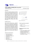
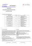
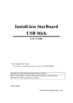
VHF Wireless Guitar System (VGW1 – 171.848EU, 171.848UK) User Manual Features: Sleek, ergonomic design Auto-mute on signal drop Wide frequency response Introduction: Thank you for choosing the Chord VHF-series wireless system. This professional wireless set provides an instrument VHF radio system for freedom of movement without loss of audio quality. Please read this manual before using this equipment in order to avoid damage through incorrect operation and to get the best performance from your purchase. Contents: Please take care when unpacking this product. Inspect for any damage and ensure you have the following components… VHF wireless receiver Mains power adapter 3.5mm to 6.3mm instrument jack lead 6.3mm mono jack lead 9V battery, PP3 Warning: To prevent the risk of fire or electric shock, do not expose any of the components to rain or moisture. If liquids are spilled on any component, stop using immediately, allow unit to dry out and have checked by qualified personnel before further use. Avoid impact or heavy vibration to any of the components. No user serviceable parts inside transmitter or receiver - refer servicing to qualified service personnel. Safety Ensure that the correct adapter is used with adequate current rating and that the mains voltage is as stated on the adapter. Avoid ingress of water or particles into the transmitter(s) or receiver Use alkaline or NiMH batteries in the transmitter(s) and remove if unused for long periods. Observe the correct polarity when replacing batteries Placement Keep all components out of direct sunlight and away from heat sources. Do not place heavy objects on top of the receiver or transmitter(s) If rack-mounting, secure the receiver to a 1U rack tray and do not place heavy equipment above the receiver. Keep the transmitter(s) and receiver away from damp or dusty environments. Cleaning Use a soft cloth with a neutral detergent to clean the body of the microphone/transmitter and receiver. Lightly damp sterile wipes may be used on the microphone grille for hygiene purposes To avoid damage, do not use solvents to clean the components Beltpack Transmitter 1. GAIN ADJUST rotary control 2. Slide switch and LED 3. MIC input (3.5mm jack) Receiver Rear Panel 1. 2. 3. 4. Antennae Power adapter input Unbalanced 6.3mm jack output Balanced XLR output 1. 2. 3. 4. 5. 6. Power ON/OFF switch Channel A volume control Channel A indicator LED Power indicator LED Channel B indicator LED Channel B volume control Receiver Front Panel Operation To begin, insert batteries into the transmitter. Slide the front half of the beltpack upwards just enough to reveal the battery compartment and position the supplied 9V battery inside (ensure + and - are the correct way round) and then slide the beltpack case together as before. Position the receiver within the best available line of sight to the transmitter(s) and connect the DC jack of the supplied power adapter to the receiver and the plug-top to the mains outlet. Extend both antennae fully upwards and outwards slightly and switch the power on. Turn the output level down on the receiver. Connect the jack or XLR (optional) lead to the receiver’s audio output connector, turn down the volume of the guitar amplifier (or effect unit) that the signal will be fed into and then connect the jack or XLR to the guitar amplifier. Move the slide switch on the beltpack transmitter to the first notch (MUTE) – the LED should light momentarily (continuous dim LED indicates low battery). Move on another notch (ON) and gradually increase the output level on the receiver, then increase the volume on the guitar amplifier until the sound from the guitar can be heard through the amp (ensuring guitar volume controls are turned up) If the wireless system is not to be used for more than a few seconds, it is preferable to slide the transmitter switch to the “OFF” position, which mutes and deactivates the radio signal and powers down the transmitter. Be sure to turn down the volume of the guitar amplifier and then switch off the receiver. Unplug signal leads from the receiver and mixer or amplifier when moving or packing away. If the system is not to be used for long periods of time, remove the batteries from the transmitter and unplug the power adapter from the receiver and the mains outlet. Retracting the antennae can also help avoid damage when the system is not in use. SPECIFICATIONS Carrier type Frequency stability Maximum deviation Audio frequency response Signal to noise ratio Audio dynamic range T.H.D. Maximum range Operating temperature VHF 174.1MHz (UK or AU), 198.25MHz (EU) ±0.005% ±30kHz 40Hz – 20kHz >85dB >80dB ≤0.2% 50m -10ºC to +50ºC RECEIVER Power supply Audio outputs Controls Indicators Dimensions Weight 12Vdc 300mA (mains adapter supplied) XLR (balanced), Jack (unbalanced) Power On/Off, Output volume Power, Signal (RF) 43 x 213 x 180mm 340g BELTPACK TRANSMITTER Battery Switch Connector RF emission Dimensions Weight (without battery) 9Vdc, PP3 Power / Mute / On 6.3mm to 3.5mm mono jack lead (supplied) <10mW 105 x 60 x 30mm 77g Troubleshooting “POWER” LED does not light on receiver “POWER” LED is lit but no “SIGNAL” LED LEDs are lit but no sound from microphone Clean guitar output is very loud or distorted Microphone output is very low Ensure power adapter is connected to mains and working properly Ensure receiver is switched on Ensure transmitter is switched on Check that transmitter is not out of reception range Check that transmitter battery is good / charged Check if transmitter switch is in “MUTE” position Check that the guitar volume controls are turned up Make sure receiver is connected to amplifier Make sure that amplifier volume is turned up Ensure transmitter has a good / charged battery Check if there is another nearby transmitter with the same frequency Turn down GAIN ADJUST on beltpack transmitter Turn down VOLUME on receiver Turn up GAIN ADJUST on beltpack transmitter Turn up VOLUME on receiver Increase Gain on amplifier Turn up guitar volume controls Check transmitter battery Note: for further troubleshooting, refer equipment to qualified service personnel for testing © Chord 2011