1
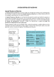
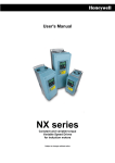
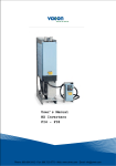
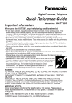
VACON NX QUICK HELP Start-up wizard The Start Up Wizard is activated when the power to the drive is turned on for the first time, or if the Start Up Wizard is activated from the System menu (P6.5.3) AND the power is turned OFF and back ON. The Start-up Wizard is a feature on the control keypad to facilitate the commissioning of the frequency converter. If selected active (default), the Start-up Wizard prompts the operator for the language and application of his/her choice plus for the values for a set of parameters common to all applications as well as for a set of application-dependent parameters. Always accept the value with the Enter button, scroll options or change values with the Browser buttons (up and down arrows). More information on the use of the control panel in Chapter 7 of the User's Manual. Startup wizard enter Press enter Additional parameter settings are prompted depending on the selected application. Basic application: I/O reference (P2.14) Language enter English Application Local/Remote control application: I/O reference A (P2.1.11) I/O reference B (P2.1.12) enter Standard Setup starts enter Press enter 0.00 Hz Multi-step speed application: I/O reference (P2.1.11) enter Multi-purpose control application: I/O reference (P2.1.11) Pump and fan control application: Act value 1 select (P2.2.1.9) PID controller ref (P2.1.11) No. of aux pumps (P2.9.1) Repeat setup? <No Nine parameter settings are prompted for each application: Min Frequency Standard application: I/O reference (P2.1.11) PID control application: Act value 1 selection (P2.2.9) PID controller ref (P2.1.11) Yes> Faults and fault codes Fault code 1 2 3 5 6 7 8 9 10 11 12 13 14 15 16 17 18 22 24 25 26 29 30 31 32 34 35 36 37 38 39 40 41 42 43 44 45 49 50 51 52 53 54 56 57 58 59 Fault Overcurrent Overvoltage Earth fault Charging switch Emergency stop Saturation trip System fault Undervoltage Input line supervision Output phase supervision Brake chopper supervision Frequency converter undertemperature Frequency converter overtemperature Motor stalled Motor overtemperature Motor underload Unbalance EEPROM checksum fault Counter fault Microprocessor watchdog fault Start-up prevented Thermistor fault Safe Disable IGBT temperature (hardware) Fan cooling CAN bus communication Application Control unit Device change Device added Device removed Device unknown IGBT temperature Brake resistor overtemperature Encoder fault Device change (default param.) Device added (default param.) Division by zero (application) Analogue input Iin < 4mA (selected signal range 4-20 mA) External fault Keypad communication fault Fieldbus fault Slot fault PT100 temperature fault Identification Brake Follower communication Monitoring values Code Signal name Unit V1.1 V1.2 V1.3 V1.4 V1.5 V1.6 V1.7 V1.8 V1.9 V1.10 V1.11 V1.12 V1.13 V1.14 V1.15 Output frequency Frequency reference Motor speed Motor current Motor torque Motor power Motor voltage DC-link voltage Unit temperature Motor temperature Voltage input Current input DIN1, DIN2, DIN3 DIN4, DIN5, DIN6 Hz Hz rpm A % % V V ºC % V mA V1.16 Analogue output current M1.17 Multimonitoring items DO1, RO1, RO2 mA NOTE! Different All in One applications embody more monitoring values. Fault code 60 61 62 63 64 Fault Cooling Speed error Run disable Emergency stop Input switch open Actual value special display The Actual value special display parameters are used to convert and display the actual value signal in a form more informative to the user. The Actual value special display parameters are available in PID Control Application and Pump and Fan Control Application: Par ID Parameter name ID1033 ID1034 ID1035 ID1036 Actual value special display minimum Actual value special display maximum Actual value special display decimals Actual value special display unit Parameter code in PID ctrl applic. 2.2.46 2.2.47 2.2.48 2.2.49 Parameter code in Pump&Fan ctrl applic. 2.9.29 2.9.30 2.9.31 2.9.32 Example: The actual value signal sent from a sensor (in mA) represents the amount of waste water pumped from a tank per second. The signal range is 0(4)…20mA. Instead of receiving the level of the actual value signal (in mA) on the display, you wish to receive the amount of water pumped in m3/s. You then set a value for par. ID1033 to correspond to the minimum signal level (0/4 mA) and another value for par. ID1034 to correspond to the maximum signal level (20 mA). The number of decimals needed can be set with par. ID1035 and the unit (m3/s) with par. ID1036. The level of the actual value signal is then scaled between the set min and max values and displayed in the selected unit. The following units can be selected (par. ID1036): Value 0 1 2 3 4 5 6 7 8 9 10 11 12 13 Unit Not Used % °C m bar mbar Pa kPa PSI m/s l/s l / min l/h m3 /s On keypad 14 m3 /min m3/m % °C m bar mbar Pa kPa PSI m/s l/s l/m l/h m3/s Value 15 16 17 18 19 20 21 22 23 24 25 26 27 28 Unit m3 /h °F ft gal / s gal / min gal / h ft3 / s ft3 / min ft3 / h A V W kW Hp On keypad m3/h °F ft GPS GPM GPH CFS CFM CFH A V W kW Hp NOTE: The maximum number of characters that can be shown on keypad is 4. This means that in some cases the display of the unit on the keypad does not comply with the standards. Selection of language 1. 2. 3. 4. Find the System Menu (M6) Enter the Language selection page (S6.1). Push the Menu button right to make the name of language blink. Browse through the languages with the Browser buttons and select another language with the Enter button. For closer information on language selection, see User's Manual Chapter 7.3.6. READY READY I/Ot erm I/Oterm Language System Menu S1ÎS11 English READY READY I/Oterm I/Ot erm Language enter English Langue Francais Selection of application: 1. 2. 3. 4. Find the System Menu (M6) Enter the Application selection page (S6.2). Push the Menu button right to make the name of application blink. Browse through the applications with the Browser buttons and select another application with the Enter button. For closer information on application change, see User's Manual Chapter 7.3.6. STOP STOP READY READY I/O term I/O term Application System Menu S1ÎS11 STOP Standard STOP READY I/Oterm Application Standard READY I/O term enter Application Multi-step Control panel menus READY R EADY I/Oterm R EADY I/Ote rm Expander boards A:NXOPTA1 G1ÎG5 STOP I/Oterm Parameters G1ÎG1 R EADY STOP I/Ote rm R EADY I/Ote rm System Menu S1ÎS9 English Browse READY I/Ote rm READY I/Ote rm Fault history H1ÎH3 STOP I/Oterm 11 Output phase T1ÎT7 FAULT STOP I/Ote rm Active faults F0 or: R EADY ST OP Control Place I/O Terminal R EADY RU N I/Ote rm R EADY I/Ote rm Monitor V1ÎV15 17 enter Browse Change value READY L oc al Basic parameters P1ÎP15 RUN FAULT Operation days R EADY I/Ote rm Parameters G1ÎG9 STOP R EADY I/Ote rm Keypad control P1ÎP3 17 I/Ote rm 11 Output phase F T1 ÎT7 I/Ote rm Operation days FAULT I/Ote rm ST OP Change value enter Language READY P1ÎP3 Min Frequency 13.95 Hz READY I/Oterm Output frequency 13.95 Hz No editing! enter Browse Change value Keypad shortcuts 1. Quick activation of keypad contol If you have selected either the I/O terminal control (I/O term) or the fieldbus control (Bus/Comm) as the active control place but wish to take over the control from these to the keypad, this can be done in two different ways. A. Swap between keypad control and another control as active control place With the I/O terminals or fieldbus selected as the active control place, it is also possible to change the control to the local keypad and back to the original control place. button pushed down for 5 seconds. This Irrespective of your location in the menu structure, keep the will activate the Start & Stop keypad control. The display will jump to the editing mode of R3.2 Keypad Reference and you will be able to enter the desired frequency on the keypad. Push the start button to start the drive. button again for 5 seconds returns the control to the original control place (active control Pushing the place, P3.1) and its reference. NOTE: The motor starts if the start command of the active control place is ON and run at the formerly set reference. The keypad display will show monitoring value V1.1 Output Frequency. If any of the parameter values in menu M3 is changed in between the swapping the keypad reference will be reset to 0.00 Hz. B. Activate the keypad control and copy the output reference to the keypad start When motor is running: Keep the button pushed down for 3 seconds. The keypad will become the active control place and the current frequency reference and direction will be copied to the keypad. stop When motor is stopped: Keep the button pushed down for 3 seconds. The keypad will become the active control place and the current frequency reference and direction will be copied to the keypad. These features will not work unless you are in menu M3. If you are in any other than M3 menu and try to start the motor by pressing the START button when the keypad is not selected as the active control place you will get an error message Keypad Control NOT ACTIVE. If you are in any other than M3 menu and press the STOP button the motor will stop. See point 3 below. 2. Copy elsewhere set frequency reference to keypad Copy the frequency reference set elsewhere (I/O, fieldbus) to the keypad by keeping the button pushed down for 3 seconds. This shortcut will not change control places. This feature will not work unless you are in menu M3. enter 3. Stopping the drive regardless of the active control place stop By default, the motor can be stopped at all times by pushing the button regardless of the selected control place. This default setting can be inactivated by giving parameter Stop Button Activated (P3.4 or P3.6) (menu M3) the value 0. With this value given to the parameter, pushing the STOP button stops the motor only when the keypad has been selected as the active control place.