1
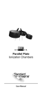
Parallel Plate
Ionization Chambers
User Manual
.
WWW.
.COM
Parallel Plate
Ionization Chambers
STANDARD IMAGING INC.
3120 Deming Way
Middleton, WI 53562-1461
Nov / 2012 ©2012 Standard Imaging Inc.
DOC #80332-09
TEL 800.261.4446
TEL 608.831.0025
FAX 608.831.2202
General Precautions
Warnings and Cautions alert users to dangerous conditions that can occur if instructions in the manual are
not obeyed. Warnings are conditions that can cause
injury to the operator, while Cautions can cause damage to the equipment.
WARNING: Electrical shock hazard when
connected to 300V bias supply.
WARNING: Exradin Ion Chambers are
intended for quality assurance and calibration
measurements. They are not intended to be
connected to a patient for real-time dosimetry
measurements.
CAUTION: Proper use of this device depends
on careful reading of all instructions and labels.
CAUTION: Do not drop, mishandle, or
disassemble unit since it may result in change of
calibration factor, or damage. Refer all servicing
to qualified individuals.
CAUTION: Do not sharply bend triaxial
cable. Damage to the cable may result
in high leakage currents.
CAUTION: The A20 is designed for 70kV
application and below without a build-up cap.
CAUTION: The A20 is not intended for water
tank applications.
CAUTION: The A20 should only be irradiated
head-on, which is perpendicular to the window
and is similar to other parallel plate ion chambers.
It should never be irradiated along its length.
CAUTION: For best performance, and when
practical, use ion chambers as calibrated,
matching the sign of the charge collected and the
collecting electrode bias with that found on the
calibration documents. Measurements performed
outside of the calibrated parameters and/or
manufacturer recommended specifications should
be independently verified, and used with care.
i
Table of Contents
PAGE
i
General Precautions
1
General Operation
3Calibration
4
Parts and Accessories
4
General Chamber Specifications
5
Exradin A10 Ion Chamber
5
Exradin 11 Ion Chamber
6
Exradin 11TW Ion Chamber
6
Exradin A20 Ion Chamber
7
Service Notes
10 Service Policy
11 Customer Responsibility
12Warranty
3120 Deming Way
MIDDLETON, WI 53562-1461 USA
WWW.STANDARDIMAGING.COM
This manual applies to the following parallel plate
chamber models:
Model
REF
A10
A11
P11
T11
A11TW
P11TW
T11TW
A20
92702
92701
92703
92704
92708
92709
92710
92736
General Operation
All Exradin parallel plate chambers are attached to a
1.5 m length of low-noise flexible triaxial cable that is
terminated by a triaxial or coaxial connector. The collector of the chamber is common with the center wire of the
cable and the center contact of the connector. The guard
is common with the inner cable braid and the middle connector contact, in the case of triaxial connectors, and the
connector body, in the case of coaxial connectors. The
window (outer electrode), usually ground, is common with
the outer braid of the cable and the connector body, in the
case of triaxial connectors, and the pigtail extending out
the rear of coaxial connectors.
1
General Operation Continued
The design of Exradin chambers requires that the collector
and guard operate at essentially the same potential. The
polarizing potential, supplied by an electrometer, is applied
between the window and the guard as shown in Figure
1. Either polarity may be applied to the window and either
the window or guard may be grounded. Safety and other
considerations recommend grounding the window, which
then requires an electrometer with a floating input.
All Exradin chambers can support 1000 V between window
and guard. However, depending on the particular circumstance and radiation intensity, as little as 90 V may yield
essentially 100% charge collection.
LOW-NOISE
WINDOW
COLLECTOR
GUARD
ELECTROMETER
Figure 1: Parallel Plate Chamber and Electrometer
Because Exradin ionization chambers do not exhibit voltage soakage phenomena, readings of ionization current
may be made immediately after application of the polarizing potential. However, it is good practice to pause a
minute or two after changing the potential to allow switching transients induced in the electrometer to completely
subside. Such transients are most evident in the rate
(current) mode.
Operating Instructions
1. With nothing connected to the input jack of the electrometer, turn the power on and wait at least 15 minutes
for warm up.
2. Verify the leakage of the electrometer is within the
manufacturer’s stated acceptable limits.
3. Connect the ionization chamber to the electrometer
and apply 300 VDC or the desired voltage bias.
4. Allow the electrometer and ionization chamber system
at least 10 minutes to stabilize, making certain that all
cabling is lying flat and unkinked.
2
General Operation Continued
5. Verify the leakage of the ionization chamber is within
the manufacturer’s stated acceptable limits. If measured in the presence of background sources, note that
this signal will add to the leakage of the chamber.
6. Some electrometers, such as the Standard Imaging
MAX 4000 Electrometer, allow the user to zero the
device at any time. If desired, perform this system
zeroing now.
7. Check the system leakage. Take a reading without
exposing the chamber to radiation. This reading
should be less than 0.1% of the final signal expected.
If it is not, the leakage should be subtracted from the
signal.
8. Measure atmospheric temperature and pressure. For
well chambers, measure the temperature in the well of
the chamber.
9. Insert the ion chamber and take at least 3 measurements. Generally, the measurements should not be
moving in only one direction (i.e. three readings that
continue to drop and hence may not yet be stabilized).
If a current measurement is done, allow sufficient time
for value to stabilize.
10.Analyze the data taking into account the average of
the readings, system leakage, temperature/pressure
corrections, calibration factors and any other appropriate corrections to be made. Keep in mind that the
calibration factor consists of the electrometer calibration and the ionization chamber calibration factor.
11. When all measurements are completed, set bias voltage to 0 VDC, turn off the electrometer and disconnect
the ionization chamber.
Calibration
As is standard practice for other ionization chambers, it
is recommended that Exradin chambers be calibrated
every (2) years. This calibration should be performed by
an Accredited Dosimetry Calibration Laboratory (ADCL).
Standard Imaging offers calibrations from the University
of Wisconsin ADCL. You need only one purchase order
to cover calibrations, shipping and handling, and service.
Standard Imaging hand carries all instruments to and from
the University of Wisconsin ADCL.
3
Parts and Accessories
REF
Description
72136
72137
72130
72131
72132
72133
A10 Waterproof cap; 1.0 mm; acrylic
Model 11 Waterproof cap; 1.0 mm; acrylic
A11 Co-60 Calibration Cap; 1.8 mm
P11 Co-60 Calibration Cap; 3.2 mm
T11 Co-60 Calibration Cap; 3.4 mm
A11TW Co-60 Calibration/
Waterproof Cap; 2.8 mm
P11TW Co-60 Calibration/
Waterproof Cap; 4.2 mm
T11TW Co-60 Calibration/
Waterproof Cap; 4.4 mm
A20 – 70 - 100 keV Buildup Cap,
15.4mg/cm2; Polyimide
A20 – 300 keV and above buildup cap,
88 mg/cm2, C552
72134
72135
72271
72272
General Chamber Specifications
Nominal Collection
Efficiency:
Maximum Polarizing
Potential:
Nominal Inherent Leakage
Currents:
Low-Noise Triaxial Cable:
100%
1000 V
Humidity:
Temperature:
Pressure:
10-15 A
50 ohms, 29 pF/ft, 1.5 m long
(2.5 m long for the A20)
Triaxial BNC Plug (2-Lug Male);
unless requested as other
Integral with triaxial connector
(shell of chamber is common with
connector body)
10-80%, non-condensing
-15 - 50 OC
680 - 770 mm Hg
Product Standards:
IEC 60601-11, IEC 607311
Signal Connector:
High Voltage Connector:
1
Designed to Meet
4
Exradin A10 Ion Chamber
A10 (REF 92702)
Collecting Volume:
Nominal Calibration Factor:
Centroid of Collecting Volume:
Collector Diameter:
Window-Collector Gap:
Window:
0.051 cm3
60 R/nC
1.0 mm from top of window
5.4 mm
2.0 mm
Polyimide film, 3.86 mg/cm2
Window Support Rings, Collec- A10 - Shonka Air-Equiv.
tor, and Guard Material:
plastic C552
Included Waterproofing Cap:
Polarity:
Wall thickness of 1.0 mm;
constructed of acrylic; TG-51
compliant
< 1%
Exradin 11 Ion Chamber
A11 (REF 92701)
P11 (REF 92703)
T11 (REF 92704)
Collecting Volume:
Nominal Calibration Factor:
Centroid of Collecting Volume:
Collector Diameter:
Window-Collector Gap:
Window:
0.62 cm3
5.5 R/nC
2.0 mm from top of window
20.0 mm
2.0 mm
1.0 mm
Window Support Rings, Collec- A11 - Shonka Air-Equiv.
tor, and Guard Material:
plastic C552
P11 - Polystyrene-Equiv.
plastic D400
T11 - Shonka Tissue-Equiv.
plastic A150
5
Exradin 11TW Ion Chamber
A11TW (REF 92708)
P11TW (REF 92709)
T11TW (REF 92710)
Collecting Volume:
Nominal Calibration Factor:
Centroid of Collecting Volume:
Collector Diameter:
Window-Collector Gap:
Window:
0.92 cm3
3.4 R/nC
1.5 mm from top of window
20.0 mm
3.0 mm
Polyimide film, 3.86 mg/cm2
Window Support Rings,
Collector, and Guard Material:
A11TW - Shonka Air-Equiv.
plastic C552
P11TW - Polystyrene-Equiv.
plastic D400
T11TW - Shonka TissueEquiv. plastic A150
Included Waterproofing Cap:
Wall thickness of 1.0 mm;
constructed of acrylic; TG-51
compliant
Exradin A20 Ion Chamber
A20 (REF 92736)
Collecting Volume:
Nominal Calibration Factor:
Centroid of Collecting Volume:
Collector Diameter:
Window-Collector Gap:
Window:
Window Support Rings,
Collector, and Guard Material:
6
0.074 cm3
3.7 x 10⁸ Gy/C or 4.2 x 10¹⁰ R/C
1.80 mm from top of window
1.93 mm
5.0 mm
Kapton film, 7.72 mg/cm2
Shonka Air-Equiv. plastic C552
Service Notes
Stem
The one-piece polycarbonate stem (0.9 cm OD, 7.6 cm
long) found on these chambers is an integral part of the
chamber assembly and is not to be removed under any
circumstances.
Venting
These particular ionization chambers are equipped with a
Tygon® tube secured to the chamber stem and running the
full length of the triaxial cable. (The triaxial cable is inside
the tubing.) The tubing is sealed to the chamber stem,
and is open to ambient conditions at the connector end.
This tubing is not intended to be removed or altered by the
customer, and doing so will void the warranty.
Calibration Cap
Calibration caps constructed of the same material as the
major elements of the chamber are available to provide
more than adequate build-up for Cobalt-60 radiation.
To secure cap on chamber: Simply place cap over chamber window until it bottoms.
Waterproofing Cap (A10 and 11TW ONLY)
The waterproofing cap, available for these chambers, is
made of acrylic and has a 1.0 mm thick window as recommended by the AAPM TG-51 protocol. The O-Ring inside
the cap is designed to offer a snug fit to the chamber’s
outer diameter, to ensure its seal.
To secure cap on chamber: press cap firmly down onto
chamber until it bottoms on chamber window ring. Occasionally, the O-Ring inside the cap will become twisted
and prevent complete bottoming. If this occurs, simply
rotate the cap (either clockwise or counterclockwise) while
continuing downward pressure, until it bottoms on chamber
window ring.
To remove cap from chamber: Gently rotate (either clockwise or counterclockwise) cap while pulling slightly upward.
Tygon is a trademark of Saint-Gobain Performance Plastics
7
Service Notes Continued
Kapton® Window (A10, 11TW, and A20 only)
The window is made of thin conducting Kapton film and
is under tension. Touching anything to the window is to
be avoided.
Even though these T versions of Exradin Ion Chambers
are designed to be waterproof, as a result of the hygroscopic properties of A150, they are not recommended for
submerged use in water. Submerged use typically involves
ion chamber use with a water tank.
By definition, the hygroscopic properties of A150 may
cause the material to absorb minute amounts of water
under certain conditions. This water can alter the physical
characteristics of the material to an extent which may cause
the ion chamber’s measurements and calibration factors
to change over time.
Service and Maintenance
There are no user-serviceable parts within these
ionization chambers. Under no circumstance should
the user attempt to repair or disassemble the chamber
and/or connector, as the warranty will become void
and the calibration factor will change. Under normal
use, the chambers should provide years of troublefree service.
If assistance is desired in the proper disposal or
recycling of this product (including accessories
and components), after its useful life, please return
to Standard Imaging.
8
Service Notes Continued
Cleaning Triax Connectors on Ion Chambers and
Extension Cables
Over the years, Standard Imaging has had product
reports of drift or leakage involving its ion chambers. During the investigation and/or servicing of these products
it became apparent a significant portion of these reports
were caused by dirty triax connectors. The cause is typically dust that has collected on the inside connector.
To minimize these reports and unnecessary service,
Standard Imaging is providing a triax connector cleaning procedure. This triax connector cleaning procedure should be periodically completed or whenever
there are concerns of drift or leakage. Heavier product
use may require more frequent cleanings.
Prior to cleaning a triax connector, ensure:
• The ion chamber is disconnected from the electrometer.
• There is no water or moisture visible in the triax
connector.
To clean a dirty triax connector:
• Remove the connector cap (if applicable).
• Use only a dry and oil free compressed air source,
such as Chemtronics® Ultra Jet.
• Gently blow dirt and contaminants from the inside
of the connector, moving the air source in a circular
manner a few inches from the connector.
After cleaning a dirty triax connector:
• Use the connector cap when not in use (if applicable).
Do not:
• Use sharp objects to attempt to clean a dirty triax
connector.
• Use a compressed gas other than air.
• Use a compressed gas source that may have
moisture or oil in the source or lines.
• Use your mouth to blow on the connector.
• Disassemble the connector.
• Touch the internal parts of the connector with your
finger.
If this procedure does not resolve the drift or leakage
issues, contact the Customer Service Administrator to
coordinate the return the product to Standard Imaging
for further service.
If there are any questions or comments regarding this
information, please contact Standard Imaging or your
authorized dealer.
9
Service Policy
If service, including recalibration, is required, please contact
Standard Imaging’s Customer Service department by phone or
email prior to shipping the product. Standard Imaging’s Customer
Service and Technical Service staff will attempt to address the
product issue via phone or email. If unable to address the issue,
a return material authorization (RMA) number will be issued.
With the RMA number, the product can be returned to Standard
Imaging. It is the responsibility of the customer to properly
package, insure and ship the product, with the RMA number
clearly identified on the outside of the package. The customer
must immediately file a claim with their carrier for any shipping
damage or lost shipments. Return shipping and insurance is
to be pre-paid or billed to the customer, and the customer may
request a specific shipper. Items found to be out of warranty
are subject to a minimum service fee of 1 hour labor (excluding
recalibrations) for diagnostic efforts and require a purchase
order (PO) before service is performed. With concurrence from
customer, the product may be replaced if it is unserviceable or if
the required service is cost prohibitive. Products incurring service
charges may be held for payment. Standard Imaging does not
provide loaner products. See the Standard Imaging Warranty
and Customer Responsibility for additional information.
Return Policy
No merchandise will be accepted for credit without prior approval
of return. Please contact Standard Imaging’s Customer Service
Department to receive a return authorization number before
returning any merchandise for exchange or credit. Products
manufactured by Standard Imaging must be returned within thirty
days of receipt of order in ‘like new’ condition. No credit will be
given for products returned after thirty days from receipt of order.
A minimum twenty percent restocking fee will be charged on all
returned merchandise. All materials returned must be shipped
pre-paid. Credit for returned goods will be issued to customer's
account for use against future purchases of merchandise only.
Special orders, custom products, re-sale (not manufactured by
Standard Imaging) products, and ADCL calibrations will not be
accepted for return credit or exchange.
Serialization Information
Standard Imaging products that are serialized contain coded logic in the serial number
which indicates the product, day and year of
manufacture, and a sequential unit number
for identification:
A YY DDD X
A
YY
Unique product ID
Last two digits of the year
(e.g. 1999 = 99, 2000 = 00)
DDD Day of the year (1< DDD < 365)
X
Unique unit ID Number (1 < X < 9)
10
Customer Responsibility
This product and its components will perform properly and
reliably only when operated and maintained in accordance with
the instructions contained in this manual and accompanying
labels. A defective device should not be used. Parts which
may be broken or missing or are clearly worn, distorted or
contaminated should be replaced immediately with genuine
replacement parts manufactured by or made available from
Standard Imaging Inc.
CAUTION: Federal law in the U.S.A. and Canadian
law restrict the sale, distribution, or use of this
product to, by, or on the order of a licensed medical
practitioner. The use of this product should be
restricted to the supervision of a qualified medical
physicist. Measurement of high activity radioactive
sources is potentially hazardous and should be
performed by qualified personnel.
CAUTION: As desired by IAEA, English is the
default language for labeling and manuals. If
translated versions are available, resolve any
differences in favor of the English versions.
WARNING: Proper use of this device depends on
careful reading of all instructions and labels.
WARNING: Where applicable, Standard Imaging
products are designed to be used with the
versions of common radiation delivery devices,
treatment planning systems and other products
or systems used in the delivery of ionizing
radiation, available at the time the Standard
Imaging product is released. Standard Imaging
does not assume responsibility, liability and/or
warrant against, problems with the use, reliability,
safety or effectiveness that arise due to the
evolution, updates or changes to these products
or systems in the future. It is the responsibility of
the customer or user to determine if the Standard
Imaging product can be properly used with these
products or systems.
Should repair or replacement of this product become
necessary after the warranty period, the customer should
seek advice from Standard Imaging Inc. prior to such repair or
replacement. If this product is in need of repair, it should not
be used until all repairs have been made and the product is
functioning properly and ready for use. After repair, the product
may need to be calibrated. The owner of this product has
sole responsibility for any malfunction resulting from abuse,
improper use or maintenance, or repair by anyone other than
Standard Imaging Inc.
The information in this manual is subject to change without
notice. No part of this manual may be copied or reproduced
in any form or by any means without prior written consent of
Standard Imaging Inc.
11
Warranty
Standard Imaging, Inc. sells this product under the warranty herein set forth.
The warranty is extended only to the buyer purchasing the product directly from
Standard Imaging, Inc. or as a new product from an authorized dealer or distributor
of Standard Imaging, Inc.
For a period provided in the table below from the date of original delivery to the
purchaser or a distributor, this Standard Imaging, Inc. product, provided in the table
is warranted against functional defects in design, materials and workmanship,
provided it is properly operated under conditions of normal use, and that repairs
and replacements are made in accordance herewith. The foregoing warranty shall
not apply to normal wear and tear, or if the product has been altered, disassembled
or repaired other than by Standard Imaging, Inc. or if the product has been subject
to abuse, misuse, negligence or accident.
Product
Warranty Period
Standard Imaging
Ionization Chambers
2 years
Standard Imaging
Well Chambers
2 years
Standard Imaging Electrometers
5 years
Standard Imaging
BeamChecker Products
2 years
Standard Imaging
Software Products
1 year
All Other Standard
Imaging Products
1 year
Standard Imaging
Custom Products
1 year
Standard Imaging
Remanufactured Products
180 days
Standard Imaging
Custom Select Products
90 days
Consumables
90 days
Serviced Product
90 days
Resale Products
As defined by the Original Equipment Manufacturer
ADCL Product Calibration
(Standard Imaging uses the
UW-ADCL for recalibrations
required under warranty, unless
otherwise requested)
0 - 90 days = 100% of ADCL Calibration Costs
91 - 182 days = 75% of ADCL Calibration Costs
183 – 365 days = 50% of ADCL Calibration Costs
366 – 639 days = 25% of ADCL Calibration Costs
(days from date of shipment to customer)
Standard Imaging’s sole and exclusive obligation and the purchaser’s sole and
exclusive remedy under the above warranties are, at Standard Imaging’s option,
limited to repairing, replacing free of charge or revising labeling and manual content
on, a product: (1) which contains a defect covered by the above warranties; (2)
which are reported to Standard Imaging, Inc. not later than seven (7) days after
the expiration date of the warranty period in the table; (3) which are returned to
Standard Imaging, Inc. promptly after discovery of the defect; and (4) which are
found to be defective upon examination by Standard Imaging Inc. Transportation
related charges, (including, but not limited to shipping, customs, tariffs, taxes, and
brokerage fees) to Standard Imaging are the buyer’s responsibility. This warranty
extends to every part of the product excluding consumables (fuses, batteries,
or glass breakage) or material reactions. Standard Imaging, Inc. shall not be
otherwise liable for any damages, including but not limited to, incidental damages,
consequential damages, or special damages. Repaired or replaced products are
warranted for the balance of the original warranty period, or at least 90 days.
This warranty is in lieu of all other warranties, express or implied, whether statutory
or otherwise, including any implied warranty of fitness for a particular purpose. In
no event shall Standard Imaging, Inc. be liable for any incidental or consequential
damages resulting from the use, misuse or abuse of the product or caused by any
defect, failure, malfunction or material reactions of the product, whether a claim
of such damages is based upon the warranty, contract, negligence, or otherwise.
This warranty represents the current standard warranty of Standard Imaging,
Inc. Please refer to the labeling or instruction manual of your Standard Imaging,
Inc. product or the Standard Imaging, Inc. web page for any warranty conditions
unique to the product.
12