1
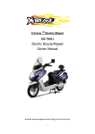
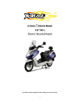
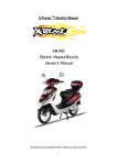
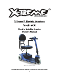
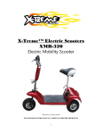
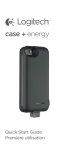
XB-200LI / XB-210LI Super Folding Electric Mini Bicycle User Manual (PHOTO MAY VARY) PLEASE BE SAFE WHEN RIDING ALWAYS WEAR A HELMET AND OBEY ALL LAWS! 1 IMPORTANT INFORMATION FULLY CHARGE BATTERIES BEFORE FIRST USE - Batteries should be fully charged immediately when they are received and immediately after each use for the recommended charge times (see below) • L i F e P o 4 Lithium Batteries: 4-6 hours FACTORS TO MAXIMIZE THE RANGE OF YOUR ELECTRIC BICYCLE RIDER INPUT - the more the rider pedals the further the distance traveled. Continuous riding, as opposed to frequent stopping and starting, will yield the greatest range possible ELEVATION GAIN - the flatter the road the further the distance traveled WEATHER - cold weather can adversely affect the battery capacity TERRAIN - the smoother the terrain (roadways vs. fire roads, etc.) the further the distance traveled RIDER WEIGHT - the lighter the rider, resulting in less drain on the batteries, the further distance traveled RIDER BICYCLE MAINTENANCE - a properly maintained bicycle will yield the greatest range possible RIDER TIRE PRESSURE - properly inflated tires have less rolling resistance and will be easier to pedal BATTERIES - properly charged and maintained batteries will yield the greatest range possible. Batteries stored in cold areas (below 50 degrees Fahrenheit / 10 degrees Celsius) will show reduced range. Batteries that have not been kept in optimum condition will show reduced range and run time. 2 TABLE OF CONTENTS Important Information…………………………………………………………………………………………………….. 2 Table of Contents……………………………………………………………………………………………………………. 3 Getting To Know Your XB-200Li………………………………………………………………………………………. 4 Getting To Know Your XB-210Li………………………………………………………………………………………. 5 Before You Ride………………………………………………………………………………………………………………. 6-7 About This Manual……………………………………………………………………………………………… 7 General Warning………………………………………………………………………………………………….7 A Special Note for Parents………………………………………………………………………………….. 7 Operating Process…………………………………………………………………………………………………………… 8-10 Folding………………………………………………………………………………………………………………… 8 Unfolding……………………………………………………………………………………………………………. 8-9 Seat Height…………………………………………………………………………………………………………. 9 Handlebar Adjustment & Height………………………………………………………………………… 9 Battery Charging…………………………………………………………………………………………………. 10 Bicycle Assembly……………………………………………………………………………………………………………… 10-14 Getting Started…………………………………………………………………………………………………….10 Stem and Handlebars…………………………………………………………………………………………. 11 Forks…………………………………………………………………………………………………………………… 11-12 Seat and Seat Post……………………………………………………………………………………………… 12-13 Front Wheel……………………………………………………………………………………………………….. 13 Disc Brakes…………………………………………………………………………………………………………. 14 Drivetrain…………………………………………………………………………………………………………… 14 Battery Care and Information…………………………………………………………………………………………. 15-17 Battery Care……………………………………………………………………………………………………….. 15 Storage……………………………………………………………………………………………………………….. 15-16 FAQ…………………………………………………………………………………………………………………….. 16 Charger………………………………………………………………………………………………………………. 16-17 Bicycle Care…………………………………………………………………………………………………………………….. 18 Basic Maintenance…………………………………………………………………………………………….. 18 Safety Checklist………………………………………………………………………………………………………………. 19-20 Specifications………………………………………………………………………………………………………………….. 21 3 GETTING TO KNOW YOUR XB-200LI 1 4 2 6 5 3 7 8 9 10 16 11 13 12 1. 2. 3. 4. 5. 6. 7. 8. LED Headlight Hand Brake Hand Throttle Left Grip with PAS (Pedal Assist System) Folding Handlebar & Stem Seat Seat Post Folding Lift Handle 14 9. 10. 11. 12. 13. 14. 15. 16. Li-Ion Battery Mud Flap 300W Hub Motor and 12” Rear Wheel Rim Chain Guard Right Crank Arm with Chain Sprocket Pedal 12” Front Wheel Rim Front Fork 4 15 GETTING TO KNOW YOUR XB-210LI 7 1 6 3 2 5 4 1. 2. 3. 4. 5. 6. 7. 16” Front Wheel Rim Front Brake Rotor WinZip Front Caliper Brake Kickstand WinZip Rear Caliper Brake 16” Rear Wheel Rim 300W Hub Motor **Note – all component identified in both images same on for both models except for Front Wheel Rim, Rear Wheel Rim and Hub Motor. 5 BEFORE YOU RIDE! Please read the manual carefully before riding your X-Treme™ XB-200Li bicycle. 1. Your XB-200Li has been equipped with a brake switch-off device. Left and right brake levers are installed with a brake power switch. No matter which brake you use while riding the power will be cut off automatically for safety purposes. 2. When the battery output voltage is reached the bottom index, the XB-200Li’s electronic control system will cut off power automatically to protect the battery cycle lifetime. When the battery reaches its bottom voltage you can still ride your e-bike by pedal power. Recharge the battery to full charge for the next cycling time. 3. Please switch off the power of your XB-200Li when it’s not in use. 4. Please ensure your e-bike’s kickstand is locked while parked. 5. Please do not turn on the right switch throttle grip to full throttle during riding. It can cause a large start e-current which may damage your battery. If your e-bike is often ridden this way it may cut the battery cycle lifetimes. 6. Once your XB-200Li is fully charged, riding range can be affected by the road conditions and terrain, rider weight, wind direction and etc. We suggest you to pedal more during the start of the ride and while climbing hills and against the wind to help increase your range and distance and for longer life of the battery and motor. 7. Always try pedaling while riding on muddy or rough road. 8. During your start on the incline when climbing, please first ride by pedal and then start the power switch for the e-motor assist. 9. While cleaning your XB-200Li, wipe with a moist cloth or wet cloth. Never use a water hose or squirt gun for cleaning and washing. 10. DO NOT put oil on the front brake shoes. 11. Occasionally clean the seat post to avoid rusting. You may apply a small amount of oil for lubrication if necessary. 6 ABOUT THIS MANUAL 2- It is important for you to understand your new bicycle. By reading this manual before you go out on your first ride, you’ll know how to get better performance, comfort, and enjoyment from your new bicycle. It is also important that your first ride on your new bicycle is taken in a controlled environment, away from cars, obstacles, and other distractions. GENERAL WARNING Bicycling can be a hazardous activity even under the best of circumstances. Proper maintenance of your bicycle is your responsibility as it helps reduce the risk of injury. This manual contains many “Warnings” and “Cautions” concerning the consequences of failure to maintain or inspect your bicycle. Many of the warnings and cautions say “you may lose control and fall.” Because any fall can result in serious injury or even death, we do not repeat the warning of possible injury or death where ever the risk of falling is mentioned. A SPECIAL NOTE FOR PARENTS It is a tragic fact that most bicycle accidents involve children. As a parent or guardian, you bear the responsibility for the activities and safety of your minor child. Among these responsibilities are to make sure that the bicycle which your child is riding is properly fitted to the child; that it is in good repair and safe operating condition; that you and your child have learned, understand and obey not only the applicable local motor vehicle, bicycle, and traffic laws, but also the common sense rules of safe and responsible bicycling. As a parent, you should read this manual before letting your child ride the bicycle. Please make sure that your child always wears an ANSI, ASTM, SNELL approved bicycle helmet when riding. 7 OPERATING PROCESS FOLDING 1.) Lift the handlebar lock pin on the left side of the handlebar as shown in Figure 1. After you lift the pin you can drop the left handlebar down and rest to the side. Fig 1 2.) Repeat step 1 for the right side as shown in Figure 2. Both handlebar sides will be folded down as shown in Figure 3. 3.) Hold together the Lower Seat Post (A) and Small Support Post (C) as shown in Figure 4. When you clamp these together, the as shown in Figure 5, the Upper Seat Post (Figure 4 – B) will slide into the Lower Seat Post and both will slide down into the position shown in Figure 7. Fig 2 Fig 3 4.) Lift up on the Folding Lift Handle (Figure 4 – D) and this will allow you to fold together the bike as shown in Figure 7. Fig 4 B A D Fig 5 C 5.) Fold the Pedals down as shown in Figure 6. Once all steps are complete your bike should look like folded unit in Figure 7. UNFOLDING Fig 7 1.) Lift up on the Seat and Upper Seat Post until you hear the Lower Seat Post and Small Support lock into place. 2.) Kick the Kickstand back softly. This will allow the frame of the bicycle to open quickly and lock into the open position. Fig 6 3.) Lift up on the handlebars and lock into 8 position. Make any adjustments to the seat height as needed. ***Make sure to check that everything is locked into position prior to riding. SEAT HEIGHT In order to obtain the most comfortable riding position and offer the best possible pedaling efficiency, the seat height should be set correctly in relation to the rider’s leg length. The correct seat height should not allow leg strain from over-extension, and the hips should not rock from side to side when pedaling. While sitting on the bicycle with one pedal at its lowest point, place the ball of your foot on that pedal. The correct seat height will allow the knee to be slightly bent in this position. If the rider then places the heel of that foot on the pedal, the leg should be almost straight. Under no circumstances should the seat post project from the frame beyond its “Minimum insertion” or “Maximum extension” mark. if your seat post projects from the frame beyond these markings, the seat post or frame may break. Prior to your first ride, be sure to tighten the seat clamp properly. a loose seat clamp or seat post binder can cause damage to the bicycle or can cause you to lose control and become injured. Periodically check to make sure that the seat clamp is properly tightened. ! HANDLEBAR ADJUSTMENT & HEIGHT The stem’s “Minimum insertion” mark must not be visible above the top of the handlebar clamp. If the stem is extended beyond this mark, the stem may break or damage the fork’s steering tube, which could cause you to lose control and become injured. Failure to properly tighten the stem binder bolt, the handlebar binder bolt, or the bar end extension clamping bolts may compromise steering action, which could cause you to lose control and become injured. Place the front wheel of the bicycle between your legs and attempt to twist the handlebar/stem assembly using a reasonable amount of force. There should be no play or ability to move the handlebars in relation to the wheel. If you can twist the handlebars while the wheel remains in place, do not ride until proper alignment and is obtained, then tighten all bolts accordingly before use. Handlebar height Maximum comfort is usually obtained when the handlebar height is equal to or slightly higher than the height of the seat. You may wish to try different heights to find the most comfortable position. 9 BATTERY CHARGING Charger Indicator – Red = Charging / Green = Full Battery 1. Plug the connector between the charger and the battery. Next plug the charger to the power source. The LED charger will turn red, which means the charger is on and working. 2. When the LED light turns green, it means the battery is fully charged. Unplug the charger from the power source and then disconnect the charger from the battery. During charging, the battery should be placed in a cool and stable place. Do not place any cover on the battery or charger while using. Ensure no liquids or metal filings diffuse into the charger. If the battery box surface is found to be too hot (higher than 140°F) during charging it may cause malfunction. The power should be cut off at once and the battery should be repaired in an appointed service station. BICYCLE ASSEMBLY GETTING STARTED Open the carton from the top and remove the bicycle. Remove all straps and protective wrapping from the bicycle. Inspect the bicycle and all accessories and parts for possible shortages. It is recommended that the threads and all moving parts in the parts package be lubricated prior to installation. Do not discard packing materials until assembly is complete to insure that no require parts are accidentally discarded. **Note: Your bicycle may be equipped with different style components than illustrated within this manual. ! We recommend that you contact X-Treme if you have doubts or concerns as to your experience or ability to properly assemble, repair or maintain your bicycle. 10 STEM AND HANDLEBARS 1. Remove the protective shipping cap from the stem wedge. 2. Remove the stem plug from the stem. Loosen the stem bolt with a 6mm Allen wrench or 13mm box wrench. 3. Insert the stem into the head tube of the bicycle. Ensure that the minimum 4. Align the stem and handlebar so it is in line with the front wheel. 5. Tighten the stem bolt with a 6mm Allen wrench. Reinsert the stem plug into the Figure 8 plug. 6. Check the headset for smooth rotation and that the top nut is secured tightly. 7. Loosen the 6mm binder bolt and rotate the handlebar so the levers are at a 45 degree angle below the handlebar. 8. Retighten the binder bolt to ensure the handlebar does not rotate in the stem. FORKS Figure 9 There are two different types of forks that vary in styles and dimensions. One type is a rigid fork (Figure 9) consisting of stationary tubing with curved blades. The other type is a suspension fork (Figure 10) consisting of inner stanchion tubes riding on elastomers or springs inside of a straight outer fork leg. This mechanism acts as a shock absorber with a specified amount of travel that varies between models. Some suspension forks are not adjustable and are very difficult to disassemble. If service is needed on a suspension fork, consul t a professional bicycle repair technician. Figure 10 Your bicycle is equipped with a Suspension Fork as shown in Figure 10. 11 Do not attempt to disassemble a suspension fork yourself. Contact X-Treme Scooters for assistance or see a professional bicycle repair technician. If your bike is equipped with a suspension fork, check that the fork compresses and rebounds smoothly. To do this, place the fork dropouts against the ground, push and release the handlebar. The fork will generally compress 1-2” and rebound quickly. Most elastomer type forks will gradually soften with use. SEAT AND SEAT POST Fig 11 Fig 12 B A Your bicycle will come equipped with either a standard or a micro-adjustable seat post. STANDARD SEAT POST Attach the seat to the seat post by first loosening the nuts on the seat clamp. Insert the tapered end of the seat post into the seat clamp until it is at the top of the clamp. Partially tighten the nuts on the seat clamp, then insert the seat assembly into the frame of the bicycle and adjust the seat to the proper height. The seat post must be inserted to at least the “Minimum Insertion” line. Move the quick release lever (shown in Figure 11 - A) to the closed position. You should feel considerable resistance while moving the lever. If not, re-open and tighten the lever and then move it to the closed position. See the section in this manual regarding quick releases for more detailed instructions. Adjust the seat to be centered in the clamp and generally level with the ground and then re-tighten the clamp nuts (show in Figure 12) evenly before riding. Avoiding riding with a loose seat. MICRO-ADJUSTABLE SEAT POST Loosen the seat fixing bolt (shown in Figure 11 – B) and then slide the seat into the clamp. The two seat rails should be fit into the corresponding channels in the clamp. There is usually no need to completely remove the fixing bolt, but it may be necessary in some cases. Partially tighten the seat fixing bolt, then insert the seat assembly into the frame of the bike and adjust 12 the seat to the proper height. The seat post must be inserted to at least the “Minimum Insertion” line. Move the quick release lever to the closed position. You should feel considerable resistance while moving the lever. If not, re-open and tighten the lever, then move it to the closed position. See the section in this manual regarding quick releases for more detailed instructions. Adjust the seat to be centered in the clamp and generally level with the ground, then re-tighten the seat fixing bolt before riding. Avoid riding the bike with a loose seat. **NOTE: Some models may be equipped with a suspension seat post. Some suspension seat posts can be adjusted for stiffness using the preload adjustment screw. To make the suspension stiffer, turn the 6mm Allen screw clockwise. To make the suspension softer, turn the 6mm Allen screw counter-clockwise. The seat post must be inserted so that the minimum insertion mark cannot be seen. The quick release mechanism must be tightened securely to prevent a sudden shift of the seat when riding. Failure to do this may cause loss of bicycle control. FRONT WHEEL Fig 13 XB-210Li Photos vary from actual bike 1. Make sure the brakes are loose enough to allow the brake pads to move easily. 2. Place the front wheel into the fork drop outs as shown in Figure 13. 3. Insert the quick release axle with nut (shown in Figure 14). 4. When the axle is in place, push lever down on the axle to lock into place (shown in Figure 15.) 5. Spin the wheel to make sure it is centered and clears the brake shoes. Tighten brakes if necessary. XB-200Li This unit does not have quick release axle. Front wheel can be installed by axle and nut. Fig 14 **IMPORTANT: It is important to check the front wheel connection to the bicycle. Failure to properly tighten may cause the front wheel to dislodge. Fig 15 13 DISC BRAKES Fig 16 1. Check the tightness of the six disc mounting bolts (Figure 16) that are holding the brake rotor to the wheel. If you need to remove these bolts, be sure to use a thread-locking compound when reinstalling them. 2. Make sure the two bolts securing the caliper adaptor bracket to the fork are tight (Figure 17 – A). 3. Thread the brake cable through the caliper as shown and secure it with the cable fixing bolt (Figure 17 – B). 4. Loosen the two caliper mounting bolts enough to allow the brake caliper to float freely (Figure 18). Fig 17 B A Fig 18 Drivetrain The drivetrain of a bicycle refers to all parts that transmit power to the rear wheel including pedals, chain, chain wheel, crank set and freewheel. Pedals Pedals should be inspected every month, taking note of the following areas: Check correct tightness into the crank arms. If pedals are allowed to become loose, they will not only be dangerous but will cause irreparable damage to the cranks. Left – turn counter clockwise Right - turn clockwise to tighten Check that pedal bearings are properly adjusted. Move the pedals up and down, and right to left, and also rotate by hand. If you detect any looseness or roughness in the pedal bearings then adjustment, lubrication or replacement is needed. Ensure that the front and rear pedal reflectors are clean and securely fitted. 14 BATTERY CARE AND INFORMATION Proper maintenance of batteries will maximize their lifespan and capacity. X-Treme Scooters warranties your new batteries from the date of purchase for 1 full year when properly cared for. Visit www.x-tremescooters.com/support/ for more information. BATTERY CARE Even with proper care, rechargeable batteries do not last forever. Every time the battery is discharged and subsequently recharged, its relative capacity decreases by a small percentage. With proper care, the life span of your batteries is between 500-700 cycles. You can maximize the life of your battery by following the instructions in this guide. Batteries should be fully charged immediately when they are received for the full recommended charge times. LI-Po4 Recommended Charge Time: 4-6 hours. For a complete, 100% charge, leave the battery on the charger for one full hour after the charger indicator light turns green. Never charge batteries for longer than 24 hours. Li-Po4 batteries do not have a “memory.” Partial discharge/charge cycles will not harm the batteries’ capacity or performance. The rated output capacity of a battery is measured at 77°F (25°C). Any variation in this temperature will alter the performance of the battery, and shorten its expected life. High temperatures especially reduce overall battery life & run time. Always be sure to turn the bike/scooter power switch to “OFF” after each use. If you leave the power switch in the “ON” position, or your product has not been charged for a long period of time, the batteries may reach a stage at which they will no longer hold a charge. Be friendly to the environment! Be sure to recycle your old batteries at a local batteryrecycling center. Do not throw them in the garbage! STORAGE When storing your batteries for a long period of time (longer than two months): Charge your batteries every 90 days to avoid capacity loss. Batteries slowly selfdischarge when left unused for a long period of time; if the battery cells are allowed to reach a critically low voltage, their lifespan and capacity will be permanently reduced. Always disconnect your charger from the wall outlet and battery before storing the battery. 15 Avoid storing your batteries in extreme temperatures, whether hot or cold. Batteries are best kept in a cool, dry place. Do not allow batteries to accumulate condensation, as this could cause shorting or corrosion. The recommended storage temperature is between 32 - 77° F (0 - 25°C) Avoid exposing the battery to extreme heat (104°F or higher) for long periods of time. FAQ Q: Do I need to “break-in” my batteries? A: Yes, it is recommended that you perform a “break-in” cycle consisting of three discharge/charge cycles to allow your batteries to reach optimum performance. This involves three complete discharges and three complete recharges. After this initial “break-in” cycle the batteries will have maximum possible performance less line voltage fluctuations under load. Q: Is it normal that the batteries get warm when recharging? A: Yes, it is normal that the batteries will become warm to the touch during the recharging process. This is because the increase of internal resistance and less energy conversion efficiency from electric energy to chemical energy. Q: How long will my batteries last before needing replacement? A: Average battery life depends on use and conditions. Even with proper care, rechargeable batteries do not last forever. Li-Po4 batteries will last between 500-700 cycles. A partial charge/discharge counts fractionally against those numbers; running the battery down halfway then recharging it completely uses up one half of a charge cycle. “End of useful life” refers to the point at which a battery can no longer supply 80% of its original rated capacity in ampere- hours. After this point, the aging process will accelerate and the battery will need to be replaced. CHARGER The electric bicycle comes with its own “Smart Charger” that connects with an easy-access charger port for recharging the batteries. This charger unit has LED lights that show the battery charge status. Refer to the instructions that appear on the charger unit and its instructions. Batteries work best when they have a full charge, so always be sure to recharge them fully after each ride. If you leave them in a run-down condition without recharging them it will shorten their life expectancy. 16 Li-Po4 Lithium Batteries – charge for 4-6 hours for full charge. The charger may get warm to the touch, so make sure you charge your battery in an open area and do not lie anything on the charger unit while charging. Although you cannot over-charge the batteries, we recommend that you do not leave the charger plugged in for more than 24 hours. If your charger shows a solid green light after charging for a short time, your battery may have only been partially discharged (short ride) or this may be the sign of a partially worn out battery with reduced storage capacity. Continue charging for the full time, to cover all bases. If the battery still has not charged you may need to replace it. Even with proper care, a rechargeable battery does not last forever. Average battery life depends on use and conditions. ! The charger and charger port should be regularly inspected for damage (cord, plug, enclosure, etc.). If damage is found stop using the affected part until it can be repaired or replaced. 17 BICYCLE CARE BASIC MAINTENANCE The following procedures will help you maintain your electric bicycle for years of enjoyable riding. 1. After initial set up, be sure to check wheel spokes to make sure they are properly fitted. Be sure to check again after a few rides to ensure proper break in. (This does not apply to the XB-200.) Follow up with monthly checks. 2. Properly maintain the batteries by keeping them fully charged when not in use. 3. Do not ride your e-bike in the water (damp roads, puddles, rain streams, etc.) and never immerse it in water as the electrical system may be damaged. 4. Periodically check the wiring and connectors to ensure there is no damage and the connectors have good continuity. 5. For painted frames, dust the surface and removed any loose dirt with a dry cloth. To clean, wipe with a damp cloth soaked in a mild detergent mixture. Dry with a cloth and polish with car or furniture wax. Use soap and water to clean plastic parts and rubber tires. Chrome plated bikes should be wiped over with a rust preventative fluid. 6. Store your e-bike under shelter. Avoid leaving it in the rain or exposed to corrosive materials. 7. Riding on the beach or in coastal areas exposes your e-bike to salt which is very corrosive. Wash your bike frequently and wipe or spray all unpainted parts with an anti-rust treatment. Make sure wheel rims are dry so braking performance is not affected. After rain, dry your bicycle and apply anti-rust treatment. 8. If paint has become scratched or chipped to the metal, use touch up paint to prevent rust. Clear nail polish can also be used as a protective measure. 9. Regularly clean and lubricate all moving parts, tighten components and make adjustments as required. 10. The use of alloy components and BED, SATIN and TITANIUM surface treatments minimizes the number of places where rust can surface. 18 SAFETY CHECKLIST Before every ride, it is important to carry out the following safety checks: 1. Brakes • Ensure front and rear brakes work properly. • Ensure brake calipers are not over worn and are correctly adjusted. • Ensure brake control cables are lubricated, correctly adjusted and display no obvious wear. • Ensure brake control levers are lubricated and tightly secured to the handlebar. 2. Wheels and tires • Ensure tires are inflated to within the recommended limit as displayed on the tire sidewall. • Ensure tires have tread and have no bulges or excessive wear. • Ensure rims run true and have no obvious wobbles or kinks. • Ensure all wheel spokes are tight and not broken. • Check that axle nuts are tight. If your bicycle is fitted with quick release axles, make sure locking levers are correctly tensioned and in the closed position. 3. Steering • Ensure handlebar and stem are correctly adjusted and tightened, and allow proper steering. • Ensure that the handlebars are set correctly in relation to the forks and the direction of travel. • Check that the headset locking mechanism is properly adjusted and tightened. • If the bicycle is fitted with handlebar end extensions, ensure they are properly positioned and tightened. 4. Chain • Ensure chain is oiled, clean and runs smoothly. • Extra care is required in wet or dusty conditions 5. Bearings • Ensure all non-sealed bearings are lubricated, run freely and display no excess movement, grinding or rattling. • Check headset, wheel bearings, pedal bearings and bottom bracket bearings. 6. Cranks and Pedals • Ensure pedals are securely tightened to the cranks. • Ensure cranks are securely tightened to the axle and are not bent. 7. Frame and Fork • Check that the frame and fork are not bent or broken. • If either is bent or broken, they should be replaced. 19 8. Accessories • Ensure that all reflectors are properly fitted and not obscured. • Ensure all other fittings on the bike are properly and securely fastened, and functioning. • Ensure the rider is wearing a helmet. 9. Motor and Throttle • Ensure motor is functioning properly. • Ensure throttle is functioning properly. 10. Battery pack • Ensure the batteries are in good operation condition and kept fully charged. 20 SPECIFICATIONS Battery: 24V/8AH LiPo4 Lithium Battery Frame: Alloy 6061-T6, TIG welded Front Fork: Alloy suspension front fork Handlebar: Alloy, with adjustable alloy handlebar stem with scale Cranks and Chain wheel: Forged alloy cranks and single steel chain wheel Brake: F/R WinZip disc brakes, full alloy brake lever Front Hub: XB-210Li - Quick Release Alloy Front Hub XB-200Li – Aluminium 12” Front Wheel Rear Hub: XB-210 Li -300W Quick Release Sealed Wheel Hub Motor XB-200Li – Aluminium 12” Rear Wheel Rim: 16” Alloy, double wall Seat: Low Profile super soft, with double rubber spring Seat Post: Alloy suspension Tire: XB-210Li – 16 x 1.75” XB-200Li – 12” 21 DO NOT RETURN TO STORE IF YOU NEED HELP CALL OR GO ONLINE 1-253-777-0690 www.x-tremescooters.com/support/ For General Information or Parts Visit www.x-tremescooters.com 22 Revised 5/22/13