1
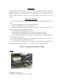
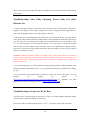
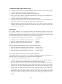
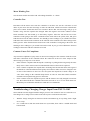
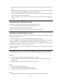
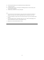
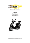
X-Treme TM Electric Moped XB-700Li Electric Bicycle/Moped Owner Manual Read this manual completely before riding your electric bicycle 1 DO NOT RETURN TO STORE! Do not use this vehicle for the first time until you have inflated the tires to the correct PSI and completely charged the battery. Failure to follow these instructions may damage your vehicle and void your warranty. CALL OR GO ONLINE 1-253-777-0690 www.x-tremescooters.com/support/ For General Information or Parts Visit www.x-tremescooters.com Table of Contents Table of Contents……………………………………………………………………………….. 2-3 Riding Safety …………………………………………………………………………………… 4-6 Product Features………………………………………………………………………………… 7 Package Contents………………………………………………….……………………………. 8 Assembly Instructions…………………………………………….…………………………… 8-13 Front Wheel & Brake……………………………………………………………………… 8-9 Handle Bar Installation……………………………………………………………………. 9-10 Windshield Installation……………………………………………………………………. 10-11 Backrest/Pedals/Mirror Installation……………………………………………………….. 12 Battery Connection & Initial Charging Instructions………………………………………. 13 Tire Inflation………………………………………………………………………………. 13 Product Specification…………….……………………………………………………………... 14 Operation………………………………………………………………………………………... 15 Riding Tip Checklist……………………….…………………………………………………… 15 Battery Charging & Safety……………………………………………………………………… 15-16 Basic Maintenance & Schedule………………………………………………………………… 17 Rear Wheel Assembly Instructions……………………………………………………………. 18-19 Front Wheel Removal Instructions……………………………………………………………... 19 2 Front Wheel Installation Instructions………………………………………………………….. 20 Other Helpful Instructions……………………………………………………………………… 20 How To Guide…………………………………………………………………………………... 22-26 How To Adjust Drum Brakes…………………………………………………………….. 22 How To Install Bearings………………………………………………………………….. 22 How To Center Handle Bars……………………………………………………………… 22 How To Align Front Forks………………………………………………………………… 22 How To Replace Controller……………………………………………………………….. 23 How To Replace Rear Inner Tube………………………………………………………….23 How To Remove Hub Motor……………………………………………………………… 23 How To Replace Throttle…………………………………………………………………. 23-24 How To Check Brake Safety Switch……………………………………………………… 24 How To Test Rear Wheel & Controller…………………………………………………… 24 How To Check Voltage……………………………………………………………………. 24-25 How To Test Motor Sensors………………………………………………………………. 25-26 Troubleshooting………………………………………………………………………………… 26-34 Scooter Won’t Run, Charger Light Stays Green………………………………………….. 26 Scooter Won’t Run, Charger Light Stays Red & Green………………………………….. 26 Is It My Throttle Or My Controller?.................................................................................... 26-27 Throttle Voltage Test………………………………………………………………………. 27 Intermitted Power Loss……………………………………………………………………. 27-28 No Power………………………………………………………………………………….. 28-29 After Fully Charging, Powers Only For Short Distance Use…………………………….. 29 Scooter On, Won’t Run…………………………………………………………………… 29 Scooter Won’t Move……………………………………………………………………… 30 Charger……………………………………………………………………………………. 30 Hub Motor Tests………………………………………………………………………….. 31-32 Changing Charging Output From 230V To 110V………………………………………… 32-33 Bad Brake Switch?............................................................................................................ ... 33 Bad Ignition Switch?............................................................................................................ 33 Security System Malfunctioning, Causing Ticking………………………………………. 33-34 Support………………………………………………………………………………………….. 35 3 RIDING SAFETY Like any sport, biking carries the risk of injury and damage. By choosing to ride the XB-700Li, you assume all responsibility for these risks. Thus, you need to know and practice the rules of safe and responsible riding. YOUR INSURANCE POLICIES MAY NOT PROVIDE COVERAGE FOR ACCIDENTS INVOLVING THE USE OF THIS ELECTRIC BICYCLE. TO DETERMINE IF COVERAGE IS PROVIDED YOU SHOULD CONTACT YOUR INSURANCE COMPANY OR AGENT. Safety Basics: Do’s and Don’ts The Do’s o Always conduct a Safety Check before you ride your XB-700Li. Be thoroughly familiar with the controls of your XB-700Li. o Always wear an approved helmet when riding your XB-700Li. manufacturer’s instructions for fit, use and care of your helmet. o Always keep body parts and other objects away from the spinning wheels of your XB-700Li. o Always wear shoes that will stay on your feet and will stay on the floorboard. o Wear bright, visible clothing that is not so loose that it can catch on moving parts of the XB-700Li or objects at the side of the road or trail. o Think about your speed, and keep your speed consistent with safe operating conditions. Follow the helmet The Don’ts o Never ride with headphones. They mask traffic sounds, distract you from concentrating on your surroundings, and their wires can tangle in the moving parts of the XB-700Li, causing you to lose control. o Never ride barefoot or wearing sandals. o Don’t jump with your XB-700Li. It puts great stress on everything from frame and forks to drive train. Riders who insist on jumping their XB-700Li risk serious damage to their XB-700Li as well as to themselves. o Never carry anything which obstructs your vision or your complete control of the XB-700Li or which could become entangled in the moving parts of the XB-700Li. o Never hitch a ride by holding on to another vehicle. o Never ride your XB-700Li while under the influence of alcohol or other drugs. o If possible, avoid riding in bad weather, when visibility is obscured, at dusk or in the dark, or 4 when you are very tired. Each of these conditions increases the risk of accident. o Never allow children to ride. Never allow others to ride without reading and understanding these instructions. Operating Reminders and Suggestions o Review all instructions carefully before riding the XB-700Li. o Follow all rules and regulations in your area for operating a motorized bicycle. Obey the same road laws as all other road vehicles, including yielding the right-of-way to pedestrians, and stopping at red lights and stop signs. o Ride predictably and in a straight line. Never ride against traffic. o Ride defensively. To other road users, you may be hard to see. o Concentrate on the path ahead. Avoid potholes, gravel, dirt, wet road, oil, curbs, speed bumps, drain grates and other obstacles. o Be alert for unexpected events, such as opening car doors or cars backing out of concealed driveways. o Be extra careful at intersections and when preparing to pass other vehicles. o Don't carry packages or passengers that will interfere with your visibility or control of the bike. Don't use items that may restrict your hearing. o Maintain a comfortable stopping distance from all other riders, vehicles and objects. Safe braking distance and forces are subject to the prevailing weather and road conditions. Wet Weather Riding Wet weather impairs traction, braking and visibility, both for the rider and for other vehicles sharing the road. The risk of accident is dramatically increased in wet conditions. In wet weather you need to take extra care. In wet conditions, the stopping power of your brakes (as well as the brakes of other vehicles sharing the road) is dramatically reduced. This makes it harder to control speed and easier to lose control. To make sure that you can slow down and stop safely in wet conditions, apply your brakes earlier and more gradually than you would under normal, dry conditions. Decrease your riding speed, avoid sudden braking, and take corners with additional caution. Keep in mind that there is a direct, but inverse, relationship between speed and controllability. Be more visible on the road. Wear reflective clothing and use safety lights. Potholes and slippery surfaces such as lane markings and train tracks all become more hazardous when wet. Night Riding A rider is very difficult for motorists to see at dusk, at night, or at other times of poor visibility. If you must ride under these conditions, check and be sure you comply with all local laws about night riding; follow the Rules of the Road, and take the following precautions: Make sure that your XB-700Li is equipped with correctly positioned and securely mounted 5 reflectors. Make sure your clothing or cargo does not obstruct a reflector or light. Wear light colored, reflective clothing and accessories, any reflective device or light source that moves will help you get the attention of approaching motorists, pedestrians and other traffic. Ride slowly. Avoid hazards, such as potholes and curbs. Avoid areas of heavy traffic, dark areas, and roads with speed limit over 35 mph. If possible, ride on routes already familiar to you. Ride at night only if necessary. Slow down and use familiar roads with street lighting, if possible. Other Important Reminders The battery does NOT require deep discharging. If your XB-700Li is put into storage, re-charge its battery at least once every 90 days. Do not store your XB-700Li in direct sunlight for an extended time. Store your XB-700Li in a dry place. Exposing your XB-700Li to rain, snow, or other precipitation may result in damage. 6 Product features 7 Package Contents: XB-700Li Moped/Bicycle 110-120VAC 5AH Charger Left & Right Mirrors Front Tire Left & Right Foot Pedals Windshield & hardware Windshield Y Fairing Ignition Keys Back Rest & bolts Foot Pad User Manual & Tool Kit ASSEMBLY INSTRUCTIONS After removing the cardboard carton & metal crate, disconnect all wires holding the items in place and remove all protective packaging foam. Remove axle from front fork & shipping crate and set aside, do not discard. There are 8 installation steps that must be done prior to using your XB-700Li. Be sure to do them in order and do not skip a step. 1.) FRONT WHEEL AND BRAKE. 1. Insert brake hub onto wheel as shown above. 2. Slide wheel into front forks being sure to align brake hub bracket with right side fork. See image below. (When sitting on bike, front brake is on riders left side of front wheel) 8 3. Slide axle thru left fork, then spacer before inserting it into the left side of front wheel. 4. Secure with nut on right side (brake side) and tighten securely 2.) HANDLEBAR INSTALLATION 9 1. Locate and remove the handlebar bolt, washer & nut as on previous page.. 2. Remove 4 external screws & 2 internal screws from handlebar front & back black covers for easy installation of handlebar bolt. 3. Slide handlebars over post in the correct position, then insert the bolt & concave washer into the front (speedometer side) of the handlebars and secure with nut on the back (riders side). Concave washer should be partially inserted into the handlebar and make contact with internal post to be tightened properly and securely. 4. Then, re-attach front and back handlebar covers. WINDSHIELD INSTALLATION: 1. Locate windshield, metal clips (unless already attached) rubber grommets & screws. (image 1) 2. Insert rubber grommets in windshield. (image 2) 3. Insert metal clips (unless already attached) to front windshield fairing (7 total) (image 3 & 4) 4 Secure windshield to the front fairing using the enclosed screws, rubber grommets & clip nuts (5 each). Be sure to screw into the clip nuts until snug & not over tightened. 3.) WINDSHIELD INSTALLATION Image 1 Image 2 Image 3 10 Image 4 Image 5 Attach the Y Fairing: 5. Insert metal clips onto the back of the “Y” Fairing. (image 6) 6. Attach the Y Fairing to the headlight/front fairing and secure with the enclosed screws. (image 7 & 8) Be careful not to over tighten! Image 6 Image 7 Image 8 11 4-6.) BACK REST, PEDAL & MIRROR INSTALLATION 1. Install rubber covers over back rest posts. 2. Mount back rest to bike by inserting bolts up thru the bottom (inside trunk) & tighten. 3. Attach left & right foot pedals according to correct side by lining up pedal with bearing on pedal shaft and snap into place. 4. Screw left & right mirrors into place as shown below and cover with rubber caps. Adjust to appropriate riding need. 12 7.) BATTERY CONNECTION & INITIAL CHARGING 1. Unlock battery box located on the foot plate. 2. Remove battery pack and locate plug. 3. Plug battery wire into battery pack and reinstall pack into foot plate. 4. Lock battery pack in place. 5. Charge the batteries until the light turn’s green indicating that the battery is completely charged. IMPORTANT: DO NOT CHARGE FOR MORE THAN 8 HOURS AS THIS CAN DAMAGE BATTERIES. 8.) TIRE INFLATION Finally, inflate both tires to the minimum recommended tire pressure depending on the number of riders that will be using the bike. Recommended tire pressure is between 35-40 PSI. Be sure to check all nuts screws and bolts including ones not mentioned in the set up, for tightness and fit before riding. 13 Product Specifications 1. Wire diagram 2. Specifications Battery Type LiPo4 Battery Voltage 51.2 VDC Motor Wattage 700W Wheel Size 16 inch Top Speed 20 MPH Charging Time 3-4hrs Distance of full charge 25 – 35 miles Battery charging cycles Around 500~700 times Max rider weight 350 Lbs Two rider Yes Left and Right Indicators Yes Rear View mirrors Yes 14 Operation Your new Electric Bicycle/scooter is a revolutionary new transport product using many lightweight high-powered Lithium batteries and a super high efficiency electric hub motor designed to ASSIST in the propulsion of you and your bicycle. It is important to note the following riding guidelines to ensure you get the best possible experience from your electric bicycle. Riding tip checklist When starting off from stand still, pedal bicycle up to speed then engage throttle for best results. On inclines pedaling may be required to maintain momentum. Ensure Tires are fully inflated to 35-40 PSI for bikes. Remember performance of the bike is directly related to weight of the rider and any baggage/load together with the charge in the batteries. Ensure batteries are fully charged prior to riding. Charge overnight prior to riding the next day but never for longer than 8 hours. Never let the batteries go fully flat. This will reduce battery and bike performance. Apply chain oil periodically and clean if dirty or gummed up using a degreaser then wipe clean and apply bicycle chain oil. If your bike is equipped with lights we recommend you ride with them switched on at all times to increase visibility for you and other road users. It’s important to start pedaling for a few revolutions THEN slowly turn the throttle control and gradually bring on the power. This ensures the battery and motor is not overloaded. Battery Charging and & Battery Safety Charging figure 1-4 Charging (see figure 1-4) Ensure bike is turned off and key is removed. 15 1.First connect to the battery charger to the charging socket located below the front of the seat or under the front seat. (Optionally, you can also remove the battery pack and charge outside of the bike if preferred) 2. Insert the power plug on the battery charger into power outlet 3. While charging, the light on the battery charger will illuminate Red. 4. When fully charged, the light will illuminate Green. 5. NEVER CHARGE FOR OVER 8 HOURS. DAMAGE MAY OCCUR TO BATTERY 6. Always charge the bike in an enclosed area outdoors away from weather & wet conditions. 7. Ensure charge input voltage on charger is set to 110vac - added NEVER CHARGE THE BIKE INSIDE YOUR HOME ONLY CONNECT THE BATTERY CHARGER LEAD TO THE BIKE. NEVER CONNECT ANY OTHER POWER SOURCE TO THE BIKE. Battery Charging Safety Notes 1) While charging the Battery, keep the key switch OFF. 2) Verify that you are using the correct charger for your vehicle, and that the charger input power is compatible the “house current” in your area. 3) Keep the charger and battery away from water to prevent electrical shock and shorting. The charger is intended for indoor use only. 4) Plug the end of the charger’s cord into the socket of the adaptor first. Next connect the adaptor to the XB-700Li (the charger port in located below the front of the seat). Then plug the chargers’ AC cords into the wall outlet. 5) Read the charger label to learn about the charger indicator lights, and their meanings. 6) Generally, a short drive will require a short time to re-charge, and a long ride will require a longer time. A complete (90%) discharge may require 6 hours to recharge. To prevent electrolysis (battery fluid loss by hydrogen generation,) do not charge for longer than eighteen hours. WARNING Do not place the battery near heat or fire. Do not expose the chargers to water. 16 Maintenance ----Basic 1. 2. 3. 4. 5. 6. 7. 8. There is one 30Amp glass fuse installed in the bike which is located in the battery box. Clean Chain Regularly. Ensure Tires are inflated to 35-40 PSI. Adjust Brake tension via adjusting screws located at Brake lever or on Brake control lever. Ensure regular servicing according to the schedule. Do not attempt to change any electronic components except changing light bulbs. DO not attempt to modify, open or perform maintenance on the Hub Motor. Any attempt to modify or adjustment of electrical components will void the warranty. Maintenance ----Schedule Service Interval Daily Monthly Every Months Inspect Tires for wear and condition and inflation Yes Yes Yes Yes Check and adjust Brake Yes Yes Yes Yes Check operation of all lighting and horn devices. Replace globes if necessary Yes Yes Yes Yes Yes Yes Test Battery Capacity 6 Yearly Replace Wheel Baring Grease Yes Full Brake Pad Change over Yes Check condition and torque settings of wheel nuts and suspension forks Yes Follow these instructions should the need arise to remove the front or rear wheels. 17 Yes Rear Wheel Assembly Instructions 1. First, remove the two screws that hold the plastic plates on both sides of rear wheel. See figure 1-5: figure 1-5 2. Remove the screw from the end of Brake Cable, and then pull the cable out. See figure 1-6: figure 1-6 3. Remove the tightening screw. See figure 1-7 & figure 1-8 figure 1-7 figure 1-8 18 4. Remove the two nuts on both sides of the rear wheel. See figure 1-9 figure 1-9 5. Slide the wheel forward to allow slack in the chain. 6. Now slide the chain over the rear flywheel and remove the wheel from the bicycle. Front Wheel Removal Instructions 1. Remove the two nuts from both sides of the front wheel. See figure 1-10 figure 1-10 2. Remove the screw from the end of Brake Cable, and then pull the cable out. Then remove the axle and spacer as shown below in figure 1-12 & 1-13. figure 1-11 figure1-12 figure1-13 3. Remove the front wheel. 19 Front Wheel Installation Instructions 1. 2. 3. 4. Set your bike on a strong table or workbench to make access easier. Lift the front forks and install the front wheel. Ensure the locking washers are inserted into the holes on the forks. Insert the axle and spacer as shown above (in reverse) Install the two nuts on the end of the axle and tighten. Other Helpful Instructions Pedals 1. Use a pedal wrench of 16mm spanner to tighten pedals. 2. Check and tighten pedal crank bolts with 14mm socket. Tires 1. Inflate tire using a pump to 35-40 psi. Remember lower tire pressures will negatively impact performance by causing too much resistance, but over inflating may cause the tube to burst. Chain 1. Give the chain a light drop of bicycle chain oil or sewing oil. Do not use RP7 type lubricants. 2. Adjust the chain tension to allow no more than ½” play between sprockets. 20 DO NOT RETURN TO STORE! IF YOU NEED HELP CALL TOLL FREE OR GO ONLINE 1-800-772-3852 www.x-tremescooters.com/support/ For General Information or Parts Visit www.x-tremescooters.com 21 How To Adjust Drum Brakes 1. 2. 3. 4. 5. Loosen the brake handle adjustment on handlebars to fully outward. Locate the brake cable adjustment screw and screw this in all the way. Follow your brake cable to the brake caliper. There will be a small nut holding the metal cable to the caliper arm. Loosen this nut, move the brake arm while holding the cable tight until the brake just starts to drag when the tire is turned off the ground. Tighten the lock nut back down onto the cable. Next fine tune the adjustment by screwing the cable tension screw outward to pull on brake line until proper braking is achieved. Lock this position down by tightening the nuts. Avoid adjusting brakes on handlebars because there is a safety switch built into the handles to kill motor while using the brakes. How To Install Bearings 1. 2. 3. 4. Remove the rear wheel. Remove the old bearing. To do this, you will need to insert something, like a screw driver, from the opposite side and simply push it out. Put the new bearings in. You will want to use something like a rubber mallet so you do not crack the bearings. Set the wheel on a flat, absorbent surface, like a work bench. Tap the bearing into the wheel evenly. Re-install the tire and test ride. How To Center Handle Bars 1. 2. 3. 4. 5. First remove the dash. You should not have to remove it completely, but at least split it so you may access the space in the center of the handle bar. In the center of the handle bar you will see the head of a small bolt. Loosen this bolt up slightly until the handle bars can move to the correct position. When the bars are aligned properly tighten the bolt. Reassemble the dash pieces. How To Align Front Forks 1. 2. 3. 4. Remove the dash on the backside. Find the 12mm bolt in the center of the handlebars and loosen it. Take a hammer and hit this bolt. Stand with the front tire between your legs. Hold the tire with your legs and turn the handlebars into position. Tighten the 12mm bolt and reassemble the dash. 22 How To Replace Controller 1. 2. 3. 4. 5. 6. 7. 8. 9. Remove the Battery Pack from the scooter and set aside until new controller is installed. Open the seat and remove the four (4) seat barrel screws, two (2) near the Latch and two (2)in Front. Remove entire Seat and Seat Barrel from scooter. Unscrew your old controller from the frame - Leave wires connected. Mount the New Controller in its location. Transfer One Connector at a time from the old controller to the new controller. Re-install Battery. With drive wheel Not touching any surface Test Run and confirm all functions are working. Re-assemble and test ride. **This is also a good time to perform the recommended maintenance as listed in the Handbook. How To Replace Rear Inner Tube 1. 2. 3. 4. 5. Remove the seat and seat barrel. Four screws need to be removed, 2 by the hinge and 2 down inside and remove from scooter. Follow the wire coming out of side of motor and cut the tie straps leading up the controller, the box with lots of wires coming out of it, and unplug the motor wire. Remove the wheel nuts and remove the brake adjustment nut and remove the wheel. Let all air out of tire and use either a tire wrench or couple dull screw drivers to remove tire bead from one side of rim to remove and install the tube. Install in reverse order make sure that the motor nuts are on extremely tight, use a 2 1/2' crescent wrench to tighten them. How to Remove Hub Motor 1. 2. 3. 4. 5. 6. 7. Remove the two nuts on each side of the motor. Remove brake adjustment nut and remove brake cable from brake hub. Remove brake hub lock nut where it attaches to frame. Remove axle lock plate by removing the #10 bolt on each side. Follow the motor wires up under the rear fender, it will connect to quick disconnects and unplug the cables. Follow the chain up to the pedal sprocket and move the chain off of sprocket. Use the pedals to turn until the chain is totally off of the sprocket. Then remove the sprocket off of wheel sprocket. Remove wheel motor from scooter. How To Replace Throttle 1. 2. Remove six Phillips head screws from handlebar cover. Unplug six pin and one pin connectors from instrument panel. 23 3. 4. 5. Follow wire from throttle housing to white connector and unplug. Loosen small allen head bolt from throttle housing and slide throttle from handlebar. Place new throttle in place and reconnect new connectors. How To Check Brake Safety Switch First remove front fairing and check the throttle connector and brake connectors for loose connection. Tug on each wire to make sure its locked into the connector. 1. Open seat and remove the 4 bolts that attaches the seat barrel to the scooter. 2 bolts on each side of the seat latch and the other 2 are in down in bottom front of seat barrel. Lift off the seat and seat barrel as one piece. 2. Location of brake safety connection: You should see a box with several wires coming out of it. You will also see these wires go into quick disconnects and locate a 4 wire plug. There will only be one and on the controller side of the connector the wire colors are: Yellow, Red, Black and Green. On the opposite side the colors are Blue, Green with Yellow stripe, Gray and Green. Unplug the connector and locate the Blue wire, on the opposite side of the wire goes into the male connector we will need to unlock the gold pin to remove the wire from the controller. How To Test Rear Wheel & Controller Place scooter up on center kickstand, turn scooter ignition in the "ON" position. Spin rear wheel by hand and check to see if it falls in one of the following conditions: A.) Wheel spins with slight resistance – Controller could need replaced B.) Wheel spins hard like brake engaged – Controller and motor could need replaced C.) Wheel spins Jerky – Controller and motor could need replaced How To Check Voltage Tools Needed: Multi-meter to read VDC First be sure the battery connector from the scooter is firmly attached to the battery case. Leave all connectors connected when measuring the voltage by sliding your meter probes into where the wires go on the backside of the connectors. Battery Power - 12.65vdc per battery min = +50vdc to turn on the controller. 1. Across the large Red & Black wires coming out of the controller is main power leads. Should have +50vdc here. 24 Throttle measurement: Leave connector connected while measuring. 3. Locate the throttle connector on the controller, it will be a red connector with 3 wires coming out of it of RED, BLACK & GREEN. Put you Black meter probe in on the black wire. Insert Red probe in on the red wire and turn the scooter in the ON position. These wires are the 5v supply to the throttle, and should be within this range ( 4.9 - 5.5) Now remove the red probe from the Red wire and put it on the Green wire and need 2 recorded readings one @ no throttle and other @ 100% throttle. Should be about .2vdc @ 0 Throttle and 4.9vdc @ 100% Throttle. 4. Ignition Check: Place Black meter probe on main BLACK battery wire on the controller. Locate the 2 wire connector with Orange and Blue wire from controller. Insert Red meter probe on Orange wire and should have +50vdc. Insert Red meter probe on the Blue wire and should only have +50vdc when the ignition key switch is in the ON position. 5. DC/DC controller check. This is the smaller silver box under the headlight assembly and has 3 wires coming out of it. Red & Black wire should have 48vdc with the key on, and Yellow and Black should have 12vdc before and after the Glass Fuse. The DC/DC Controller powers accessories like the lights, horn etc. How To Test Motor Sensors Sort out the motor's wiring. There is eight wires total, or leads, running from the motor to the controller. Three larger wires power the motor and are larger (16 AWG): Green, Blue, and Yellow. Two wires power the sensors and are smaller: Red and Black. And three wires connect the sensors to the controller: Green, Blue, and Yellow. All 5 small wires are connected to one white quick disconnect. For this project, we are concerned only with the smaller wires of Green, Yellow and Blue. Now, there are two methods used to determine a bad connection or which of the three sensors have failed. Both require the motor to be fully assembled. The first is to simply run the motor while one sensor lead is disconnected, “refer to section-A below on how to do this”, then again for the second lead, and a third time for the last lead. If one sensor is dead (and that's your only problem), you'll see that disconnecting one or the other of the good sensors prevents the motor from turning altogether, while disconnecting the bad one has no effect at all--it still sputters. If that didn't work, try this second method. It is more complex, but useful to identify a bad controller vs. the motor, and more nuanced issues or problems stemming from multiple failures. Remove the 3 small wires from the 5 wire connector leaving the red and black wire attached. 25 While the motor is connected to the controller, powered, and at rest--or, alternatively, powered with +5 volts from a workbench power supply--set up a multi-meter to monitor the sensor's output on one of the 3 wires. Connect the Black Voltmeter Lead to the small black wire by inserting the probe in where the wire goes into the connector. Attach the Red Voltmeter to one of the 3 wires to be tested. IMPORTANT: DO NOT let any of the small wires touch each other or will blow the sensor. Turn the motor by hand very slowly while watch the voltmeter. It should pulse to 5vdc when active and 0vdc when not. Repeat this step for other 2 wires. If all three wires Green, Blue and Yellow pulses 5vdc then the motor is good and controller is bad. Section-A: Do not have scooter powered up. Locate the white quick 5 wire connecter leading from the controller to the motor and unplug connector. With a small ice pick or large needle inserted to unlock the lock tab one of the good pins. And pull the wire out of the controller and reconnect the connector. Tape off the gold pin so you can protect it. Return to above instructions above. Troubleshooting: Scooter Won’t Run, Charger Light Stays Green When you plug your charger into your scooter and the wall outlet the charger light stays green. This is telling me that somewhere between charger socket, controller, fuse holder and batteries you have an open circuit. Please remove the floor plate and check the wires in this area. You may find a wire that is not connected, a connector that is not pushed together properly or a fuse holder that is not letting the fuse connect properly. Troubleshooting: Scooter Won’t Run, Charger Light Stays Red & Green When you plug your charger into your scooter and the wall outlet the charger light stays green. This is telling me that somewhere between the batteries, fuse, and charger socket you have an open circuit. Please remove the floor plate and check the wires in this area. You may find a wire that is not connected, a connector that is not pushed together properly or a fuse holder that is not letting the fuse connect properly. Troubleshooting: Is It My Throttle Or My Controller? (These tests require a digital VOM) Most E-scooter throttles use 'Hall-effect' devices, not potentiometers (rheostats). A Hall-effect device is a chip that responds to a movable magnet. If you have a digital VOM (I would not use an analog resistance meter of any kind, as it could damage the chip if it's a Hall-effect chip), you can test whether it's a potentiometer or not. If it is, you should get 5K ohms across red and black, and of course, 0-5K from red or black to the third wire (usually green or yellow). If it isn't, you'll get readings in the megohms in one direction and no connection in the other in some cases. 26 A better test if you have a digital VOM, is to push the probes into the back of the throttle connector at the controller while it is connected. Turn the scooter on, and operate the throttle. You should get near zero to near 4 or 5 volts between the black and third wire (green or yellow). These voltages work for most scooters, but not all. Some throttles use 0-24 volts, and some use a negative voltage (the throttle 'sinks' current). You should also check the brake inhibit switch (there should be a wire cable coming from your brake handle), to see if it is making and breaking continuity. The brake inhibit switch turns the throttle off when you put the brakes on. It functions like a 'kill switch' should anything go wrong. You should also test the key switch in the same way. You can test the motor by jumping from the batteries to the motor, but be aware that it will make a large spark, or you can test the voltage at the motor connector while turning the rear wheel backwards. The motor should generate a small negative voltage that varies with the speed it is turning. A smell test is also conclusive proof that you have a damaged controller or motor. If you can get your nose close to one or the other and it smells like badly burnt broccoli, it's burnt out. Of course it could also be burnt out and not smell, but if it smells it's burnt out. Troubleshooting: Throttle Voltage Test Follow throttle wires until you find its white connector. You will be testing the “Red”, “Green”, and “Black” wires. Set your meter to test DC volts. Block rear wheel off the ground so scooter will not take off. Turn the scooter on. Place the red meter test lead on the “Red” wire and the black meter lead on the “Black” wire. The meter should measure +5 volts. Now place the meter red lead on the “Green” wire. With out turning the throttle you should read around +0.8 volts. Now turn the throttle wide open. You should now read around +4 volts. If everything else powers up on the scooter and you do not have +5 volts between the “Red” and “Black” wire the controller is bad. If you did not get the +.8 to +4 volts then the throttle is bad. Troubleshooting: Intermitted Power Loss While doing each of the steps you are to go and test drive the scooter to make it cutout like it was doing. You will need a voltmeter for electrical readings and will also require a power cord that is used on a computer which has the same type of plug that will plug into the charger port, with a wire length of 2' and cut wire and discard the rest. What we are going to do is attach the voltmeter leads to this computer wire and plug into the socket to watch actual voltage while riding and mounting the voltmeter is a spot and secure it so it doesn't move but be able to watch it while on test runs. I have provided a drawing of this called voltmeter connection.jpg above. 27 1. First pull up battery pack and pull the main power cord out of socket on battery pack to kill all power. 2. Unplug the Large Red and Orange 2 wire connector on controller. This connection is for the Ignition switch test, on the side that has the Red and white wire by looking down inside you will see 2 silver pins and there is a little tab that you push towards the pin and the wire will come out of the connector. Take a piece of wire about the same dia. as the orange wire approximately 4" long and strip the insulation off each end about 3/4" long. Take one end of the jumper wire and wrap around the pin where the wire is crimped on to. Then the other end of jumper to the white wire and reinsert it back into the white connector. You may need to pull out the little lock tab so it will lock into place. Reattach the connector back onto the controller, as shown in my drawing above. Plug your cord into the charger socket for the voltmeter, just set the seat and seat barrel in the scooter without bolting it. When ready plug the main battery cord in bottom of battery and turn your voltmeter on. The scooter will come as soon as you plug it in and may spark a little this normal. Go for test ride. If you get same results of still kicking out, just unplug main power cord and plug in to turn it back on. Troubleshooting: No Power In this situation we will assume that the battery has been charged or allowed to stand for several hours (a battery will normally self-charge up to a point and make the scooter power up for a fair distance). There are generally two main suspects: 1. First suspect is a loose or broken connection. Take the top or deck off to see the wiring and inspect it for any loose or broken connections on the battery, switch, controller, etc. 2. Second possibility is the controller box has failed. Since the controller is the heart of the system it can fail in many ways to prevent current from being supplied to the motor. 3. Other less likely suspects can be: A battery that is completely open, supplying no current and possible even testing as having no voltage. It can be very briefly shorted with a wire to see if an arc is produced, revealing current is present. See Below for more advice on batteries. It is also possible to have a bad brake lever or throttle since both have wiring and switches or variable controls. The brake lever has a power cut-off switch. The throttle variably controls the speed of the scooter. The scooter On/Off switch can be defective. Without a good switch the scooter has no power, but 28 the test of this is the power light. Does the power light come on when the switch is activated to the On position? Troubleshooting: After Fully Charging, Powers Only For Short Distance Use 1. Suspect the battery charger or the battery as the primary cause of short distance riding after a lengthy or full charge. If your battery charger does not have charging indicator lights then you may not be charging the battery at all if the charger is defective. 2. The battery may be self-charging to only about 60% on its own. If the battery is getting old then it may not be able to hold a full charge and the battery will need replacement. When suspected you can very briefly arc across the battery terminals with an insulated wire to see if it produces a nice arc. . It is also possible to test some individual battery 12 volt cells using 12 volt motors or lights that will show you the available current capability. Is the 12 volt light dim on a charged battery? Does the 12 volt motor run slowly when connected to the cell? Similar type tests can be performed using a 24 volt battery cell, too. WARNING! Batteries contain acid that can explode, or the vapors ignite from an arc. Batteries produce current and voltage that can burn you when a shorted circuit occurs. Be absolutely sure you know what you are doing before trying any tests to eliminate a component from consideration of being defective!!! 3. You can take the battery to a shop capable of testing the battery under a loaded condition. Fully charge the battery and carefully remove it. Let a technician determine the condition of the battery for you. 4. We recommend a high quality Battery Charger as sold on our scooter parts page. You can purchase by visiting our website at http://www.x-tremescooters.com/electric_bicycles/xb502/parts.html or contacting our Parts Department at (253) 777-0690 or by email at [email protected]. Troubleshooting: Scooter On, Won’t Run A) If the scooter is moving when you turn the key to the “on” position without turning the throttle you will need to replace the throttle or control box. B) If scooter takes off without turning the key to “on” – you need to replace the control box. 29 Troubleshooting: Scooter Will Not Move Scooter not moving and Lights do not work using battery, but lights do work when you plug the charger into the side of the scooter and also plug the charger into the wall-Scooter will not move at all and all lights do not work (lights do work when you plug the charger into wall): A) No fuse in fuse assembly= add one of the fuses includes with the scooters B) Bad Fuse= unscrew the cap only on the fuse holder. Remove the fuse and make sure that the fuse is not blown (a good fuse will have a solid wire from one end to the other, a bad fuse=the wire inside is broken) C) Bad fuse holder = fuse assembly may be cracked or have a bad connection within it. D) Bad control box E) Possibly bad battery, although this is rare. F) Wires behind fuse assembly have come off due to improper replacement of fuses or loose wire connections to the battery. This is always due to the customer rotating the whole fuse assembly (when changing fuses) and twisting the 2 wires that are in the back of the fuse holder. You must open up scooter and reattach these wires to back of fuse assembly or to battery and control box. If this is the problem the lights WILL work when you have the charger plugged in. Troubleshooting: Charger The charger is a handy tester to check the wiring connections on the battery pack all the way thru the fuse holder into the controller. Some chargers have a single light and some have 2 lights on them. When plugged into the wall you will either have a GREEN light or a GREEN/RED light. Check with the supplied manual for light status conditions. Then when you plug into the scooter the charger should change state indicating batteries found and charge mode started and the lights should change to RED or RED/RED. If you plug the charger into the scooter and no change appears, this means that you have an open circuit which could be a fuse not installed or power plug not plugged into bottom of battery pack or a bad connection. All Chargers should change state even for a few minutes if batteries are fully charged. When the batteries are done charging the lights will go back to the state of GREEN or GREEN/RED means done charging. 30 Troubleshooting: Hub Motor Tests 1. 2. 3. 4. 6. 7. With any one of the three sensors disconnected the moped will run very jerky. It may stop but will start again if the throttle is release and then turn. If two or more sensors are disconnected the motor will not start. If two of the sensor leads are swapped around the motor will try to run but hardly moves. Controller is lost as to motor position. If any of the motor leads are disconnected the motor will not run. If the throttle is turned all the way open and the wheel is not allowed to turn the controller will shut off power within a few seconds. The throttle must be released to reset. When the throttle is held wide open and the scooter is only allow to barely moving the controller will continue to supply full power and the wires will get very hot. (wires may melt if this is done for very long) Sensor Test: Use a digital voltmeter set to read ohms for these test. Disconnect all motor wires from the controller. The red lead of the voltmeter must be positive when using the ohm scale. Place the black meter lead on the black sensor lead for the next four tests. If the sensors are good you should get around these readings. There should not be a great amount of difference. 1. Place the red meter lead on the red sensor wire. 2. Place the red meter lead on the yellow sensor wire. 3. Place the red meter lead on the green sensor wire. 4. Place the red meter lead on the blue sensor wire. (7-20meg ohms) (Infinite) (Infinite) (Infinite) Place the red meter lead on the black sensor lead for the next three tests. 5. Place the black meter lead on the yellow sensor wire. (Around 4 meg.) 6. Place the black meter lead on the green sensor wire. (Around 4 meg.) 7. Place the black meter lead on the blue sensor wire. (Around 4 meg.) Test all sensor leads from lead to lead. All readings should be infinite. Use a digital voltmeter set to read DC volts for these test. Motor wires must be connected to the controller for these tests. Moped’s power switch must be on during this test. 1. Test between the red and black sensor leads. (5 volts) If you do not have +5 volts check the sensor connector. Make sure it is pushed together all the way. Check for broken or shorted wiring. The controller may have failed. 2. Place the negative lead of the meter into the sensor connector where the black wire is located. Place the positive meter lead into the sensor connector where the green wire is located. Slow rotate the tire. The meter should alternate between 5 volts and 0 volts if the sensor is good. Test the other two sensor wires the same way. If the voltage reads 0 or 5 volts and does not change check the sensor connector again. Causes for this may be a broken wire, or the Hall Effect sensor may have failed. If all three sensor’s read 5 volts with no change the ground wire may be broken. If all three sensor’s read 0volts with no change the positive wire may be broken. 31 Motor Winding Test: Test all motor leads from lead to lead. All readings should be .6-.7 ohms. Controller Test: Disconnect all the motor wires from the controller to run these test. Set the volt-meter to read ohms. If your meter does not auto-range set meter to 20K ohms. Check between the red and black power wires. Meter should not show low resistance. Meters that will auto-range will go up to around 4 meg. after the capacitor has charged. Place the negative lead of the voltmeter on the black controller wire that would go to the battery negative. Place the red lead on one of the controller’s leads going to the motor. Controller motor leads will be the yellow, blue, and green leads that are not in the white connector. You should get close readings as you switch between the leads Place the red lead of the voltmeter on the red lead of the controller wire that would go to the battery positive. Place the black meter lead on one of the controller’s leads going to the motor. You should get close readings as you switch between the leads. If you get a lot of difference between readings of the motor leads the controller is be bad. Common Causes To Complaints: Any customer complaints of jerky motor or motor not running have the customer check the sensor and motor connections at the controller and at the connectors at the rear of the moped. If this doesn’t help go to steps one or two below. 1. If the customer complains that the moped is stuttering or jerking and moving slowly the most likely cause is that a motor sensor has failed and the motor will need to be replaced. 2. If the customer complains the moped shuts off during hard acceleration then starts again if the throttle is released and then turned gently. The batteries either need to be charged or one or more of the batteries are bad. On a 48 volt system the moped has a cutoff voltage of 42 volts. If the voltage to the controller drops below 42 volts for more than a half second the controller will stop delivering power to the motor. 3. If the customer states the moped has power and the batteries are fully charged but will not run. We will need both the controller and motor sent back to us so we can check them out. Most likely one of them has failed but it could also be a bad throttle. Troubleshooting: Changing Charger Input From 230V To 110V Some XB-700 scooters shipped with the charger preset to 230v instead of 110v as used in the U.S. The charger has a voltage select switch on the side of power cord and on/off switch. 1. 2. With the charge sitting flat on bottom with the information tag on top along with a slight curve on top. Use a small tool to slide the switch down two (2) notches; there will be a middle notch and bottom notch. 32 3. 4. 5. 6. Plug the charger into a 110v outlet only and it should have one (1) Red light and (1) Green light. Now plug the charger into the XB-700 socket in addition to the 110v outlet and it should change to two (2) solid Red lights and you will hear the fan turn on. If it is switching colors Red and Green it means your still in the 230v setting. Perform the above procedure in the opposite direction. Once the charger is in the correct 110v setting fully charge your XB-700 as stated in the manual. Troubleshooting: Bad Brake Switch? 1. Remove the four screws from the handlebar cover and remove cover. 2. Locate the single black wire from the brake switch and disconnect. 3. With the black wire disconnected re try the scooter. 4. If the rear wheel rotates the brake switch is faulty and needs to be replaced. Troubleshooting: Bad Ignition Switch? 1. Raise the seat and remove the four bolts that retain the storage compartment, remove the storage compartment and seat as one. 2. Locate the controller, it will be a silver aluminum box bolted to the frame. 3. Locate the negative lead from the battery (single black lead) locate the positive lead from the battery (it will be a two wire connector with a large red wire and a smaller white wire) 4. With the key in the on position: Using a volt meter measure the voltage between the negative lead and the small white wire next to the positive lead. 5. You should approximately 52vdc with the key in the on position, if not the switch is faulty and needs replacement. Troubleshooting: Security System Malfunctioning, Causing Ticking Symptoms: 1. Security speaker under the headlight assembly will be ticking. 2. No power apparent, no lights, no throttle, reacts like no batteries in scooter, other than the ticking noise. 3. Will not disable the security by turning on the key, no reaction. Effect: A. Replaced the controller, no reaction B. Plugged in charger with Red light indicates charging. C. Unplugged security module and reattach unit, still no effect. Results: A. Unplugged main Red wire on controller and waited until controller discharged itself. 33 B. C. D. E. Reconnected main Red wire on controller and security module beeped. Ticking has stopped. Checked security system by removing key and hitting left horn to activate security and beeped works as designed. Replaced key to disable the security and beeped. Fix: 1. Seems to do this effect when sitting for a long period of time and either electronically or program is locked up in the security module and must have to hardware reset to clear. 2. To clear the module you must remove the seat and seat barrel to expose the controller under the seat. 3. Locate the bigger Red wire with smaller orange wire 2 wire connector and unplug for 2-3 minutes and reattach the connector and should hear a beep. 4. Replace the seat and seat barrel and run scooter. 34 DO NOT RETURN TO STORE! IF YOU NEED HELP CALL OR GO ONLINE 1-253-777-0690 www.x-tremescooters.com/support/ For General Information or Parts Visit www.x-tremescooters.com Revised 04/18/13 35