1
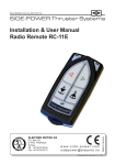
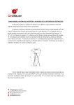
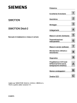
Carlson Software Inc.
www.carlsonsw.com
102 West 2nd Street
Maysville, KY 41056
Phone: (606) 564-5028
Fax: (606) 564-6422
Carlson BRx5 GNSS Receiver Network Rover Quick Start Guide
This Quick Start Guide outlines the steps to follow using SurvCE/SurvPC 4.01 or higher to set up and
configure the BRx5 GNSS receiver as network rover using either the BRx5’s internal GSM modem or the
data collector for communication with the reference network.
Install the Batteries & SIM Card
If you are using the BRx5’s internal GSM modem for communication with the reference network, you
will need to install the GSM SIM card at the same time you install the battery. The SIM card is accessible
by removing the right hand (marked SIM) battery tray
Before configuring the BRx5, you will need to install the two batteries in the receiver. To install a
battery:
1. Remove the battery tray by squeezing the
thumb lever down and with your fingers
placed under the lip on the bottom of the
battery tray, pull the battery tray straight out
from Brx5. Some users find it easier to turn
the BRx5 upside down and use their fingers to
pull the battery tray release lever up while
hooking their thumb on the battery tray lip
and pulling the tray straight out.
2. If there was already a battery installed, remove it
from the tray.
3. Insert the new (charged) battery into the battery tray
making sure the end of the battery with the leads (on top) points
away from the tray as shown below.
4. Replace the tray, making sure the tray snaps into place. Repeat this
process for the other battery tray.
When you have removed the right battery tray (marked SIM on the front), insert the SIM card into the
BRx5 as follows:
1. Place the BRx5 upside down (on its top) to get a better view of the card as shown below.
This document contains confidential and proprietary information that remains the property of Carlson Software Inc.
Page 1 of 6
Updated 12/22/2014
Carlson Software Inc.
www.carlsonsw.com
102 West 2nd Street
Maysville, KY 41056
Phone: (606) 564-5028
Fax: (606) 564-6422
Note: When you insert either the SIM card or an SD memory card make sure the contacts on the card
are facing the top of the unit and the side of the card with the notch goes in first (see figure above).
2. Place the card in the SIM card slot, oriented as shown above.
3. Gently push the card in until it clicks.
4. Replace the battery and battery tray.
Powering the BRx5 On and Off
Power On: Press and hold the Power button until the S320 powers up (until you hear one beep).
Power Off: Press and hold the Power button for 3 seconds (until you hear three beeps or see the
External Power Status LED (#4) flash).
Note: When you power on the BRx5 the LEDs go through a ‘heartbeat’ sequence; during this time the
modules power up and the devices initialize.
Network Rover Setup
1) Power on just the Rover receiver by holding the power button until the lights show on the front
then release it.
2) Run SurvCE/SurvPC 4.01 or higher on your data collector and
go into Equip / GPS Rover menu selection.
3) Set the current tab to Manufacturer: Carlson and Model: BRx5
4) Tap the Comms tab and set it to Type: Bluetooth and tap the
“wrenches” icon next to “BT Type: Windows Mobile”
This document contains confidential and proprietary information that remains the property of Carlson Software Inc.
Page 2 of 6
Updated 12/22/2014
Carlson Software Inc.
www.carlsonsw.com
102 West 2nd Street
Maysville, KY 41056
Phone: (606) 564-5028
Fax: (606) 564-6422
5) Tap “Find Device” and tap on “HGPS S320 xxxxxxx” (xxxxxxx is the serial number of the BRx5 and
can be found on the bottom on the receiver if you need to verify it) to highlight it and then tap
Green Check.
6) Tap the Green Check again to use “Any Available Port”
7) Tap the Bluetooth icon in the top Right to bond to the Rover
Bluetooth. If this is the first time you have paired the data
collector with this BRx5, you will be asked if you want to add
this receiver to your device list. Tap “Yes” to add this receiver
to your device list. Enter “0000” (four zero’s) for the pass
code, if prompted (only prompted the first time you pair the data collector with the BRx5). Tap
Next. Tap Done if notified that the BRx5 was successfully added to the device list.
8) Tap the Receiver tab and type in 6.5617 feet for the 2 meter
fixed height pole (you can also enter 2M for a 2 meter height)
and tap next to “Vertical”.
9) Tap the RTK tab and set Device: to either
o “Internal GSM” if you installed a SIM card in the Brx5
and want to use the BRx5’s internal GSM modem for
communications with the reference network, or
o “Data Collector Internet” to use your data collector for
communication with the reference network.
10) To configure the selected Device (Internal GSM or Data Collector Internet) go to step 11 if your
Device is “Internal GSM”, otherwise go to step 12 for the “Data Collector Internet” instructions.
This document contains confidential and proprietary information that remains the property of Carlson Software Inc.
Page 3 of 6
Updated 12/22/2014
Carlson Software Inc.
www.carlsonsw.com
102 West 2nd Street
Maysville, KY 41056
Phone: (606) 564-5028
Fax: (606) 564-6422
11) For Device: “Internal GSM” tap the “wrenches” to the right
of the device. The Configure Internal GSM window is
displayed. Use the drop-down box to select one of the predefined cellular providers. If your cellular provider is not
listed, select “User”. Tap the “wrenches” icon to display
and edit the APN Settings.
Enter the APN Server Name, the APN User Name and the
APN Password required for your cellular provider. It is
important that the correct values are entered in these
fields. If the BRx5 is not receiving correction data from the
ntrip caster, double check and make sure you have the
correct APN settings for your cellular provider.
12) When using Device: “Data Collector Internet” you typically
establish the internet connection in the data collector
either using WiFi or the data collector’s internal cell modem
prior to running SurvCE. In this case, go to step 13. If you
are using the data collector’s internal cell modem, you can
tap the “wrenches” icon to Configure Data Collector
Internet. Select the ISP profile from the drop-down list.
The entries in this list are the modem connections defined
in the Start/Programs/Setting/Connections/Connections
dialog in the Windows Mobile OS. After selecting the desired ISP, tap the Green Check.
13) Once you have configured the Device, you will need to set the parameters for connecting to the
reference network. Select “NTRIP” in the Network dropdown. (The other options are None,
TCP/IP Direct, UDP/IP Direct and SpiderNet. Please reference the SurvCE user manual for
instructions on using any of these options). Tap the “wrenches” icon to the right of Network.
14) Enter the information required to setup the connection to
the ntrip broadcaster. Name is a name you create to
identify the connection, the name and all associated data
will be available the next time you run SurvCE. The IP
Address is either the URL or the physical IP address of the
ntrip broadcaster. The Port (typically but not necessarily
2101) is the IP port for the ntrip caster data stream. If your
NTRIP broadcaster requires a User Name and Password for
your account, enter them in these fields, otherwise leave
This document contains confidential and proprietary information that remains the property of Carlson Software Inc.
Page 4 of 6
Updated 12/22/2014
Carlson Software Inc.
www.carlsonsw.com
102 West 2nd Street
Maysville, KY 41056
Phone: (606) 564-5028
Fax: (606) 564-6422
them blank. When you have completed, tap the Green check.
15) SurvCE will now connect to the specified NTRIP server and if
successful SurvCE will download the list of base stations
available from the specified NTRIP server. Select the desired
Base ID from the dropdown list. Tap the Green Check.
16) You should now be back in the GPS Rover menu with the RTK tab highlighted. Tap the Green
Check to save your settings and to start receiving corrections from the NTRIP caster. If the BRx5
is configured as “Internal GSM”, the leftmost LED on the BRx5 will be flashing as each RTK
correction data packet is received. If the BRx5 is configured as “Data Collector Internet”, then
the BT LED will be flashing rapidly as RTK correction data is received from the data collector and
the leftmost LED on the control panel will turn Yellow when Float status is achieved and Green
when FIXED status is achieved.
The BRx5 GNSS receiver is now configured as a Network Rover and ready to collect data using SurvCE.
This document contains confidential and proprietary information that remains the property of Carlson Software Inc.
Page 5 of 6
Updated 12/22/2014
Carlson Software Inc.
www.carlsonsw.com
102 West 2nd Street
Maysville, KY 41056
Phone: (606) 564-5028
Fax: (606) 564-6422
The BRx5 control panel overview below describes the LED and buttons in the control panel.
BRx5 Control Panel Overview
Diagram
A
Item
Power button
Name Description
• If unit is Off, press and hold until unit powers up (until you hear one beep)
• If unit is On, press and hold for 3 seconds (until you hear three beeps) to power off the unit
B
Select button
(for Bluetooth/UHF/GSM/SD modules)
Allows you to review module status or change the status (power on/off) of a module
1
UHF/GSM radio
• Off – UHF radio or GSM module is OFF; or no RTK status LED position computed
• On (yellow) – floating point RTK position achieved
• On (green) – fixed ambiguity RTK position achieved
• Blink (green) – UHF radio or GSM module transmitting/receiving data
• Pulse (red) – error condition with UHF radio or GSM Module
2
GPS position
status LED
• Off – no position
• On (yellow) – valid position
• Blink (yellow) – operating as a base station and converging on reference coordinates
3
DGPS position
status LED
• Off – no differential corrections available
• On (green) – differentially corrected position computed
4
External power
status LED
• Off – external power not present
• On (red) – external power present and in use
5 and 6
Battery
status LED
• Off – battery not present
• On (green) – battery charge full
• On (yellow) – battery charge < 50%
• On (red) – battery charge depleted
• Blink – battery in use
7
Bluetooth
status LED
• Off – Bluetooth inactive
• On (blue) – active Bluetooth connection
• Blink (blue) - Bluetooth active and transmitting/receiving data
8
SD logging
status LED
• Off – SD card not inserted
• On (yellow) – SD card inserted, not logging data
• Blink (yellow) - SD card inserted and reading/writing data to SD card
• Pulse (yellow) at 5 Hz - SD card inserted and low free space
AB
This document contains confidential and proprietary information that remains the property of Carlson Software Inc.
Page 6 of 6
Updated 12/22/2014