1
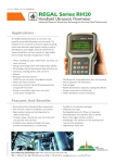
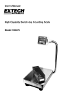
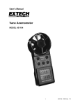
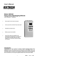
User's Manual
Digital AC Watt Meter
Model 380660
Introduction
Congratulations on your purchase of the Extech 380660 Digital Watt Meter. This 9V
battery-operated meter measures true power up to 6,000 watts on single-phase loads.
AC/DC Current/Voltage measurements can also be made. The color-coded front panel
offers safe and convenient operation. Proper use of this meter will provide years of reliable
service.
Specifications
General Specifications
Display
0.5" (12.7mm), ±1999 count bi-polar LCD Display
Measurements
AC/DC Current/Voltage and AC Watts (true power)
Note: For single phase loads only
Polarity
Positive implied; Negative (reverse) polarity displayed as "-"
Zero Adjust
Manual zero adjust ±30 digits for pow er measurements;
Current and Voltage functions are automatically zeroed
Overload Indication
Indication of "1 " or "-1 "
Operating Temperature 32 to 122oF (0 to 50oC)
Operating Humidity
Less than 80% RH
Environmental conditions Installation: Category II; Pollution: Degree II;
Altitude: 2000 meters; for indoor use only
Power Supply
9V battery; Battery consumption: approx: 6mA
Dimensions / Weight
7.0 x 3.5 x 1.4" (180 x 80 x 35mm) / 1.3 lbs. (538g)
Standard Accessories
Test leads and 9V battery
Optional Accessories
Carrying Case, NIST Certificate
Range Specifications
AC Watt (true power)
Range
Accuracy (FS)
Resolution
2000W
± (1.0% + 1d)
1 Watt
6000W
10 Watts
NOTE: Accuracy for AC Watts applies to signals > 60 VAC (60Hz)
AC/DC Voltage
Range
200V
Accuracy (FS) Resolution Input Impedance Overload protect
± (0.8% + 1d)
600V
0.1V
1MΩ
600V AC/DC
1V
AC/DC Current
Range
10A
Accuracy (FS)
Resolution
Voltage drop (FS current)
± (1% + 1d)
10mA
200mV AC or DC
Notes:
1. Max. Input voltage: 600V AC/DC
2. Max. Input current: 10A AC/DC
3. Frequency range for AC measurements: 45 to 65Hz
4.Accuracy tested with RF field strength <3V/M and <30MHz
5. Converter: Average responding (calibrated to display RMS value of sine wave)
2 Model 380660 Ver. 2.2 February 2001
Meter Description
1.
LCD display
2.
Power ON/OFF switch
3.
Function switches
4.
Input terminals
5.
Zero adjust knob
6.
Battery compartment on rear
Note that the symbol
refers
to AC and DC units.
Safety Information
Precautions
1. Ensure that the 9V battery is properly inserted and that it is fresh.
2. If the LO BAT (low battery) icon appears on the LCD, replace the 9V battery.
3. Press the appropriate Function buttons for the application at hand and insert the test
leads into the proper terminals before connecting the test leads to the circuit under test.
4. Select the proper measurement range by starting at the highest anticipated value.
5. Remove one test lead from the circuit under test when changing the meter's range.
6. If an overload condition occurs (1 or –1 appears on the display), select another
measurement range. If the overload persists, check the meter's function selection and
the connection to the circuit under test before proceeding.
7. Operate the instrument only in the temperature range of 32 to 122oF (0 to 50oC).
8. Do not exceed the maximum rated voltage/current of each range and input terminal.
9. Always switch the power to the "OFF" position when the instrument is not in use.
10. Remove the battery if the instrument is not to be used for a long period of time.
International Safety Symbols
Refer to the manual
for safety details.
Hazardous voltages
may be present.
Double insulation
3 Model 380660 Ver. 2.2 February 2001
Operation
Test Leads
One set of test leads is provided for AC/DC Current/Voltage measurements. However,
when measuring power (watts), two sets of test leads are required as shown below.
Additional leads must be supplied by the user to accommodate the connections required.
Power (Watts) Measurement Connection Diagram
10A
Meter Terminals
COM
V
WATT
Optional 10A Fuse
To 110/220VAC
power source
LOAD
AC Watt (True Power) Measurements
NOTE: Read the safety precautions in the previous section before operating the meter.
1. Ensure that the power to the load is OFF.
2. Slide the meter's power switch to the ON position.
3. Adjust the WATT Zero Adjust Knob until the display indicates "000".
4. Determine the highest anticipated load and select the range that exceeds this value.
5. Connect 110/220VAC power to the "10A" and "WATT" terminals as shown above.
6. Connect the LOAD to the "COM" and "V" terminal as shown above.
7. Apply power to the load.
8. Read the power value in watts on the LCD. In the 6000W range the user must multiply
the displayed reading by 10.
9. Note that during AC Watt measurements, AC voltage or AC current can be measured
by pressing the meter's "ACA" or "ACV" function button.
NOTE: It is recommended that a 10A fuse be placed in series with the LOAD to prevent
damage to the meter in the event of surges or excessive current during Watt (Power) or
Current measurements. Refer to the connection diagram on the previous page.
AC/DC Voltage Measurements
NOTE: Read the safety precautions in the previous section before operating the meter.
1. Connect the BLACK test lead to the "COM" terminal and the RED test lead to the "V"
terminal.
2. Determine highest anticipated DC or AC voltage (200V/600V) and select it on the
corresponding function range button.
3. Slide the power switch to "ON" position.
4. Connect the test leads to the circuit under test.
5. Read the Voltage on the meter's LCD.
4 Model 380660 Ver. 2.2 February 2001
AC/DC Current Measurements
NOTE: Read the safety precautions in the previous section before operating the meter.
1. Connect the BLACK test lead to the "COM" terminal and the RED test lead to the "10A"
terminal.
2. Press the ACA/DCA function switch.
3. Slide the power switch to "ON" position.
4. Connect the test leads in series with the circuit under test.
5. Read the current measurement on the LCD display.
Battery Replacement
When the 'LO BAT' (low battery) icon appears in the left corner of the LCD display, the 9V
battery should be replaced. Accurate measurements may still be made for several hours
after the first appearance of the 'LO BAT' indicator however.
1. Remove the screw that secures the battery compartment cover (rear of meter on
bottom).
2. Slide the battery compartment cover down to access the battery.
3. Replace the 9V battery and reinstall the compartment cover.
Appendix
Power Terms
Term
True (actual) Power
Apparent Power
Power Factor (PF)
Unit
Watts
VA
(ratio)
Formula
Voltage x Current x Power Factor
Voltage x Current
Watts / (Volt x Amps)
Vector Relationship of True/Reactive/Apparent Power and Phase Angle
True Power (Watts)
Ø
Reactive Power (VARS)
Apparent Power (VA)
5 Model 380660 Ver. 2.2 February 2001
Calibration and Repair Services
Extech offers complete repair and calibration services for all of the products we sell.
For periodic calibration, NIST certification or repair of any Extech product, call customer
service for details on services available. Extech recommends that calibration be performed
on an annual basis to insure calibration integrity.
Warranty
EXTECH INSTRUMENTS CORPORATION warrants this instrument to be free of defects
in parts and workmanship for one year from date of shipment (a six month limited
warranty applies on sensors and cables). If it should become necessary to return the
instrument for service during or beyond the warranty period, contact the Customer
Service Department at (781) 890-7440 for authorization. A Return Authorization (RA)
number must be issued before any product is returned to Extech. The sender is
responsible for shipping charges, freight, insurance and proper packaging to prevent
damage in transit. This warranty does not apply to defects resulting from action of the
user such as misuse, improper wiring, operation outside of specification, improper
maintenance or repair, or unauthorized modification. Extech specifically disclaims any
implied warranties or merchantability or fitness for a specific purpose and will not be
liable for any direct, indirect, incidental or consequential damages. Extech's total liability
is limited to repair or replacement of the product. The warranty set forth above is
inclusive and no other warranty, whether written or oral, is expressed or implied.
(
Tech Support Hotlines
781-890-7440 ext. 200
[email protected]
www.extech.com
Copyright © 2001 Extech Instruments Corporation.
All rights reserved including the right of reproduction in whole or in part in any form.
6 Model 380660 Ver. 2.2 February 2001