1
User's Manual
Model 380340
Heavy Duty Datalogging Module
with Windows™ Software
•
Stores data for later recall and analysis
•
Can be used with any Extech Heavy Duty meter
•
Selectable recording interval
•
Battery powered and portable
•
Heavy Duty meters are available for the
measurement of Temperature, Air Velocity and
Flow, Relative Humidity, Light Level, Wood
Moisture, pH, Conductivity, Dissolved Oxygen,
and Pressure
Introduction
Congratulations on your purchase of Extech’s 380340 Datalogging Module. This
professional device, with proper care, will provide years of safe reliable service. The
Datalogger connects to and records data from an Extech Heavy Duty Meter. The sample
rate at which data is recorded is user selectable. Readings stored in the Datalogger can
later be transferred to a PC using the supplied software and communication cables.
1
380340
Ver. 1.6
11/00
Specifications
Input type
Data storage
Display
Adjustable Sample Rate
Internal Clock
Memory Volatility
Batteries
Battery life
Power consumption
Operating temperature
Operating humidity
Weight
Dimensions
RS-232 data stream
8000 readings (16 bit each)
0.5" red 2 digit LED, 100 counts (0-99)
Seconds: 1 to 99, Minutes: 1 to 99, Hours: 1 to 99
Crystal oscillator
Data is retained at power down
Four 1.5V AA (alkaline or heavy duty type)
36 hours continuous (typical)
Approx. 20 to 54 mA DC
32 to 122oF (0 to 50oC)
< 80 % RH
0.45 lbs. (205g) including battery
5.2x2.8x1.0" (131x70x26mm) (HxWxD)
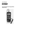
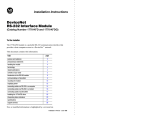
Datalogger Description
1
2
3
4
5
6
7
8
9
10
11
12
13
14
Display
Memory ‘Full’ indicator
‘Data’ indicator
‘Pause’ indicator
‘Power/Low Power’ indicator
‘Auto/Manual/Out’ switch
Sample rate switch
Power ON/Off switch
Reset> / INC 10 button
Pause / INC 1 button
‘Set’ button
‘Data in’ port (meter to Datalogger)
‘Data out’ port (Datalogger to PC)
Battery compartment (rear)
12
13
1
2
3
8
4
5
6
7
11
9
10
14
Datalogging Operation
Note: The Heavy Duty Meters have an Auto-Shutoff feature that will automatically power off
the meter after a fixed time period. This feature should be disabled during a datalogging
session. Press the "RECORD" button on the meter to disable the Auto-Shutoff feature.
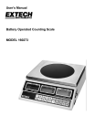
Automated Datalogging Preparation
This function permits the Datalogger to automatically collect readings at the sample rate
set by the user.
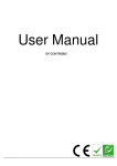
1. Connect the Datalogger's uP IN port to the Heavy Duty Meter as shown in the
illustration below. (The supplied dual 3.5mm cable links the Heavy Duty meter to
the Datalogger).
2. Turn the Datalogger OFF ("0" switch position).
3. Slide the Auto/Man/Out switch to the Auto position.
4. Slide the Time switch to the "S" (seconds), "M"
(minutes) or "H" (hours) position depending on the
data sampling (recording) rate desired (1-99 seconds,
1-99 minutes, or 1-99 hours).
5. If this is the first time the datalogger is being used,
reset (erase) the datalogger's memory per the Reset
Function section below .
6. Power the datalogger ("1" position).
2
380340
Ver. 1.6
11/00
7.
To set the Interval Time (sample rate), press and hold the SET button and, while
holding the SET button, press the INC 1 button to adjust the units digit (use the
"INC 10" button to adjust the tens digit). Release the SET button when complete.
You can set the interval from 1-99 seconds, 1-99 minutes, or 1-99 hours.
Note: If the AUTO or TIME switch is set after turning power on, the datalogger may
misinterpret the switch settings. Always set these switches to the desired setting
before powering the Datalogger.
Begin Automated Datalogging
1.
2.
3.
Press the PAUSE button to begin logging measurements. The PAUSE LED will
extinguish and the DATA LED will blink each time a measurement is recorded.
Press the PAUSE button a second time to pause datalogging (PAUSE LED lights).
Each time PAUSE is pressed datalogging will toggle ON (resume) and OFF
(pause). When datalogging is resumed, the new data are written starting where the
existing data left off so that existing data are retained.
RESET function
The RESET function sets the Datalogger to begin recording new data starting at record
number one..
1. Connect the datalogger to the meter as previously described.
2. Set the Auto/Man/Out switch to either the AUTO or MAN position.
3. Power the datalogger and the meter.
4. Press and hold the RESET button for approx. 4 seconds, until "00" is displayed.
NOTE: It may take several RESETS to clear all the datalogger memory levels. To be
sure, repeat the RESET procedure 2-3 times in succession.
NOTE: The RESET function moves the data pointer to the first record in the memory.
Data actually remains intact until a new recording session begins
FULL indicator
The FULL indicator lights when 7999 data points have been recorded.
NOTE: Data will remain in memory until the Datalogger is RESET or until the batteries
become weak.
Manual Datalogging
Manual datalogging allows the user to record one reading at a time.
1. Turn the Datalogger OFF ("0" switch position).
2. Slide the Auto/Man/Out switch to the MAN position.
3. Power the Datalogger ("1" position). If the MAN switch is set after turning power on,
the Datalogger may misinterpret the switch settings.
4. Press the PAUSE button to log one measurement.
5. When the Datalogger memory is full, the FULL indicator will light.
6. To clear (RESET) the Datalogger memory, refer to the Reset Function section
above.
Transferring Data to a PC
Once data is collected, the next step is to connect the Datalogger to a PC and download
the collected readings.
Hardware Connection
Using the supplied 3.5mm to DB-9 cable, connect
the Datalogger’s uP OUT port to the PC COM
port as shown in the illustration at right.
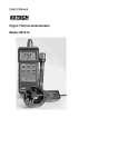
The supplied WindowsTM 95/98 Datalogger Software
Install the software from the WindowsT M program
disks (two supplied) and run the D19601W.exe
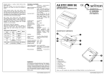
file. The following software screen will appear.
3
380340
Ver. 1.6
11/00
Software Screen Description
1. COM Port Selection (Click on appropriate port, COM1 or COM2)
2. Data Transfer Status (informs the users as to status of data transfer)
3. Transferred Data View
4. Data File Name (type desired filename)
5. Number of Data points
6. Instructional steps describing the data transfer process. More detailed steps are
listed below in the next section.
7. Function buttons: START (click to begin data transfer); VIEW DATA (click to see all
transferred data as shown in item 3 above), and EXIT (click to close program)
Begin Data Transfer
To transfer data from a Heavy Duty meter to a PC, follow the instructions shown below:
1. Slide the Auto/Man/Out Datalogger switch to the OUT position.
2. Power the Datalogger.
3. Select COM 1 or COM 2 on the software screen.
4. Type a file name in the Data File Name field on the software screen.
5. Click on the START key in the software window
6. Press the RESET button on the Datalogger to begin the data transfer.
7. The DATA LED will rapidly blink as the data transfer takes place.
8. Press the PAUSE button to halt the transfer.
9. When the Data LED ceases blinking, the data points have been transferred.
10. After the data points have been transferred, turn off the datalogger. Data will
remain in the datalogger as long as the batteries are fresh.
The data points are transferred to the PC file named in step 2 above in the Software
Screen Description section. To view the transferred data, click the VIEW DATA key on
the software screen. The transferred data will appear as shown above in item 3 of the
diagram. The data file stored on the PC can now be opened in other applications such
as spreadsheet, word-processor, database, etc.
4
380340
Ver. 1.6
11/00
Model 407000 Software
The 407000 software and cable connects any Heavy Duty meter to a PC for data display
and collection directly into the PC. The software also contains a utility that can download
data from the Datalogger. Refer to the 407000 manual for details or contact Extech.
Battery Replacement
When the "GOOD / LO BAT" LED indicator is NOT illuminated the batteries should be
replaced. Slide the rear battery cover off in the direction of the arrow. Replace the four AA
batteries. Check for proper battery polarity when inserting.
Calibration and Repair Services
Extech offers complete repair and calibration services for all of the products we sell. For
periodic calibration, NIST certification or repair of any Extech product, call customer
service for details on services available. Extech recommends that calibration be performed
on an annual basis to insure calibration integrity.
Warranty
EXTECH INSTRUMENTS CORPORATION warrants this instrument to be free of defects in parts and
workmanship for one year from date of shipment (a six month limited warranty applies on sensors and
cables). If it should become necessary to return the instrument for service during or beyond the warranty
period, contact the Customer Service Department at (781) 890-7440 for authorization. A Return
Authorization (RA) number must be issued before any product is returned to Extech. The sender is
responsible for shipping charges, freight, insurance and proper packaging to prevent damage in transit.
This warranty does not apply to defects resulting from action of the user such as misuse, improper wiring,
operation outside of specification, improper maintenance or repair, or unauthorized modification. Extech
specifically disclaims any implied warranties or merchantability or fitness for a specific purpose and will not
be liable for any direct, indirect, incidental or consequential damages. Extech's total liability is limited to
repair or replacement of the product. The warranty set forth above is inclusive and no other warranty,
whether written or oral, is expressed or implied.
Copyright © 2000 Extech Instruments Corporation. All rights reserved including
the right of reproduction in whole or in part in any form.
(
Tech Support Hotlines
781-890-7440 ext. 200
[email protected]
www.extech.com
5
380340
Ver. 1.6
11/00