1
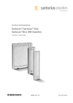
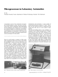
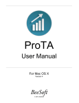
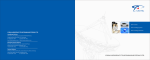
MICRO-STAR INTERNATIONAL.CO.,LTD EC DECLARATION OF CONFORMITY Bluetooth 2.0+EDR USB module MS-6837D MICRO-STAR INT’L CO., LTD NO.69,LI-DE ST,JUNG-HE CITY , TAIPEI HSIEN, TAIWAN 886-2-3234-5599 886-2-3234-5416 Product : Type Designation : Manufacturer : Address : TEL FAX ‘ : : The Designed product is in conformity with European Directive 73/23/EEC including amandements “Council Directive of 19 February 1973 on the harmonization of the laws of the members relating to electrical equipment designed for use within certain voltage limits” Full compliance with the standards listed below proves the conformity of the designated product with the provisions of the above-mentioned EC Directive EN 60950-1:2001 File reference : 20060323-1 Year of CE marking:2006 Responsible for making this declaration is the: Manufacturer □ Authorized representative established within the EU □ Authorized representative established within the EU(if applicable): Company name : Company address : Person responsible for making this declaration Name,Surname : Dessy Li Position :Safety Engineer Taiwan (place) MICRO-STAR INT’CO,.LTD TEL : 886-2-3234-5599 FAX : 886-2-3234-5416 March23,2006 (date) (company stamp and Legal signature) Test Report No.: Model / type designation : Rating(s): Standards: Applicant Name and Address: Factory Location(s): 20060323-1 MS-6837D / Bluetooth 2.0+EDR USB module 5 Vdc,60mA EN 60950-1 MICRO-STAR INTERNATIONAL CO LTD 69 LI-DE ST CHUNG HO 235 TAIWAN MSI ELECTRONICS (KUNSHAN) CO LTD 88 E QUANJIN RD KUNSHAN CITY ,JIANGSU 215300 CHINA MSI COMPUTER (SHENZHEN) CO LTD LONGMA INFORMATION TECHNOLOGY IND PARK TANGTOU VILLAGE, SHIYAN TOWN BAO'AN DISTRICT SHENZHEN GUANGDONG, CHINA MICRO-STAR INTERNATIONAL CO., LTD 488 BAN NAN ST CHUNG HO CITY TAIPEI HSIEN 235, TAIWAN STAR ELECTRONICS (KUNSHAN) CO LTD 66 E QIANJIN RD KUNSHAN CITY JIANGSU 215300, CHINA Test by : Reviewed by: signature Signature Other Aspect: The completed test report includes the following documents: EN 60950-1 report Abbreviations: Pass =passed Fail =failed N/A =not applicable This test report relates to the following test report conducted by MSI engineer. Without Permission of the MSI is not permitted to be duplicated in extracts. This test report doesn’t entitle to carry any safety mark on this or similar products MICRO-STAR INT’L CO.,LTD TEL : 886-2-3234-5599 FAX : 886-2-3234-5416 ISSUED DATE :2006/03/23 \ PAGE : 1 TEST REPORT EN 60950-1 Information Technology Equipment - Safety Report Reference No ......... : 20060323-1 Compiled by (+ signature)...... : Daphne Cheng Reviewed by (+ signature) ..... : Dessy Li Date of issue..................................... : See cover sheet Test Place/Location ................. : Micro-Star Int’l Co.,LTD Address............................................. : No.69,Li-De Street,Jung-Ho City,Taipei Hsien,Taiwan Applicant's Name .......................... : MICRO-STAR INTERNATIONAL CO LTD 69 LI-DE ST Address ........................................... : JUNG- HO CITY 235 TAIWAN Test specification: Standard .......................................... : EN 60950-1:2001 Test procedure : Service of CE Marking in LVD Procedure Deviation………………….: N/A Non-standard test method .............. : N/A Type of test object ............................ : Bluetooth 2.0+EDR USB module Model /Type reference...................... : MS-6837D Manufacturer..................................... : Same as applicant Micro-Star Int’l Co.,Ltd Rating ………………………: 5 Vdc Test item particular : Equipment mobility……………: Built-in equipment Operation condition…………..: Continuous Test for IT power system…….: No IT testing ,phase-phase voltage (V)..: N/A Class of equipment………………….: Class III Mass of Equipment…………………..: < 1Kg MICRO-STAR INT’L CO.,LTD TEL : 886-2-3234-5599 FAX : 886-2-3234-5416 ISSUED DATE :2006/03/23 \ PAGE : 2 Protection against ingress of water…: IP20 Possible test case verdicts…………: -test case doesn’t apply to the object…………:N/A - test object doesn’t meet the requirement……:PASS - test object does not meet the requirement….:FAIL “(see remark #)”refer to a remark appended to the report “(see remark #)”refers to an annex appended to the report A point is used as the decimal separator in this report The test result presented in this report only related to the object tested This report shall not be reproduced without full written approval from Micro-Star Int’l Co.,LTD General Product information: Product description: - Those equipment models MS-6837D is Bluetooth module that built-in the Notebook for information technology equipment Maximum operation ambient 70 degree C Additional Information : Comments: N/A Copy of Marking Plate: MICRO-STAR INT’L CO.,LTD TEL : 886-2-3234-5599 FAX : 886-2-3234-5416 ISSUED DATE :2006/03/23 \ PAGE : 3 1 GENERAL Pass 1.5 Components Pass 1.5.1 General Pass 1.5.2 Comply with IEC 60950 or relevant component standard (See appended table 1.5.1) Pass Evaluation and testing of components Certified components are used in accordance with their ratings, certifications and they comply with applicable parts of this Standard. Components not certified are used in accordance with their ratings and they comply with applicable parts of IEC 60950 and the relevant component Standard. Pass Components, for which no relevant IEC Standard exist, have been tested under the conditions occurring in the equipment, using applicable parts of IEC 60950. 1.5.3 Thermal controls 1.5.4 Transformers Evaluated as part of power supply. 1.5.5 Interconnecting cables USB cable for signal connected to PC or Notebook is carrying only SELV on an energy level below 240VA 1.5.6 Capacitors in primary circuits ...................: Evaluated as part of power N/A 1.5.7 Double insulation or reinforced insulation bridged by components N/A 1.5.7.1 General N/A 1.5.7.2 Bridging capacitors N/A 1.5.7.3 Bridging resistors N/A 1.5.7.4 Accessible parts N/A 1.5.8 Components in equipment for IT power systems N/A supply. MICRO-STAR INT’L CO.,LTD TEL : 886-2-3234-5599 FAX : 886-2-3234-5416 Evaluated as part of power supply. Equipment is not connected directly connected to the AC mains supply ISSUED DATE :2006/03/23 \ PAGE : 4 N/A Pass N/A 1.6 Power interface 1.6.1 AC power distribution systems Equipment is not connected directly connected to the AC mains supply N/A 1.6.2 Input current The equipment was built-in equipment ,so estimate in finishing product N/A 1.6.3 Voltage limit of hand-held equipment N/A 1.6.4 Neutral conductor N/A 1.7 Marking and instructions 1.7.1 Power rating Pass Pass See Below Pass Rated voltage(s) or voltage range(s) (V)........................ : 5Vdc N/A Symbol for nature of supply, for d.c. only....................... : No direct connection to AC mains supply N/A Rated frequency or rated frequency range (Hz) ............ : DC only Pass Rated current (mA or A) ................................................. : 60mA Pass Manufacturer's name or trademark or identification mark: Micro-Star International Co., Ltd. / MSI Pass Type/model or type reference ........................................ : Bluetooth 2.0+EDR USB Pass module / MS-6837D Symbol for Class II equipment only ............................... : Unit is Class III N/A Other symbols ............................................................... : Additional symbols may be provided when submitted for National Approval. Pass Certification marks ......................................................... : See copy of marking plate Pass 1.7.2 Safety instructions Pass 1.7.3 Short duty cycles N/A 1.7.4 Supply voltage adjustment............................................. : No voltage/frequency setting N/A 1.7.5 Power outlets on the equipment .................................... : N/A 1.7.6 Fuse identification.......................................................... : No fuse N/A 1.7.7 Wiring terminals N/A 1.7.7.1 Protective earthing and bonding terminals..................... : No direct connection to AC mains supply N/A 1.7.7.2 Terminal for a.c. mains supply conductors No direct connection to AC mains supply N/A 1.7.7.3 Terminals for d.c. mains supply conductors No DC mains supply N/A MICRO-STAR INT’L CO.,LTD TEL : 886-2-3234-5599 FAX : 886-2-3234-5416 Operating/safety instructions made available to the user. ISSUED DATE :2006/03/23 \ PAGE : 5 1.7.8 Controls and indicators No safety relavant switch or control 1.7.8.1 Identification, location and marking ............................... : N/A 1.7.8.2 Colours .......................................................................... : N/A 1.7.8.3 Symbols according to IEC 60417 .................................. : . N/A 1.7.8.4 Markings using figures................................................... : No indicatiors for different positions N/A 1.7.9 Isolation of multiple power sources................................ : Class III equipment. No supply to main N/A 1.7.10 IT power distribution systems Class III equipment. No supply to main N/A 1.7.11 Thermostats and other regulating devices No adjustable thermostats N/A 1.7.12 Language....................................................................... : May be provided in other languages upon request from the manufacturer. User manual and marking label are in english 1.7.13 Durability The marking(s) withstood the required test. 1.7.14 Removable parts No required marking placed on moveable part N/A 1.7.15 Replaceable batteries No replaceable batteries provided N/A Language ...............................................................: N/A P Pass - 1.7.16 Operator access with a tool....................................: No operator access area with tool N/A 1.7.17 Equipment for restricted access locations .............: No restricted access location N/A 2 PROTECTION FROM HAZARDS Pass 2.1 Protection from electric shock and energy hazards Pass 2.1.1 Protection in operator access areas See below 2.1.1.1 Access to energized parts No energized parts Pass N/A Test by inspection...................................................: Dto N/A Test with test finger ................................................: Dto N/A Test with test pin.....................................................: Dto N/A Test with test probe ................................................: no TNV circuit N/A 2.1.1.2 Battery compartments ............................................: N/A 2.1.1.3 Access to ELV wiring MICRO-STAR INT’L CO.,LTD TEL : 886-2-3234-5599 FAX : 886-2-3234-5416 No ELV wiring in operator ISSUED DATE :2006/03/23 \ PAGE : 6 N/A accessible area Working voltage (V); minimum distance (mm) through insulation ...................................................: - 2.1.1.4 Access to hazardous voltage circuit wiring No hazardous voltage wiring in operator accessible area 2.1.1.5 Energy hazards ......................................................: No energy hazard operator area 2.1.1.6 Manual controls 2.1.1.7 Discharge of capacitors in equipment No manual control N/A Pass N/A N/A Time-constant (s); measured voltage (V) ...............: - 2.1.2 Protection in service access areas 2.1.3 Protection in restricted access locations 2.2 SELV circuits 2.2.1 General requirements 2.2.2 Voltages under normal conditions (V) ......: All accessible voltages are Pass 2.2.3 Voltages under fault conditions (V)...........: Under fault conditions voltage Pass 2.2.3.1 Separation by double insulation or reinforced insulation (method 1) 2.2.3.2 Separation by earthed screen (method 2) N/A 2.2.3.3 Protection by earthing of the SELV circuit (method 3) N/A 2.2.4 Connection of SELV circuits to other circuits .........: The SELV circuits are not connected to circuits other than protective earth and other SELV circuits. 2.3 TNV circuits N/A 2.3.1 Limits N/A N/A It’s not intended to be used in restricted locations Pass The secondary circuits were tested as SELV. less than 42.4 Vp or 60 V dc and are classified as SELV. never exceed 71 Vp and 120 Vdc and do not exceed 42.4 Vp or 60 Vdc for more than 0.2 sec. Evaluated as part of power supply. Type of TNV circuits .................................: MICRO-STAR INT’L CO.,LTD TEL : 886-2-3234-5599 FAX : 886-2-3234-5416 N/A Pass N/A Pass - ISSUED DATE :2006/03/23 \ PAGE : 7 2.3.2 2.3.3 Separation from other circuits and from accessible parts N/A Insulation employed .................................: - Separation from hazardous voltages N/A Insulation employed .................................: 2.3.4 - Connection of TNV circuits to other circuits N/A Insulation employed .................................: - 2.3.5 Test for operating voltages generated externally N/A 2.4 Limited current circuits N/A 2.4.1 General requirements N/A 2.4.2 Limit values N/A Frequency (Hz) ........................................: - Measured current (mA) ............................: - Measured voltage (V) ...............................: - Measured capacitance (mF).....................: - 2.4.3 Connection of limited current circuits to other circuits N/A 2.5 Limited power sources N/A Inherently limited output N/A Impedance limited output N/A Overcurrent protective device limited output N/A Regulating network limited output under normal operating and single fault condition N/A Regulating network limited output under normal operating conditions and overcurrent protective device limited output under single fault condition N/A Output voltage (V), output current (A), apparent power (VA): : - Current rating of overcurrent protective device (A) : - 2.6 Provisions for earthing and bonding Class III equipment MICRO-STAR INT’L CO.,LTD TEL : 886-2-3234-5599 FAX : 886-2-3234-5416 N/A ISSUED DATE :2006/03/23 \ PAGE : 8 2.6.1 Protective earthing N/A 2.6.2 Functional earthing N/A 2.6.3 Protective earthing and protective bonding conductors N/A 2.6.3.1 General N/A 2.6.3.2 Size of protective earthing conductors N/A Rated current (A), cross-sectional area (mm2), AWG .......................................................................: 2.6.3.3 - Size of protective bonding conductors N/A Rated current (A), cross-sectional area (mm2), AWG .......................................................................: - 2.6.3.4 Resistance (Ohm) of earthing conductors and their terminations, test current (A)..................................: N/A 2.6.3.5 Colour of insulation.................................................: N/A 2.6.4 Terminals N/A 2.6.4.1 General N/A 2.6.4.2 Protective earthing and bonding terminals N/A Rated current (A), type and nominal thread diameter (mm) ........................................................: - 2.6.4.3 Separation of the protective earthing conductor from protective bonding conductors N/A 2.6.5 Integrity of protective earthing N/A 2.6.5.1 Interconnection of equipment N/A 2.6.5.2 Components in protective earthing conductors and protective bonding conductors N/A 2.6.5.3 Disconnection of protective earth N/A 2.6.5.4 Parts that can be removed by an operator N/A 2.6.5.5 Parts removed during servicing N/A 2.6.5.6 Corrosion resistance N/A 2.6.5.7 Screws for protective bonding N/A 2.6.5.8 Reliance on telecommunication network or cable distribution system N/A 2.7 Overcurrent and earth fault protection in primary circuits N/A 2.7.1 Basic requirements N/A MICRO-STAR INT’L CO.,LTD TEL : 886-2-3234-5599 FAX : 886-2-3234-5416 ISSUED DATE :2006/03/23 \ PAGE : 9 Instructions when protection relies on building installation N/A 2.7.2 Faults not covered in 5.3 N/A 2.7.3 Short-circuit backup protection N/A 2.7.4 Number and location of protective devices ............: N/A 2.7.5 Protection by several devices N/A 2.7.6 Warning to service personnel.................................: N/A 2.8 Safety interlocks N/A 2.8.1 General principles N/A 2.8.2 Protection requirements N/A 2.8.3 Inadvertent reactivation N/A 2.8.4 Fail-safe operation N/A 2.8.5 Moving parts N/A 2.8.6 Overriding N/A 2.8.7 Switches and relays N/A 2.8.7.1 Contact gaps (mm).................................................: N/A 2.8.7.2 Overload test N/A 2.8.7.3 Endurance test N/A 2.8.7.4 Electric strength test N/A 2.8.8 Mechanical actuators N/A 2.9 Electrical insulation N/A 2.9.1 Properties of insulating materials N/A 2.9.2 Humidity conditioning N/A Humidity (%)...........................................................: - Temperature (°C)....................................................: - 2.9.3 Grade of insulation N/A 2.10 Clearances, creepage distances and distances through insulation Class III equipment N/A 2.10.1 General N/A 2.10.2 Determination of working voltage N/A MICRO-STAR INT’L CO.,LTD TEL : 886-2-3234-5599 FAX : 886-2-3234-5416 ISSUED DATE :2006/03/23 \ PAGE : 10 2.10.3 Clearances N/A 2.10.3.1 General N/A 2.10.3.2 Clearances in primary circuit N/A 2.10.3.3 Clearances in secondary circuits N/A 2.10.3.4 Measurement of transient voltage levels N/A 2.10.4 Creepage distances N/A CTI tests .................................................................: - 2.10.5 Solid insulation N/A 2.10.5.1 Minimum distance through insulation N/A 2.10.5.2 Thin sheet material N/A 2.10.5.3 Number of layers (pcs)...........................................: - Electric strength test...............................................: - Printed boards N/A Distance through insulation N/A Electric strength test for thin sheet insulating material...................................................................: - Number of layers (pcs)...........................................: N/A Wound components N/A Number of layers (pcs)...........................................: N/A Two wires in contact inside wound component; angle between 45° and 90° ....................................: N/A 2.10.6 Coated printed boards N/A 2.10.6.1 General N/A 2.10.6.2 Sample preparation and preliminary inspection N/A 2.10.6.3 Thermal cycling N/A 2.10.6.4 Thermal ageing (°C)...............................................: N/A 2.10.6.5 Electric strength test...............................................: - 2.10.6.6 Abrasion resistance test 2.10.5.4 2.10.7 2.10.8 N/A Electric strength test...............................................: - Enclosed and sealed parts .....................................: N/A Temperature T1=T2 = Tma - Tamb +10K (°C) .......: N/A Spacings filled by insulating compound .................: N/A Electric strength test...............................................: - MICRO-STAR INT’L CO.,LTD TEL : 886-2-3234-5599 FAX : 886-2-3234-5416 ISSUED DATE :2006/03/23 \ PAGE : 11 2.10.9 Component external terminations N/A 2.10.10 Insulation with varying dimensions N/A 3 WIRING, CONNECTIONS AND SUPPLY Pass 3.1 General Pass 3.1.1 Current rating and overcurrent protection N/A 3.1.2 Protection against mechanical damage N/A 3.1.3 Securing of internal wiring N/A 3.1.4 Insulation of conductors N/A 3.1.5 Beads and ceramic insulators Not used N/A 3.1.6 Screws for electrical contact pressure No such screw N/A 3.1.7 Insulating materials in electrical connections 3.1.8 Self-tapping and spaced thread screws 3.1.9 Termination of conductors N/A 10 N pull test N/A N/A No self-tapping or spaced thread screws used Not used N/A 3.1.10 Sleeving on wiring 3.2 Connection to an a.c. mains supply or a d.c. mains supply Class III equipment N/A 3.2.1 Means of connection N/A 3.2.1.1 Connection to an a.c. mains supply N/A 3.2.1.2 Connection to a d.c. mains supply N/A 3.2.2 Multiple supply connections N/A 3.2.3 Permanently connected equipment N/A N/A Number of conductors, diameter (mm) of cable and conduits ..................................................................: - 3.2.4 Appliance inlets N/A 3.2.5 Power supply cords N/A 3.2.5.1 AC power supply cords N/A Type........................................................................: - Rated current (A), cross-sectional area (mm²), AWG .......................................................................: - MICRO-STAR INT’L CO.,LTD TEL : 886-2-3234-5599 FAX : 886-2-3234-5416 ISSUED DATE :2006/03/23 \ PAGE : 12 3.2.5.2 DC power supply cords N/A 3.2.6 Cord anchorages and strain relief N/A Mass of equipment (kg), pull (N) ............................: - Longitudinal displacement (mm) ............................: - 3.2.7 Protection against mechanical damage N/A 3.2.8 Cord guards N/A D (mm); test mass (g) ............................................: - Radius of curvature of cord (mm)...........................: - 3.2.9 Supply wiring space N/A 3.3 Wiring terminals for connection of external conductors N/A 3.3.1 Wiring terminals N/A 3.3.2 Connection of non-detachable power supply cords N/A 3.3.3 Screw terminals N/A 3.3.4 Conductor sizes to be connected N/A Rated current (A), cord/cable type, cross-sectional area (mm²)..............................................................: 3.3.5 - Wiring terminal sizes N/A Rated current (A), type and nominal thread diameter (mm) ........................................................: - 3.3.6 Wiring terminals design N/A 3.3.7 Grouping of wiring terminals N/A 3.3.8 Stranded wire N/A 3.4 Disconnection from the mains supply N/A 3.4.1 General requirement N/A 3.4.2 Disconnect devices N/A 3.4.3 Permanently connected equipment N/A 3.4.4 Parts which remain energized N/A 3.4.5 Switches in flexible cords N/A 3.4.6 Single-phase equipment and d.c. equipment N/A 3.4.7 Three-phase equipment N/A MICRO-STAR INT’L CO.,LTD TEL : 886-2-3234-5599 FAX : 886-2-3234-5416 ISSUED DATE :2006/03/23 \ PAGE : 13 3.4.8 Switches as disconnect devices N/A 3.4.9 Plugs as disconnect devices N/A 3.4.10 Interconnected equipment N/A 3.4.11 Multiple power sources N/A 3.5 Interconnection of equipment N/A 3.5.1 General requirements 3.5.2 Types of interconnection circuits ............................: 3.5.3 ELV circuits as interconnection circuits 4 PHYSICAL REQUIREMENTS 4.1 Stability See below N/A N/A No ELV interconnection N/A N/A N/A Angle of 10° N/A Test: force (N).........................................................: N/A 4.2 Mechanical strength N/A 4.2.1 General N/A 4.2.2 Steady force test, 10 N N/A 4.2.3 Steady force test, 30 N N/A 4.2.4 Steady force test, 250 N N/A 4.2.5 Impact test N/A Fall test N/A Swing test N/A 4.2.6 Drop test N/A 4.2.7 Stress relief test N/A 4.2.8 Cathode ray tubes N/A Picture tube separately certified.............................: N/A 4.2.9 High pressure lamps N/A 4.2.10 Wall or ceiling mounted equipment; force (N) ........: N/A MICRO-STAR INT’L CO.,LTD TEL : 886-2-3234-5599 FAX : 886-2-3234-5416 ISSUED DATE :2006/03/23 \ PAGE : 14 4.3 Design and construction 4.3.1 Edges and corners N/A 4.3.2 Handles and manual controls; force (N)...: N/A 4.3.3 Adjustable controls N/a 4.3.4 Securing of parts N/A 4.3.5 Connection of plugs and sockets N/A 4.3.6 Direct plug-in equipment N/A Dimensions (mm) of mains plug for direct plug-in..: N/A Torque and pull test of mains plug for direct plug-in; torque (Nm); pull (N) ..............................................: N/A Pass 4.3.7 Heating elements in earthed equipment No heating element 4.3.8 Batteries 4.3.9 Oil and grease 4.3.10 Dust, powders, liquids and gases N/A 4.3.11 Containers for liquids or gases N/A 4.3.12 Flammable liquids ..................................................: No flammable fluid N/A Quantity of liquid (l) ................................................: N/A Flash point (°C) ......................................................: N/A 4.3.13 Radiation; type of radiation N/A 4.3.13.1 General N/A 4.3.13.2 Ionizing radiation N/A N/A N/A No oil or grease N/A Measured radiation (pA/kg)....................................: - Measured high-voltage (kV) ...................................: - Measured focus voltage (kV) .................................: - CRT markings.........................................................: - Effect of ultraviolet (UV) radiation on materials N/A Part, property, retention after test, flammability classification ...........................................................: N/A 4.3.13.4 Human exposure to ultraviolet (UV) radiation ........: N/A 4.3.13.5 Laser (including LEDs) N/A 4.3.13.3 4.3.13.6 Laser class .............................................................: - Other types...............................................: N/A MICRO-STAR INT’L CO.,LTD TEL : 886-2-3234-5599 FAX : 886-2-3234-5416 ISSUED DATE :2006/03/23 \ PAGE : 15 4.4 Protection against hazardous moving parts N/A 4.4.1 General N/A 4.4.2 Protection in operator access areas N/A 4.4.3 Protection in restricted access locations N/A 4.4.4 Protection in service access areas N/A 4.5 Thermal requirements N/A 4.5.1 Maximum temperatures N/A Normal load condition per Annex L ..........: N/A 4.5.2 Resistance to abnormal heat N/A 4.6 Openings in enclosures The equipment was built-in equipment N/A 4.6.1 Top and side openings No openings N/A Dimensions (mm) ...................................................: . 4.6.2 Bottoms of fire enclosures - No openings. N/A Construction of the bottom .....................................: 4.6.3 Doors or covers in fire enclosures 4.6.4 Openings in transportable equipment 4.6.5 Adhesives for constructional purposes N/A No openings N/A N/A Conditioning temperature (°C)/time (weeks) ....................................................: - 4.7 Resistance to fire 4.7.1 Reducing the risk of ignition and spread of flame Use of materials with the required flammability classes 4.7.2 Conditions for a fire enclosure Built-in equipment N/A 4.7.2.1 Parts requiring a fire enclosure Built-in equipment N/A 4.7.2.2 Parts not requiring a fire enclosure 4.7.3 Materials 4.7.3.1 General PCB rated V-1 or better 4.7.3.2 Materials for fire enclosures See 4.7.2.1 MICRO-STAR INT’L CO.,LTD TEL : 886-2-3234-5599 FAX : 886-2-3234-5416 Pass Pass N/A Pass N/A ISSUED DATE :2006/03/23 \ Pass PAGE : 16 4.7.3.3 Materials for components and other parts outside fire enclosures 4.7.3.4 Materials for components and other parts inside fire Internal part components enclosures except small parts are V-2 ,HF-2 or better 4.7.3.5 Materials for air filter assemblies N/A 4.7.3.6 Materials used in high-voltage components N/A 5 ELECTRICAL REQUIREMENTS AND SIMULATED ABNORMAL CONDITIONS N/A 5.1 Touch current and protective conductor current N/A 5.1.1 General N/A 5.1.2 Equipment under test (EUT) N/A 5.1.3 Test circuit N/A 5.1.4 Application of measuring instrument N/A 5.1.5 Test procedure N/A 5.1.6 Test measurements N/A N/A Pass Test voltage (V) ......................................................: - Measured touch current (mA) ................................: - Max. allowed touch current (mA) ...........................: 3 - Measured protective conductor current (mA).........: - Max. allowed protective conductor current (mA)....: - 5.1.7 Equipment with touch current exceeding 3.5 mA...: N/A 5.1.8 Touch currents to and from telecommunication networks and cable distribution systems and from telecommunication networks No TNV circuit N/A 5.1.8.1 No TNV circuit Limitation of the touch current to a telecommunication network and a cable distribution system N/A Test voltage (V) ......................................................: - Measured touch current (mA) ................................: - Max. allowed touch current (mA) ...........................: - 5.1.8.2 Summation of touch currents from telecommunication networks..................................: N/A 5.2 Electric strength N/A MICRO-STAR INT’L CO.,LTD TEL : 886-2-3234-5599 FAX : 886-2-3234-5416 ISSUED DATE :2006/03/23 \ PAGE : 17 Class III equipment 5.2.1 General N/A 5.2.2 Test procedure N/A 5.3 Abnormal operating and fault conditions N/A 5.3.1 Protection against overload and abnormal operation N/A 5.3.2 Motors 5.3.3 Transformers N/A 5.3.4 Functional insulation ..............................................: N/A 5.3.5 Electromechanical components N/A 5.3.6 Simulation of faults N/A 5.3.7 Unattended equipment N/A 5.3.8 Compliance criteria for abnormal operating and fault conditions N/A 6 CONNECTION TO TELECOMMUNICATION NETWORKS N/A 6.1 Protection of telecommunication network service persons, and users of other equipment connected to the network, from hazards in the equipment N/A 6.1.1 Protection from hazardous voltages N/A 6.1.2 Separation of the telecommunication network from earth N/A 6.1.2.1 Requirements N/A . N/A Test voltage (V) ........................................: - Current in the test circuit (mA)..................: - 6.1.2.2 Exclusions ................................................: N/A 6.2 Protection of equipment users from overvoltages on telecommunication networks N/A 6.2.1 Separation requirements N/A 6.2.2 Electric strength test procedure N/A 6.2.2.1 Impulse test N/A 6.2.2.2 Steady-state test N/A 6.2.2.3 Compliance criteria N/A MICRO-STAR INT’L CO.,LTD TEL : 886-2-3234-5599 FAX : 886-2-3234-5416 ISSUED DATE :2006/03/23 \ PAGE : 18 6.3 Protection of the telecommunication wiring system from overheating N/A Max. output current (A) ............................: - Current limiting method ............................: - 7 CONNECTION TO CABLE DISTRIBUTION SYSTEMS N/A 7.1 Protection of cable distribution system service persons, and users of other equipment connected to the system, from hazardous voltages in the equipment N/A 7.2 Protection of equipment users from overvoltages on the cable distribution system N/A 7.3 Insulation between primary circuits and cable distribution systems N/A 7.3.1 General N/A 7.3.2 Voltage surge test N/A 7.3.3 Impulse test N/A A Annex A, TESTS FOR RESISTANCE TO HEAT AND FIRE N/A A.1 Flammability test for fire enclosures of movable equipment having a total mass exceeding 18 kg, and of stationary equipment (see 4.7.3.2) N/A A.1.1 Samples ...................................................: - Wall thickness (mm) .................................: - A.1.2 Conditioning of samples; temperature (°C) .................................................................: N/A A.1.3 Mounting of samples ................................: N/A A.1.4 Test flame N/A A.1.5 Test procedure N/A A.1.6 Compliance criteria N/A A.2 Sample 1 burning time (s) ........................: - Sample 2 burning time (s) ........................: - Sample 3 burning time (s) ........................: - Flammability test for fire enclosures of movable equipment having a total mass not exceeding 18 kg, and for material and components located inside MICRO-STAR INT’L CO.,LTD TEL : 886-2-3234-5599 FAX : 886-2-3234-5416 ISSUED DATE :2006/03/23 \ PAGE : 19 N/A fire enclosures (see 4.7.3.2 and 4.7.3.4) A.2.1 Samples, material ....................................: - Wall thickness (mm) .................................: - A.2.2 Conditioning of samples N/A A.2.3 Mounting of samples N/A A.2.4 Test flame N/A A.2.5 Test procedure N/A A.2.6 Compliance criteria N/A A.2.7 Sample 1 burning time (s) ........................: - Sample 2 burning time (s) ........................: - Sample 3 burning time (s) ........................: - Alternative test acc. to IEC 60695-2-2, cl. 4, 8 N/A Sample 1 burning time (s) ........................: - Sample 2 burning time (s) ........................: - Sample 3 burning time (s) ........................: - A.3 Hot flaming oil test (see 4.6.2) N/A A.3.1 Mounting of samples N/A A.3.2 Test procedure N/A A.3.3 Compliance criterion N/A B Annex B, MOTOR TESTS UNDER ABNORMAL CONDITIONS(see 4.7.2.2 and 5.3.2) N/A B.1 General requirements N/A Position ....................................................: . - Manufacturer ............................................: - Type .........................................................: - Rated values ............................................: - B.2 Test conditions N/A B.3 Maximum temperatures N/A B.4 Running overload test N/A MICRO-STAR INT’L CO.,LTD TEL : 886-2-3234-5599 FAX : 886-2-3234-5416 ISSUED DATE :2006/03/23 \ PAGE : 20 B.5 Locked-rotor overload test N/A Test duration (days)..................................: - Electric strength test: test voltage (V).......: - B.6 Running overload test for d.c. motors in secondary circuits N/A B.7 Locked-rotor overload test for d.c. motors in secondary circuits N/A B.7.1 Test procedure N/A B.7.2 Alternative test procedure; test time (h) ...: N/A B.7.3 Electric strength test N/A B.8 Test for motors with capacitors N/A B.9 Test for three-phase motors N/A B.10 Test for series motors N/A C Operating voltage (V) ...............................: - Annex C, TRANSFORMERS (see 1.5.4 and 5.3.3) N/A Position ....................................................: - Manufacturer ............................................: - Type .........................................................: - Rated values ............................................: - Method of protection ................................: - C.1 Overload test C.2 Insulation N/A Protection from displacement of windings : N/A D Annex D, MEASURING INSTRUMENTS FOR TOUCH-CURRENT TESTS N/A D.1 Measuring instrument N/A D.2 Alternative measuring instrument N/A E Annex E, TEMPERATURE RISE OF A WINDING N/A F Annex F, MEASUREMENT OF CLEARANCES AND CREEPAGE DISTANCES N/A MICRO-STAR INT’L CO.,LTD TEL : 886-2-3234-5599 FAX : 886-2-3234-5416 . N/A ISSUED DATE :2006/03/23 \ PAGE : 21 (see 2.10) G Annex G, ALTERNATIVE METHOD FOR DETERMINING MINIMUM CLEARANCES N/A G.1 Summary of the procedure for determining minimum clearances N/A G.2 Determination of mains transient voltage (V) N/A G.2.1 AC mains supply N/A G.2.2 DC mains supply N/A G.3 Determination of telecommunication network transient voltage (V) :..................: N/A G.4 Determination of required withstand voltage (V)................................................: N/A G.5 Measurement of transient levels (V).........: N/A G.6 Determination of minimum clearances .....: N/A H ANNEX H, IONIZING RADIATION (see 4.3.13) N/A J Annex J, TABLE OF ELECTROCHEMICAL POTENTIALS (see 2.6.5.6) N/A Metal used................................................: - K ANNEX K, THERMAL CONTROLS (see 1.5.3 and 5.3.7) N/A K.1 Making and breaking capacity N/A K.2 Thermostat reliability; operating voltage (V) ............................................................: N/A K.3 Thermostat endurance test; operating voltage (V)................................................: N/A K.4 Temperature limiter endurance; operating voltage (V)................................................: N/A K.5 Thermal cut-out reliability N/A K.6 Stability of operation N/A MICRO-STAR INT’L CO.,LTD TEL : 886-2-3234-5599 FAX : 886-2-3234-5416 ISSUED DATE :2006/03/23 \ PAGE : 22 L Annex L, NORMAL LOAD CONDITIONS FOR SOME TYPES OF ELECTRICAL BUSINESS EQUIPMENT (see 1.2.2.1 and 4.5.1) N/A L.1 Typewriters N/A L.2 Adding machines and cash registers N/A L.3 Erasers N/A L.4 Pencil sharpeners N/A L.5 Duplicators and copy machines N/A L.6 Motor-operated files N/A L.7 Other business equipment N/A M Annex M, CRITERIA FOR TELEPHONE RINGING SIGNALS (see 2.3.1) N/A M.1 Introduction N/A M.2 Method A N/A M.3 Method B N/A M.3.1 Ringing signal N/A M.3.1.1 Frequency (Hz) ........................................: - M.3.1.2 Voltage (V) ...............................................: - M.3.1.3 Cadence; time (s), voltage (V)..................: - M.3.1.4 Single fault current (mA) ..........................: - M.3.2 Tripping device and monitoring voltage....: N/A M.3.2.1 Conditions for use of a tripping device or a monitoring voltage N/A M.3.2.2 Tripping device N/A M.3.2.3 Monitoring voltage (V) ..............................: N/A N Annex N, IMPULSE TEST GENERATORS (see 2.10.3.4, 6.2.2.1, 7.3.2 and clause G.5) N/A N.1 ITU-T impulse test generators N/A N.2 IEC 60065 impulse test generator N/A P Annex P, NORMATIVE REFERENCES N/A MICRO-STAR INT’L CO.,LTD TEL : 886-2-3234-5599 FAX : 886-2-3234-5416 ISSUED DATE :2006/03/23 \ PAGE : 23 Q Annex Q, BIBLIOGRAPHY N/A R Annex R, EXAMPLES OF REQUIREMENTS FOR QUALITY CONTROL PROGRAMMES N/A R.1 Minimum separation distances for unpopulated coated printed boards (see 2.10.6) N/A R.2 Reduced clearances (see 2.10.3) N/A S Annex S, PROCEDURE FOR IMPULSE TESTING (see 6.2.2.3) N/A S.1 Test equipment N/A S.2 Test procedure N/A S.3 Examples of waveforms during impulse testing N/A T Annex T, GUIDANCE ON PROTECTION AGAINST INGRESS OF WATER (see 1.1.2) N/A .................................................................: U - Annex U, INSULATED WINDING WIRES FOR USE WITHOUT INTERLEAVED INSULATION (see 2.10.5.4) .................................................................: MICRO-STAR INT’L CO.,LTD TEL : 886-2-3234-5599 FAX : 886-2-3234-5416 N/A - ISSUED DATE :2006/03/23 \ PAGE : 24 1.5.1 TABLE: list of critical components Pass object/part No. manufacturer/ type/model trademark technical data standard mark(s) of conformity1) PCB Various V-1 min.,105 degree C UL Various UL94 1 ) an asterisk indicates a mark which assures the agreed level of surveillance MICRO-STAR INT’L CO.,LTD TEL : 886-2-3234-5599 FAX : 886-2-3234-5416 ISSUED DATE :2006/03/23 \ PAGE : 25 1.6.2 fuse # TABLE: electrical data (in normal conditions) I rated (A) U (V) P (W) I (mA) N/A I fuse (mA) condition/status supplementary information: - N/A 2.5 TABLE: limited power source measurement N/A Limit Measured Verdict Uoc =V (measured under no load condition) According to table 8. for Current (A) <8 Power (VA) < 5*Uoc 2.10.3 and 2.10.4 TABLE: clearance and creepage distance measurements clearance cl and creepage distance dcr at/of: Up (V) U r.m.s. (V) required cl (mm) cl (mm) N/A required dcr (mm) dcr (mm) supplementary information: 2.10.5 TABLE: distance through insulation measurements distance through insulation di at/of: Up (V) test voltage (V) N/A required di (mm) supplementary information: MICRO-STAR INT’L CO.,LTD TEL : 886-2-3234-5599 FAX : 886-2-3234-5416 ISSUED DATE :2006/03/23 \ PAGE : 26 di (mm) 4.5 TABLE: temperature rise measurements Pass test voltage (V) .............................. See -- -- -- — t1 (°C)............................................ -below --- -- -- -- — -- -- -- -- — t2 (°C) ............................................ -- maximum temperature T of part/at: T (°C) allowed Tmax (°C) Note: Above values will be calculated based on the system complied with this module temperature T of winding: R1 (Ω) R2 ( Ω) T (°C) -- -- -- allowed insulation Tmax class (°C) -- -- -- supplementary information: - the maximum ambient temperatures specified by manufacturer is 70 degree C - 4.5.2 TABLE: ball pressure test of thermoplastics N/A — allowed impression diameter (mm) ........ : part test temperature (°C) impression diameter (mm) supplementary information: 4.7 part TABLE: resistance to fire manufacturer of material N/A type of material thickness(mm) flammability class - supplementary information: N/A MICRO-STAR INT’L CO.,LTD TEL : 886-2-3234-5599 FAX : 886-2-3234-5416 ISSUED DATE :2006/03/23 \ PAGE : 27 5.2 TABLE: electric strength tests, impulse tests and voltage surge tests test voltage applied between: test voltage (V) a.c./d.c. N/A breakdown Yes / No supplementary information: N/A 5.3 TABLE: fault condition tests N/A ambient temperature (°C)....................... : 25 degree C ,if not motherwise — model/type of power supply.................... : — manufacturer of power supply ................ : — rated markings of power supply ............. : stated compone fault nt No. test test time fuse fuse current result voltage (V) No. (A) supplementary information: MICRO-STAR INT’L CO.,LTD TEL : 886-2-3234-5599 FAX : 886-2-3234-5416 ISSUED DATE :2006/03/23 \ PAGE : 28 Enclosure Photographs Supplement Id Description 3-01 Front side 3-02 Rear side 3-03 Antenna photo 3-04 Module Drawing Photographs ID 3-01 MICRO-STAR INT’L CO.,LTD TEL : 886-2-3234-5599 FAX : 886-2-3234-5416 ISSUED DATE :2006/03/23 \ PAGE : 29 Photographs ID 3-02 MICRO-STAR INT’L CO.,LTD TEL : 886-2-3234-5599 FAX : 886-2-3234-5416 ISSUED DATE :2003/11/17 PAGE : 30 Photographs ID 3-03 MICRO-STAR INT’L CO.,LTD TEL : 886-2-3234-5599 FAX : 886-2-3234-5416 ISSUED DATE :2003/11/17 PAGE : 31 Photographs ID 3-04 MICRO-STAR INT’L CO.,LTD TEL : 886-2-3234-5599 FAX : 886-2-3234-5416 ISSUED DATE :2003/11/17 PAGE : 32