1
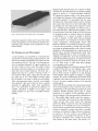
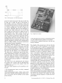
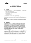
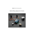
Microprocessors in Laboratory Automation
M. Bos
Technical University Twente, Department of Chemical Technology, Enschede, The Netherlands
A description is given of the construction and operation of microcomputer systems, the types and functions of their various components, their programming
and the peripherals and interfaces that are required
to use microcomputers in a laboratory environment.
The particulars of the use of microcomputers in laboratory automation are presented in some detail and
illustrated by an example concerning computerization
of the trace analysis of some metals.
Many of us still visualize a computer as bulky equipment occupying the better part of large rooms where
the atmosphere is kept at constant temperature and
humidity (Fig. 1). Nowadays, however, computers
can be as small as desktop calculators, thanks to
developments in the field of microelectronics (Fig. 2).
The large installations still serve their purpose in
number-crunching, data-base management, etc., but
the superminiaturization with the technique called
Large Scale Integration (LSI) that produces thousands of transistors and other electronic circuit elements on a few square millimeters of a silicon chip,
can bring computing power to virtually every spot
where it is needed. Accompanying the miniaturization
there has been a spectacular reduction in the cost
of computing power during the last decade. Together
these factors are responsible for new concepts in in-
Fig. 1. Technical University Twente, Central Computerfacility
14
strumentation and automation. A great number of
measuring instruments nowadays is "smart", that is
they not only provide the data of interest but also
analyze these data and act on the results of these
analyses.
The universal building block in these intelligent instruments is the so-called microprocessor, a complicated electronic circuit most often contained in one
package having the size of about 1.5 x 5 cm and from
24 to 40 connecting pins (Fig. 3). This device can
perform a multitude of complex tasks for which the
commands are stored in additional memory devices.
The multifunctionality and great flexibility offered
by this set-up enable a high degree of sophistication
together with relatively short development times. For
small series production of scientific instruments stan-
Fig. 2. Microcomputer with video terminal
Naturwissenschaften 68, 14-19 (1981)
9 Springer-Verlag 1981
Fig. 3. Microprocessor chip, 40-pin dual in-line package
dard microcomputer systems can be used, thus reducing the development costs of electronic circuitry. Programming takes the place of the construction of electronic circuits.
The Microprocessor and Microcomputer
A microcomputer is an assembly of a microprocessor
and devices to provide timing, program memory, random-access memory and interfaces for input and output operations (Fig. 4). The task of the microprocessor is to perform arithmetic or logical operations on
the data it takes in and to send the results of these
operations to printers, displays or to instrument interfaces that evoke control functions. The data has a
digital form, that is it consists of strings of bits. A
bit stands for binary digit, a digit that can only take
the values one or zero. The number of binary digits
that is treated as an entity is called the word length.
Early microprocessors had a four-bit word length,
but nowadays 8 bits and 16 bits are more common
especially in applications where some calculations
have to be performed. In general the efficiency of
complex operations is highest in the larger word
length machines as more bits are handled simultaneously.
X-TAL
F
ADDRESS BUS
PY;s%R
f
DATA BUS
MEMORY
i/o ~ ]
97
CONTROL BUS
Fig. 4. Microcomputer system block diagram
Naturwissenschaften 68, 14-19 (1981) 9 Springer-Verlag 1981
Supporting the microprocessor are a number of chips
of which one, the clock generator, provides the timing
signals by means of a crystal-controlled oscillator.
All operations somehow relate to the clock periods,
so the higher the frequency of this oscillator the faster
the system operates. It is noteworthy that for some
microprocessor types selected species can be obtained
that accept clock rates two to four times higher than
the standard one. The other devices needed to constitute a complete microcomputer are memory and input/output interfaces. Microcomputer memory comes
in various kinds. Read Only Memory (ROM) is meant
for program storage. Its content cannot be changed,
is nonvolatile, i.e., no power is needed to preserve
it, and it requires a rather high initial investment
for its production. So its primary use will be in highvolume productions. Programmable Read Only
Memory (PROM) is also meant for program storage.
It has the same properties as ROM; the only difference being its programmability with relatively simple
equipment. Once programmed its content cannot be
altered either. Erasable Programmable Read Only
Memory (EPROM) can be used to advantage in developing new applications. It can also be programmed
with relatively simple equipment, its content is nonvolatile but can be erased by exposure for about 15 min
to a UV light source, so with some effort changes
to the program can be made.
For storing changing data read/write memory (RAM)
is needed. Here there are two different types: static
and dynamic RAM. The static RAM will hold its
data as long as power is applied to it, but dynamic
RAM requires refresh signals in addition to supply
voltages. The power requirements of dynamic RAM
is generally lower than for static RAM but the circuits
to use it are more complex because of the required
refresh signals.
The I/O interfaces constitute the communication links
of the microcomputer system with the outer world.
A distinction can be made between parallel and serial
interfaces. Parallel interfaces allow input or output
operations of a number of bits (generally equal to
the word length of the microprocessor) simultaneously. This enables high transfer rates but requires a
lot of connecting wires between the microcomputer
system and the outer world. Slower but requiring
much less cabling is serial I/O. Here the information
bits are sent out or received one by one. As microprocessors operate on parallel data, parallel to serial conversion is required for output and serial to parallel
conversion is required for input. Moreover protocols
are needed so that the receivers can assemble the
incoming bits to meaningful bit patterns. It will be
clear that a transmitter and a receiver of serial data
must operate at the same speed. This speed is ex15
level
t
.startl,
I
I
J
I
i stops,
8 d a t a bits
I
I
i
I
mark(1)
space (0)
0
.
time
Fig. 5. ASCII character A for serial transmission
pressed in baud (bits/second). But there should also
be some way to detect the start of each group of
bits forming a word. In asynchronous systems the
line connecting the interface to the remote instrument
is normally at logical one level (mark) and the start
of a word is signalled by a start bit at logical zero
level (space). Thereafter follow the bits belonging to
the data word, finally followed by one or two stop
bits at logical one level (mark) to signal the end of
the transmitted word. Figure 5 shows this type of
serial transfer of data. The overhead of start and
stop bits is absent in synchronous serial data transfer.
Now special bit patterns (sync characters) are sent
during periods that the line is idle to obtain the synchronization between transmitter and receiver. Chips
specially designed for all these serial communication
tasks are called USART's (Universal Synchronous/
Asynchronous Receiver/Transmitter).
The various supporting chips are connected to the
microprocessor via so-called buses, sets of parallel
wires along which signals are transferred. The data
bus is a bi-directional path on which data is transferred from the microprocessor to memory and I/O
and from I/O and memory to the microprocessor.
The address bus is unidirectional and its state determines which memory location or I/O interface is to
be operated upon. The number of address-lines determines the maximum amount of memory locations
that can be addressed. A number of 16 address lines
is fairly common and can address 216=65536 different locations.
The control bus is also unidirectional and indicates
the current type of activity that the microprocessor
is engaged in, i.e., memory read, memory write, I/O
read, I/O write, etc.
The basic system operation can be described as follows [I]:
1) The microprocessor issues an activity command
on the control bus.
2) The microprocessor issues a binary code on the
address bus to identify which particular memory location or I/O device will be involved in the current
process activity.
16
Fig. 6. Single-board computer
3) The microprocessor receives or transmits data from
or to the selected memory location or I/O device.
4) The process is repeated from step 1 with the next
activity command.
The strength of this concept lies in the fact that this
scheme is used to fetch commands to be executed
by the microprocessor as well as to manipulate data.
The total number of different commands that a microprocessor can execute is called its instruction set. Each
instruction is coded as a particular sequence of O's
and l's, the length of which equals the word length
of the microprocessor. During operation the microprocessor fetches these instructions from memory, decodes them and takes the appropriate action.
The microcomputer configuration described so far
is the minimum required, i.e., for use as an intelligent
controller built into a measuring instrument. The microcomputers available in this form and for these
purposes are called single-board computers (Fig. 6).
For stand-alone applications packages with their own
power supply in one enclosure together with some
I/O interfacing to a video display and keyboard are
available as personal or homecomputers.
More sophisticated are the development systems.
Meant for developing microcomputer applications for
mass production these development systems incorporate all the tools needed for the design and testing
of programs and the simulation of small microcomputer systems.
Naturwissenschaften 68, 14-19 (1981) 9 Springer-Verlag 1981
Microcomputer Programming
As stated above a microcomputer program consists
of a set of instructions in binary machine code, i.e.,
sequences of zeros and ones. It is possible to write
programs in this binary machine code, but it will
be clear that this is very time-consuming and very
likely errors will be made. The idea of using the computer to aid in programming has been a very successful one. At the lowest level of programming support
are computer programs that convert mnemonics for
the machine instructions and operands to binary machine code. These assemblers currently still handle
the bulk of microcomputer programming. With the
use of this assembly language the programming of
mathematical functions still is a formidable task.
Much programming effort can be saved by the use
of higher-level languages like BASIC, FORTRAN,
COBOL and PASCAL. One statement in these languages corresponds to a great number of machine
instructions. To convert programs written in these
higher-level languages to binary machine code computer programs known as compilers are used. The
language PASCAL [2] is now gaining more and more
terrain for microcomputer applications. It has the
advantage that it allows a modular approach in the
construction of programs.
A newly written program seldomly is correct the very
first time. Typing errors and errors in the logic can
easily be corrected with the aid of so-called editor
programs.
It is not strictly necessary that program development
takes place on the same type as the target microcomputer. Programs are available running on larger systems like minicomputers and main frames that produce the binary code for various types of microcomputers. These cross-compilers and cross-assemblers
use the extensive facilities of the larger systems like
lineprinters, large libraries of standard routines, disk
storage, etc., and thus shorten the turnaround times
in development.
Peripherals
Microcomputers communicate with their environment with binary-coded signals. Most of the world
exterior to the microcomputers, however, is not oriented towards this type of communication. Therefore
peripherals have been developed that convert various
types of signals to binary information and vice versa.
The human user can exchange information with the
microcomputer via teleprinters, lineprinters, typewriter keyboards and videodisplays. Currently audio sigNaturwissenschaften 68, 14-19 (1981)
9 Springer-Verlag 1981
nals have also come into use in the form of spoken
English as output and voice terminals for input.
For instrument control usually some analog signals
are required. Digital to analog converters (DAC) can
produce these signals from binary computer output
signals. Steppermotors, however, can be controlled
directly by binary signals: one pulse applied causes
a specific angular movement. In most of the measurements of physical quantities transducers are employed
that present the result of the measurement as an electrical voltage. These voltage values have to be converted to binary code before they can be used in
a microprocessor: analog to digital converters (ADC)
perform this task. Important features of these devices
are speed and accuracy. Signals should be sampled
at a rate at least twice their highest frequency component.
As explained before microcomputers can address only
a limited amount of memory. Many applications require storage of large amounts of data, whereas in
development systems a great number of standard routines should be readily available. Mass-storage devices
like hard- and floppy disks handle these types of storage. Performance of these devices is determined by
access time and maximum storage capacity.
Microcomputer Applications in Laboratory Automation
Laboratories arc concerned with the acquisition and
interpretation of data. The data acquisition is carried
out with the aid of measuring equipment. Automation
of this equipment not only relieves the experimenter
from the tedious task of taking readings from instruments, but also improves the accuracy and enables
very high data rates and complicated measurement
protocols. If the measured data is used to adjust experimental parameters (closed-loop control) the measurements can be optimized to speed, accuracy, etc.
Apart from reducing the need for human effort and
presenting new possibilities in data acquisition computerization has also a lot to offer in the field of
data interpretation. Complex mathematical operations can be performed whereas presentation of the
data in various report formats and in graphical form
facilitates the use of the results.
A number of examples of microcomputer-controlled
commercial instruments for atomic absorption, infrared and ultraviolet/visible light spectrophotometry
and chromatography is given in [3]. The built-in microcomputers provide facilities that lighten the task
of the operator, i.e., recallable settings of all instrument parameters, auto-adjustment of various parameters, diagnosis of malfunctioning, etc. They also sup17
Ework
metal 1 - -
~ i~
- - metal 2
printer display
I
f
)a~7;e,
__
-<___
f
parallel,/o
SINGLE
BOARD
COMPUTER
i ~
--
__
DE
mallei
I/o
~'time
teletype
~
etay
Fig. 7. Potential/time curve for potential stripping analysis
port the evaluation of the data by baseline corrections,
linearization of calibration plots and peak integration.
The application of a single-board computer for the
technique potential stripping analysis given by Anf/ilt
and Strandberg [4] shows that it is possible to construct elaborate equipment with standard components.
To demonstrate the typical approach for the use of
a microcomputer in an analytical technique this example is presented in some detail.
Potentiometric stripping analysis is a technique used
in the trace analysis of metals. In this technique the
sample solution of the metal ions to be determined
is subjected to electrolysis. The working electrode is
made of glassy carbon, a chemically rather inert material that can be polished to a high degree of smoothness. Mercury ions are added to the sample solution
and thus mercury is deposited on the electrode together with the metals from the sample. This results
in a thin film of mercury on the electrode in which
the metals to be determined are amalgamated. 9
the electrolysis period the voltage source for this electrolysis is disconnected from the working electrode
and the reduced metals in the mercury film are reoxidized by an oxidant into the solution. This reoxidation process changes the potential of the electrode
versus a reference electrode. The resulting potential
versus time curve is given in Fig. 7, The end of the
reoxidation process for a given metal can be recognized by a break in this curve. The time for each
metal to be stripped from the electrode is proportional
to the initial concentration in the sample and electrolysis time. Figure 8 shows a schematic diagram of the
complete equipment. A D/A converter is used to control the cell voltage during electrolysis. A relay serves
to disconnect the D/A converter from the cell during
the reoxidation, whereas an A/D converter measures
the electrode potential during this phase of the experiment. The computer program not only controls the
experiment completely but also evaluates the results.
18
auxiliary workincl
electrode elec trcYJe
ref
electrode
sample cell
Fig. 8. Block diagram of equipment for potential stripping analysis
9It is noteworthy that the authors use the higher-level
programming language BASIC to ensure flexibility
in changing the analysis scheme. To access the peripheral hardware special functions written in machine
language were added to the standard BASIC. This
technique combines the ease of programming in
higher-level languages with the power of control over
the hardware that machine language programming
permits.
Trends in the Use of Microcomputers
for Laboratory Automation
Over the years the prices of microprocessors and
memory have gone down considerably and they still
continue to do so. This will make computer power
available in rather simple instruments. The same tendency can be observed for mass-storage devices. Magnetic bubble memories [5] are now being introduced
in this field. Compared to the electromechanical devices they are more reliable and require less maintenance.
The microprocessors become more powerful, the new
generation having a 16-bit word length, improved
speed and elaborate instruction sets. Machine instructions for division and multiplication as well as for
string handling are standard features now. More complex data processing like fast Fourier transform [6]
and multiparameter curve-fitting [7] can become builtin functions of laboratory equipment with this type
of microprocessors.
With the acceptance of the IEEE-488 laboratory bus
standard more and more manufacturers equip their
instruments with interfaces for it and the required
Naturwissenschaften 68, 14-19 (1981) 9 Springer-Verlag 1981
software now is available for most types of microprocessors.
In contrast to research laboratories diagnostic laboratories, e.g., laboratories for process control and for
clinical chemistry, have a workload of routine measurements accompanied by a heavy demand on reporting. Developments in this area include computer
networks. The microcomputers dedicated to measuring instruments are coupled via minicomputers to
mainframes. Experiments are completely controlled
by the various microcomputers but the results are
coordinated by minicomputers. Large data bases can
be accessed via the links to the mainframe computers.
These developments shift the main cost of laboratory
automation from the hardware to the software. Effi-
Naturwissenschaften 68, 14-19 (1981)
9 Springer-Verlag 1981
ciency of the programming effort thus is of major
importance. Here computer networks can also help
as the vast resources of mainframe computers can
be made available to the lowest level [8].
1. Intel 8080 Microcomputer Systems User's Manual, p, 3-1. Intel
Corporation 1976
2. Jensen, K., Wirth, N. : Pascal User Manual and Report. BerlinHeidelberg-New York: Springer 1975
3. Franke, G. : Chemie~Technik 7, 83 (1978)
4. Anf~ilt, T., Strandberg, M. : Anal. Chim. Acta 103, 379 (I978)
5. Hodges, D.A.: Sci. Am. 237, 130 (1977)
6. Cooley, J.W., Tukey, J.W. : Math. Comp, 19, 297 (1965)
7. Wentworth, W.E. : J, Chem. Educ. 42, 96 (1965)
8. Dessy, R.E. : Anal. Claim. Acta 103, 459 (1978)
Received July 7, 1980
19