1
NUMBER 905
INDICATING/RECORDING (ATA 31)
PLANEVIEW® MASTER OPERATING SYSTEM
SOFTWARE UPDATE
July 26, 2006
Gulfstream G450
Aircraft Service Change 905
“July 26, 2006"
PILOTS INFORMATION SHEET
PLANEVIEW MASTER OPERATING SYSTEM SOFTWARE UPDATE
This service change installs the PlaneView Master Operating System (MOS) software
EB7031236-00407 on G450 aircraft.
Airplane Flight Manual (AFM) Revision 11, or later-approved version, will be required as a
result of this service change.
PLEASE DETACH AND GIVE TO FLIGHT DEPARTMENT PERSONNEL
Aircraft Service Change prepared by Gulfstream Aerospace, Savannah International Airport, PO Box 2206, Savannah
Georgia, 31402-2206, USA. © 2006, Gulfstream Aerospace. All rights reserved, including the right to reproduce this
publication. No part may be reproduced, stored in any retrieval system or transmitted in any part or form or by any
means electronic, photocopying, microfilm, microfiche, mechanical or otherwise, without prior written permission of
Gulfstream Aerospace.
This technical data is controlled under the Export Administration Regulations by General License TSU. It may not be
transferred to a third party without the prior written approval of the U.S. Department of Commerce.
Gulfstream G450
Aircraft Service Change 905
“July 26, 2006"
PILOTS INFORMATION SHEET
PLANEVIEW MASTER OPERATING SYSTEM SOFTWARE UPDATE
This service change installs the PlaneView Master Operating System (MOS) software
EB7031236-00407 on G450 aircraft.
Airplane Flight Manual (AFM) Revision 11, or later-approved version, will be required as a
result of this service change.
PLEASE RETAIN THIS COPY WITH THE ASC BOOKLET
Aircraft Service Change prepared by Gulfstream Aerospace, Savannah International Airport, PO Box 2206, Savannah
Georgia, 31402-2206, USA. © 2006, Gulfstream Aerospace. All rights reserved, including the right to reproduce this
publication. No part may be reproduced, stored in any retrieval system or transmitted in any part or form or by any
means electronic, photocopying, microfilm, microfiche, mechanical or otherwise, without prior written permission of
Gulfstream Aerospace.
This technical data is controlled under the Export Administration Regulations by General License TSU. It may not be
transferred to a third party without the prior written approval of the U.S. Department of Commerce.
Gulfstream G450
Aircraft Service Change 905
“July 26, 2006"
The design change effected by this document is FAA approved. If a compliance time,
inspection interval or process requires FAA approval; such approval will be noted by the
affected words appearing with an asterisk or note designating FAA approval.
The design of this Aircraft Service Change (ASC) is approved by aircraft type design data for
installation on aircraft registered for operation in accordance with applicable regulations of
the United States Federal Aviation Administration. Individual approval should be obtained
from the appropriate airworthiness agency prior to installation on aircraft registered outside
the United States.
The design of an ASC is configured to a standard (“greenie") production aircraft. If spare
wires, pin connections or locations called out have been used for another modification, the
installing agency must ensure the development, documentation and approval of any required
deviations.
The following instructions, in step-by-step form, are written as a guide to perform this ASC.
Compliance with safe maintenance practices as recommended in the Aircraft Maintenance
Manual and FAA regulations is required.
Gulfstream considers this ASC a means to enhance aircraft capabilities to meet individual
operator requirements. The modification is not related to any safety or airworthiness
condition.
Subject:
Indicating / Recording Systems (ATA 31) - PlaneView
Master Operating System Software Update
Purpose/Discussion:
This service change installs the PlaneView Master
Operating System software EB7031236-00407 on G450
aircraft.
This service change enhances the overall performance
and reliability of the PlaneView Avionics System.
Description/Man-Hours Required
Per Aircraft:
This service change installs updated Master Operating
System software, P/N EB7031236-00407. This ASC
must be installed in conjunction with G450 ASC 014A.
Approximately 10 man-hours will be required for this
installation.
Appendix A of this ASC provides detailed PlaneView
software information including; known anomalies and
planned resolutions, operational information issues,
and issues under investigation.
Approved Engineering Data:
The source data for this aircraft service change is:
1159ASC47905 Rev "-", Top Drawing – Certification
Charlie II (MOS)
Page 1 of 6
Gulfstream G450
Aircraft Service Change 905
“July 26, 2006"
Prerequisites:
G450 ASC 903 or ASC 904 - PlaneView Master
Operating System Software Update
Concurrent Requirements:
G450 ASC 014A - PlaneView Avionics Enhancementmust be installed in conjunction with this service
change.
Associated Documents:
G450 Aircraft Maintenance Manual (AMM), Chapters
20, 31 and 34
Flight Manual
Revision/Supplement Required:
Airplane Flight Manual (AFM) Revision 11, or laterapproved version, will be required as a result of this
service change.
Publications Data:
Data concerning this service change will be published in
a future revision of the affected manual(s). This booklet
will provide technical data until the revision(s) are
published.
Effectivity:
This service change is applicable to Gulfstream G450
aircraft, serial numbers 4001-4057.
This or a similar change will be installed during Initial
Phase on Gulfstream G450 aircraft, serial number
4058 and subsequent.
Effect on Spares:
None
Special Equipment/Tools
Required:
Aircraft’s PC Laptop with Remote Terminal Tool version
16.3.2 or later. Refer to Gulfstream PlaneView
Maintenance Applications disk version 4.1 or later, PN
1159LAP59000
Skill Type Required:
Knowledge of the Gulfstream G450 PlaneView avionics
system will be required for this installation.
Price:
Prices are subject to change without notice.
Installed Price:
*See notes
Page 2 of 6
Gulfstream G450
Aircraft Service Change 905
“July 26, 2006"
*NOTE:
This ASC will be installed at no charge for a period of 24 months from the
release date noted on the cover of the aircraft service change if installed at
Gulfstream Aerospace or a Gulfstream G450 Authorized Warranty Repair
Facility. All other installations are subject to the prevailing labor rate of the
installing agency.
*NOTE:
This ASC Kit will be provided at no charge for a period of 24 months from
the release date noted on the cover of this Aircraft Service Change. After
the 24-month period has expired, this ASC Kit/s will be priced and sold.
*NOTE:
Coverage is granted per the terms and conditions of the Gulfstream Aircraft
Sales Agreement to the original purchaser or subsequent owner with
appropriate Assignment of Warranties on file with Gulfstream.
MODIFICATION INSTRUCTIONS:
A.
Prepare aircraft for safe maintenance. Refer to G450 AMM, Chapter 20-20-10.
B.
Ensure Steps A through E of ASC 014A, PlaneView Avionics Enhancement, have been
complied with.
C.
Apply electrical power to aircraft. Refer to G450 AMM, Chapter 20-20-10.
NOTE:
D.
Correct setup of the aircraft laptop with the CMC Remote Terminal Tool is
critical to the successful loading and operation of all software. Follow Data
Load Guide procedures CAREFULLY. Ensure any firewalls, anti-virus
programs or wireless LAN connections are disabled and the laptop is
connected to 60 Hz aircraft power.
Load the following software in accordance with GIVX-GER-9934, Section 2.0,
PlaneView Software Loading.
1.
*NOTE:
PlaneView Master Operating System software, Component of Top-Level System,
P/N EB7031236-00407.
Testing of this installation and the installations found in G450 ASC 14A
should be conducted only after all of the hardware and software installations
are completed. GIVX-SGER-905 is the only required test.
E.
Comply with G450 ASC 014A Steps F 1 through 10.
F.
Verify all software loads in accordance with GIVX-SGER-9934, Rev. “F” or later,
Section 6.0. ASC. Enter 16 digit INDS serial number recorded in ASC 014A Step A.2.
to access charts information as required.
Page 3 of 6
Gulfstream G450
Aircraft Service Change 905
“July 26, 2006"
The following changes were incorporated into the base Certification Charlie
II LDI for the Central Maintenance Computer (CMC):
NOTE:
•
AGM reset test is removed.
•
AGM Member system status is removed.
•
Nuisance AOA maintenance faults reported to the CMC and a blue
‘Check CMC’ CAS message being displayed has been prevented when
the AOA heaters are selected off.
G.
Perform Return-to-Service (RTS) Checkout Procedure GIVX-SGER-905 provided with
this service change.
H.
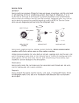
Verify Top-Level System software part number on Configuration Management Software
(CMS) screen matches the part number on the CD-ROM. Refer to Figure 1.
I.
Remove disk from laptop and store in aircraft.
J.
Discard previously used version of the PlaneView Master Operating Software CDROM.
K.
Remove electrical power from aircraft. Refer to G450 AMM, Chapter 20-20-10.
L.
Ensure work area is clean and clear of foreign objects (FOD).
M.
Document the following information on the attached service reply card and in the
aircraft logbook. Refer to Figure 1.
•
Top-Level System Part Number
•
Media Part Number
•
Media Serial Number
N.
Document the necessary information on the PlaneView Configuration Record located
within the MISCELLANEOUS section of the aircraft’s permanent maintenance records.
O.
Record compliance with this aircraft service change in the aircraft’s permanent
maintenance records and return aircraft to flight status.
P.
Report compliance with this aircraft service change to Gulfstream CMP via electronic
transmittal or fill out and fax the attached Service Reply Card.
Page 4 of 6
Gulfstream G450
Aircraft Service Change 905
“July 26, 2006"
WEIGHT AND BALANCE DATA:
The weight and balance of the aircraft is not affected
by this service change.
ELECTRICAL LOAD ANALYSIS DATA:
The effect of this change on the aircraft’s electrical
loading will be “0”.
PARTS REQUIRED PER AIRCRAFT:
Item
Part Number
1.
EB7031236-00407
2.
GIVX-SGER-905
*NOTE:
Nomenclature
Master Operating
Software
Return to Service
Checkout Procedure
Qty.
Notes/Alt./Substitutes
1
*
1
*
All drawings, publications and media software will be issued to the latest
revision.
Page 5 of 6
Gulfstream G450
Aircraft Service Change 905
“July 26, 2006"
Top Level
System Part
Number
Media Part
Number
Media Serial
Number
Figure 1
Page 6 of 6
Gulfstream G450
Aircraft Service Change 905
“July 26, 2006"
SERVICE REPLY CARD
PLEASE FAX THIS PAGE TO GULFSTREAM AEROSPACE CMP
FAX # 912-965-3598.
THE FOLLOWING AIRCRAFT SERVICE CHANGE HAS BEEN COMPLIED WITH:
ASC NUMBER
979050
A/C
AIRCRAFT TYPE
G450
COMPLIANCE DATE
AIRCRAFT HOURS:
AIRCRAFT LANDINGS:
PREVIOUSLY
COMPLIED WITH (PCW):
DATE:
NOT APPLICABLE:
DATE:
MEDIA TITLE
MOS
DISC INFORMATION
TOP LEVEL
MEDIA PART
SYSTEM PART
NUMBER
NUMBER
MEDIA
SERIAL
NUMBER
CMP CODE
TLS / MM
OFF:
319010 / 319012
ON:
319010 / 319012
SIGNATURE
TITLE / CERTIFICATE
NUMBER
COMPANY
COMMENTS / SUGGESTIONS / ACTIONS TAKEN:
Aircraft Service Change prepared by Gulfstream Aerospace, Savannah International Airport, PO Box 2206, Savannah
Georgia, 31402-2206, USA. © 2006, Gulfstream Aerospace. All rights reserved, including the right to reproduce this
publication. No part may be reproduced, stored in any retrieval system or transmitted in any part or form or by any
means electronic, photocopying, microfilm, microfiche, mechanical or otherwise, without prior written permission of
Gulfstream Aerospace.
This technical data is controlled under the Export Administration Regulations by General License TSU. It may not be
transferred to a third party without the prior written approval of the U.S. Department of Commerce.
Appendix A
APPENDIX A
PLANEVIEW SOFTWARE INFORMATION UPDATE
(updated July 14, 2006)
Open Issues and Planned Resolutions
NOTE:
THIS INFORMATION IS ADVISORY ONLY. This appendix contains neither
approved flight procedures nor official guidance. Consult the latest guidance
in the airplane flight manual (AFM) or quick reference handbook (QRH) for
flight procedures. Updates to this appendix can be found in the Waypoints
section of myGulfstream.com at the following link:
(https://www.mygulfstream.com/portal/customer/pilots/).
Anomaly
During Radar Altimeter Test, the Flight
Controls System page weight-on-wheels
indication will amber cross hatch and the ECS
load valve will close. Corrects with release of
Rad Alt test button.
Occasionally pilot and copilot display sensors
power up defaulted to ADS 3 and RAD ALT 1.
Condition may be associated with a low
voltage APU start. To resolve the issue, select
desired sensor.
NAV 1 and/or NAV 2 may power up with DME
Hold selected on. Must select DME Hold off
from the MCDU Nav Radio detail page.
If a step climb is entered in the flight plan and
the flight continues past the Bottom of Step
Climb point, the Vertical Track Change
message will be displayed each time the FMS
re-calculates performance data. Frequency of
the message display increases during large
turns. To clear message delete step climb
segment from performance init.
VNAV path deviation may not match between
pilot and copilot with possible automatic
disengagement of VNAV. Vertical direct-to will
re-sync the VNAV path deviation.
Infrequent auto throttle power lever changes
for speed control with an active speed target.
Disconnect auto throttle and re-engage to
stabilize power lever movement.
Selection of the DLK key may not always
result in display of the Datalink menu page.
Standby and Misc pages are typically
observed. Re-select DLK key. May require as
many as 3 attempts.
Resolution
Resolved in Cert Delta.
To be resolved in Cert Delta.
For consideration in Cert Delta.
For consideration in post Delta cert.
Investigation under way to determine cause of
problem – will correct in Cert Delta if cause is
determined.
To be resolved in Cert Delta.
To be resolved in Cert Delta.
Page 1 of 5
Appendix A
Anomaly
Uplink weather display does not update the
SEND button status in a timely manner if both
pilots have been accessing the uplink weather
selection tab. To clear, exit the Uplink WX
dialog and re-attempt several minutes later.
Failure rate of the weather requests was 4050%. From the method of data transmission
from the ground and improper construction of
the multiple segments which result in marking
the data failed. Verify request construction
and re-attempt selection with fewer segments.
Performance calculations may incorrectly use
the approach speed for descent predictions.
This can occur if the TO waypoint is in the
approach procedure or if the TO waypoint is
within the approach distance (15nm) defined
in the PERF INIT DEP/APP page. This error is
the result of direct clearance to the approach
waypoint from 1000+ miles. Avoid direct-to
selections of waypoints from distances of
greater than 1000 nm.
Single Engine Performance Predictions show
speeds that are 100 knots faster than the
single engine cruise speeds.
Autothrottle speed command receives
erroneous signal as flaps transit through 2°,
12° and 22° up or down when the autothrottles
are engaged in speed select mode. The speed
target change may not show on the Flight
Guidance Panel. The erroneous command will
gradually erode at a rate of 1 knot per second
to the correct speed target. Disengage
autothrottles to avoid speed change.
Datalink sends inaccurate position reports at
higher latitudes (60°N) or higher where the
tolerance limits of 3 minutes of longitude
equates to 1.5 NM or less. Datalink reports
passing the position earlier than actual point
passage.
Flex EPR cannot be selected for takeoff unless
a NAV source is selected in the FMS (NOTE:
this applies to G450/G350 aircraft only)
FMS predictions of time enroute and fuel
consumed for the last flight plan leg prior to
top of descent (TOD) are inaccurate. The
groundspeed and fuel flows for this leg will be
lower than actual, thus the FMS predicted time
enroute will be longer than actual and actual
fuel used will be more than the figure shown
on the FMS page. The degree of inaccuracy is
dependent on the length of the leg that
precedes TOD.
Resolution
To be resolved in Cert Delta.
To be resolved in Cert Delta.
To be resolved in Cert Delta.
To be resolved in Cert Delta.
To be resolved in Cert Delta.
Will be addressed in Cert Delta.
Will be addressed in Cert Delta.
Entering a pilot defined waypoint or route
waypoint just prior to TOD will minimize time
and fuel inaccuracies.
Fixed in Cert “D”.
Page 2 of 5
Appendix A
Operational Information Issues:
If operating on emergency batteries (E-batts), you don’t have to select EMER on ACPs to
talk on Radio 1. Selecting EMER on ACPs only bypasses PlaneView avionics interfaces and
connects the ACPs directly to Comm 1. Selecting E-batts or extending the EMER switch depowers a relay which ties ACP 1 and 2 transmit directly to Comm 1.
The Electronic Charts are loaded using the Honeywell blue disk in the DMU. The E chart
program resides on the AGMs and the individual approach charts are on the PCMCIA card
in the DMU. You can do a full load and load both or you can target load just the PCMCIA
card. If the AGM programs are out of date, it will show which AGMs are out of date in amber
on the Database page of the CMC. If the airport data or AGM programs are out of date,
when the Electronic Charts are opened, there will be an amber note saying the data may be
out of date. If everything is current, then the letters on the Elec Chart open page will be
white. Select the X in the top right corner of the Elec Chart page to go to the actual program.
If you experience power-up issues and do not want to dispatch with these issues, the
recommended course of action is to recycle the last power source that was applied, i.e. if
problems arise on application of battery power, turn battery power off for 30 seconds and
then re-apply. If problems arise after application of external power or APU power, then you
may be able to regain normal application by cycling those switches only. If this doesn’t fix
the issue, then removal of all power and waiting 30 seconds followed by a normal start is
the best procedure.
The datalink interface is now provided by Global Data Center. If you’re one of their
customers you can request the EPIC/PlaneView user’s manual which has a good
description of the operation of the new interface.
The logic on the EVS cooling valve message has been revised to only annunciate when the
cooling valve is not in the correct position. You’ll no longer get the message below 18,000’.
You must push the engine start switch for one second or more. A momentary button press
on start switch may not command the start valve to open (SVO icon not displayed) and you
may get a SVO Maint Required amber message (like the GV). If so, you’ll need to shutdown
and restart to clear the message.
The small “inverse airplane” icon on approach and airport electronic charts indicates that
the chart is drawn to scale and the spotter should be shown. With SIDS / STARS, and some
airports are not to scale and a spotter will not be shown.
Waypoint list altitudes are predicted altitudes only. Check the FMS for the constraints.
Also, you can only get WP list on DU 1 or 4 after selection of an engine page, then WP list.
This is per design.
All four APMs have to be up and valid to do an EVS raster alignment. APM 1 is in NIC 1
which is on MAU 1A; APM 2 is on NIC 4 which is on MAU 2B; APM 3 is on MRC 1; APM 4 is
on MRC 2.
In normal operations, there’s a Master/Slave audio warning system. Thus you can hear
items like the AP and AT disconnect at the same time as Ground Proximity altitude callouts.
If MW 1 or 2 fails, audible warnings are annunciated sequentially and each audible warning
has to annunciate completely before the next warning can sound. Thus, if you disconnect
autopilot during landing at say 45’, you will hear the autopilot disconnect tones but the 40’
and 20’ EGPWS callouts may be delayed such that they appear to be inaccurate (e.g. the 40’
call at 20’).
Page 3 of 5
Appendix A
Operational Information Issues Continued:
If operating on battery power only, the Horizontal Stabilizer will show failed on the Flight
Controls page. Once the HMG master is on and up to speed (HMG fault light out) the
stabilizer will work normally. Normal operation can be confirmed by going to emergency
stabilizer and using trim switch.
An amber flashing WX will be shown up on the HSI and INAV displays if the radar is
transmitting but is not selected for display on either display. Also, at ranges less than 5 half
range, WX will not be available and the WX annunciation will flash amber.
It is normal for the aileron indication to fill completely at approximately 2/3 of full travel on
the Flight Controls display.
If the FMSs experience a power interruption, temporary NOTAM information will be lost.
If an MRC fails, the other MRC will take over the Comm, Nav and HF tuning and display
functions. The radio page on the MCDU will remain fully functional except for the loss of the
ADF and Transponder in the failed MRC.
A “stuck” microphone logic is incorporated in the ACPs. After a 30 second mic use period,
the transmitter will disengage. This feature also applies to SATCOM - you must release the
mic button every 30 seconds in order to keep the transmitter online. This operational logic
is per design; however a new CAS message and MCDU message annunciating the condition
is scheduled for Cert Delta.
Whenever the Checklist Function is selected using the button on the Display Controller, the
checklist will appear in the lower 1/6 window of Display Unit #3 as the default location of
this function. The checklist may be positioned to any other location using the appropriate
selection on the Display Controller or CCD.
If selecting menu options on the I-NAV display results in only a short menu containing only
“show info” and “center map” then this indicates that there is a disagreement between the
AGM nav database and the FMS nav database. This most likely will occur when the FMS
database is updated on the regular cycle, but the AGM database update is omitted.
In Cert “C-ll” the automatic Advanced Graphics Module (AGM) reversion feature has been
disabled while in flight. If an AGM or Display Unit (DU) fails while in flight, it may not be
recovered. The Display Unit Control switches that were used to select an alternate AGM for
a Display Unit have no effect in the ALT position while airborne.
However, the inflight display format conversion will automatically switch according to the
established default settings to ensure the preservation of a PFD display for each pilot and
the display of CAS messages and Engine Data. If the display format has switched due to a
DU or AGM failure, that display format is “latched”. If the failed AGM or DU subsequently
recovers and is found to be usable, the “latched” display format may be released from the
“latched” condition by depressing the 2/3 display button on the display controller for three
(3) seconds. A different display format may then be selected.
If the aircraft is on the ground and a DU or AGM is found to be inoperative, the manual DU
Control Switches may be positioned to ALT (on the ground only) in order to configure the
operational DUs and AGMs in accordance with the MMEL for dispatch – however, one DU (#
3) will then be inoperative. The following matrix shows the effect of the ALT position
selection:
Page 4 of 5
Appendix A
Operational Information Issues Continued:
AGM condition / switch
position
All AGMs operable / NORM
AGM 1 FAIL / DU 1 ALT
AGM 2 FAIL / DU 2 ALT
AGM 3 FAIL / DU 3 ALT
AGM 4 FAIL / DU 4 ALT
DU 1
DU 2
DU 3
DU 4
AGM
1
AGM
2
AGM
1
AGM
1
AGM
1
AGM
2
AGM
4
AGM
4
AGM
2
AGM
2
AGM
3
AGM
4
AGM
3
AGM
3
AGM
4
AGM
3
X
X
X
X
The automatic engagement of autothrottles by the Envelope Protection System is inhibited
in Cert “C-ll”. The autothrottles will not engage if the aircraft speed approaches Vmax or Vmin.
All known software conditions that caused DU blanking issues have been resolved in Cert
“C-ll”; however, the AFM and QRH procedures have been updated to provide guidance in
dealing with DU blanking caused by faulty Network Interface Controllers (NICs) and/or
Advanced Graphic Modules (AGMs).
Issues under Investigation:
If the Preview mode is used to tune an onside ILS on the Progress page and then
subsequently switching to the offside Nav or FMS sources and cycling through the offside
Nav or FMS sources using the DC, the onside Nav previously tuned to the ILS in Preview
will revert back to autotune.
Occasionally on power-up or after a power interruption, FMS #1 will not accept any input.
When using the “what if” initialization mode on the MCDU to review the flight plan at a
different Mach speed but not selecting the new speed for use and subsequently making a
change to the flight plan (e.g. deleting a waypoint), the “what if” Mach speed is
automatically selected and placed in the current performance initialization data on the
MCDU.
Datalink automatic position reporting may fail after 1½ to 2 hours of flight or if VHF Datalink
is lost.
Weather Radar status is shown in red on CMC WX Summary page; however, radar functions
normally. This is thought to be a CMC interface communication problem.
If the existing flight plan is replaced by an identical flight plan via datalink, all three FMSs
may reset.
Uplink wind information is displayed with a green area shown that does not correspond to
any of the wind velocity color cues on the wind speed reference legend.
Unless the throttles are at idle, Flex EPR takeoff cannot be selected.
Entering a Flight Plan with over 100 waypoints will result in a corrupted Custom Database.
When the flight plan with 100+ waypoints is closed on the FMS, the other two FMSs will go
to a cold start and the FMS used to enter the Flight Plan will go to single mode with a
corrupted Custom Database. To view a presentation on how to restore the FMSs to normal
operation click here.
Page 5 of 5