1
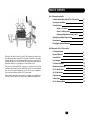
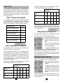
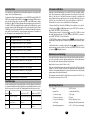
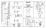
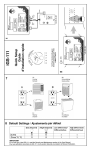
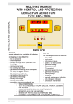
TABLE OF CONTENTS
Part-1 Setting up the controller
Contents and description of the iGS-100 CO2 controller
Tips on proper installation
Controller Outputs
Output 1 : CO 2 control
Output 2 : Auxiliary control
Setting operating modes for output 1 and 2
Adjusting Day and Night Setpoint values
Display functions
Displaying the Dynamic Differential
3
4
5
5
5
5
6
7
7
Part-2 More on the iGS-100 CO2 controller
CO2 control sequence
Welcome to the world of smart CO2 control. We are pleased you have chosen
the intelligent Growing Systems iGS-100 product to benefit from the added
yield and quality CO2 controlled environments can give you ! Apart from its
reliability and precision, you will benefit from incorporated smart features
that will work with you to optimize your CO2 and climate control.
The first part of this manual aims at giving you a quick start and a global
overview of all basic functions and configuration options. The second part will
give you a more detailed explanation on the control loops, configuration
options and smart features that the iGS-100 works with.
We are always interested in any comments or suggestions you might have.
Feel free to let us know at the following e-mail : [email protected] .
8
8
9
9
10
10
10
11
11
11
12
Dynamic Differential
Controller Hints
Error Messages
CO2 Sensor calibration
Maintenance and warnings
iGS-100 Specifications
iGS-50 Specifications
Product warranty
Product repairs
iGS-100 Operating Modes
2
PART-1 SETTING UP THE CONTROLLER
Contents and description of the iGS-100 CO2 controller
The iGS-100 CO2 smart controller is composed of the following items :
The iGS-100 control
Four Digit
numeric display
Day and night setpoint
keys : Hold down one of
these keys and use the
up and down button to
adjust to desired CO2
levels
Day/Night photosensor
Dust filter and air input
Internal fan
air output
Output box
connector
The iGS-50 control
Up and Down keys : use
these keys to scroll available values or operating
modes
Output #1 : CO2 control. Both outputs will
turn on automatically
according to operating
mode -xx.
Output #2 : Auxiliary
control. Both outputs
will turn on automatically according to operating mode -xx.
6 feet 125Vac 15A
power cord
6 feet cable to connect with
the iGS-100 CO2 Controller
Tips on proper installation
The iGS-100 CO2 control box should be placed as close as possible to the
plant canopy where light can be sensed by the photosensor and CO2 sampled
taking care not to expose the controller too close to the CO2 source, air evacuation points or heating/cooling equipment. The control box is equipped with
an internal fan that speeds up sampling the air. Do not to expose these vent
holes to potential sources of moisture or dirt. A lint filter is held by Velcro
pieces under the controller. The filter should never be removed indefinitely.
Take care in not exposing the sensor to insufficient light during the day and
light during the desired night cycle.
When fixing the control box take care in not over-tightening the screws in the
flap holes. The enclosure is made out of solid ABS plastic but a strong compression impact with a big screw can crack the enclosure. Make sure that the
wall upon which the control and
output boxes will be fixed is flat.
Take care in not bending the enclosures.
Usually the CO2 source is located
in the middle or over the garden
whereas the controller will be fixed
right outside of your garden limits.
The iGS-50 control Box can be fixed
anywhere around the control box without kinking or binding the 6 feet connection cable.
Once both enclosures are properly
installed, plug the 120 Volts power
cords into a 15 A 120 Volts electrical outlet. Then connect the cable
supplied with the controller into
the RJ-45 jack situated under each
enclosure. The controller will turnon and warm-up.
Disconnecting the cable from
either side will interrupt the controller’s operation. Once reconnected the controller will reboot
and warm-up the CO2 sensor (32
seconds). All operating modes and
values entered before the interruption will be retrieved automatically from memory.
Now that we have done the “Plugging”, let’s get into the “Growing”.
The product is completed by this user’s manual and a complimentary intelligent Growing Systems user sticker.
3
4
If you wish for the auxiliary output to be OFF except when the CO2 output is
ON, the following table will give you your operating mode.
Controller outputs
Once the controller is properly installed it is important to configure the controller’s
two (2) independent outputs according to the grower’s objectives. Through the following operating modes output 1 (CO2 control) can perform CO2 enrichment
and venting only during the day, the night or day and night. Output 2
(Auxiliary control) benefits from the same choice as for output 1 and offers
timer associated functions.
Output 1 : CO2 output control configuration
The output labeled as number “1” performs the functions associated with the
CO2 control. Usually if output 1 is configured to reduce CO2 in the air you will
plug an extraction fan into it. On the other hand if output 1 is configured to
add CO2 in the air you will plug a CO2 generator of some sort in output 1.
The CO2 control loop will:
Code
Add (enrich) CO2 during the day only
1-01*
Add (enrich) CO2 during the night only
1-02
Add (enrich) CO2 day and night
1-03
Reduce (vent) CO2 during the day only
1-04
Reduce (vent) CO2 during the night only
1-05
Reduce (vent) CO2 Day and night
1-06
5 min.
10 min. 15 min. 20 min.
Day
2-31
2-32
2-33
2-34
2-35
Night
2-41
2-42
2-43
2-44
2-45
Day and night
2-51
2-52
2-53
2-54
2-55
Setting operating modes for output 1 and 2
The output labeled as number “2” performs control over the auxiliary equipment that can be used when controlling CO2 levels.
The auxiliary output can be configured to be ON or OFF during the day, the
night or day and night (row choices in the table). In any of the latter choices,
the auxiliary output will toggle state when the CO2 output turns ON. The auxiliary output returns to normal when the CO2 output turns OFF except if you
choose an additional delay (5, 10, 15 or 20 minutes, column choices in table)
at the end of which the auxiliary output will return to normal (except if another injection cycle is in progress).
If you wish for the auxiliary output to be ON except when the CO2 output is
ON, the following table will give you your operating mode.
Additional delay to keep auxiliary output OFF during CO2 sequence
Auxiliary output is ON
during the :
0 min.
5 min.
Day
2-01*
2-02
2-03
2-04
2-05
Night
2-11
2-12
2-13
2-14
2-15
Day and night
2-21
2-22
2-23
2-24
2-25
5
0 min.
Operating mode 2-____
Output 2 : Auxiliary output control configuration
* Factory default
Auxiliary output is OFF
during the :
Note : If the auxiliary output is configured to be OFF during the day except when CO2
output is ON, the auxiliary output will always be ON during the night. Auxiliary output
OFF during the night except when CO2 output is ON will also force the auxiliary output
to be ON during the daytime.
Operating mode 1-____
* Factory default
Additional delay to keep auxiliary output ON during CO2 sequence
10 min. 15 min. 20 min.
Once you have chosen the operating mode associated with the role you want
each output to perform you have to enter it into the controller.
1- Press and hold the SETPOINT and NIGHT
SETPOINT button simultaneously. The display
will show the operating mode value -xx, -xx
or -xx.
2- Let go of both keys and repress them
simultaneously to toggle between operating
mode value ( -xx, -xx or -xx) .
3- To change the value of the displayed operating mode simply use the UP and DOWN buttons until the desired code is
displayed while maintaining pressure on the both SETPOINT keys.
Once the SETPOINT and NIGHT SETPOINT buttons are released the display
returns to showing the actual CO2 reading and the controller will perform the
configured behavior within 4 seconds.
Adjusting day and night setpoint values
Now you can set your target CO2 levels for the daytime and nightime.
1- Press and hold the SETPOINT button and
the display will show you the actual day setpoint value.
2- To change that value simply use the UP
and DOWN buttons while maintaining hold
on SETPOINT button. Holding the UP or
DOWN button for more than 4 seconds will
increase the speed at which the value will be
modified.
3- Release the SETPOINT button to return to showing the actual CO2 concentration. The controller will respond to the new value instantly and according
to its output configuration.
6
Setpoints adjustments for CO2 control are adjusted through 50 ppm
increments. Going over 4900 ppm will rollover the display to 0 ppm.
1- Holding down the NIGHT SETPOINT and
using the UP and DOWN keys will adjust the
night setpoint.
When you chose the controller to control CO2 levels day and night the
controller will use the setpoint value during the day and the NIGHT
SETPOINT value during the night even when in day and night modes.
PART-2 MORE ON THE iGS-100
CO2 Control sequence
When the controller is configured to add CO2 in your grow room, it will activate both slots of output 1 (CO2 control) when the sensor detects levels under
the user defined levels minus the Dynamic Differential. The Dynamic
Differential is subtracted to the setpoint to determine at what level the enrichment process has to stop to attain the actual valid setpoint without over or
undershooting (CO2 gas moves slowly in your grow room).
When on the other hand the controller is configured to vent CO2 out of your
grow room, it will activate both slots of output 1 (CO2 control) when the sensor detects levels over the user defined setpoint plus the Dynamic
Differential. The Dynamic Differential is added to the actual valid setpoint to
determine when to stop the venting process without under or overshooting.
Dynamic Differential
Display functions
The controller will flash the CO2 levels displayed when CO2 venting or enrichment is taking place.
When the dot situated at the bottom right of the rightmost digit is visible,
another value than the actual CO2 reading is being displayed.
When the Hint function is activated (see page 9) the same dot (rightmost
digit) will flash when hint codes are available.
Displaying the Dynamic Differential
The Dynamic Differential is the window of operation that the controller will
have chosen to optimize setpoint fidelity without provoking annoying repetitive switching or setpoint over and undershoots. The value takes approximately a full day of normal operation of your grow room to stabilize. The
smaller your Dynamic Differential is, the better the overall grow room equipment is tuned. The Dynamic Differential will vary automatically to changes in
room sizes, CO2 enrichment flow rate, ventilation apparatus, control
sequence and rate of consumption of CO2 by the garden.
1- In order to display the current Dynamic
Differential value, press the UP and DOWN button simultaneously.
2- Let go of both keys to switch back to normal
display
7
The iGS-100 CO2 controller performs its duties according to a special dynamic differential adjustment algorithm. The controller will automatically adjust
the operational differential when the CO2 levels overshoot or undershoot the
desired setpoint level (or night setpoint during the night). This dynamic algorithm adjusts the working parameters of the controller to the reality found in
your grow room (CO2 flowrate, location of venting and CO2 producing equipment, room volume, …). It can vary between 50 and 1000 ppm (actually the
maximum Dynamic Differential will be the biggest value between 20% of the
setpoint or 500) . The controller will always aim at not climbing higher than
the used setpoint added with a 50 ppm. In the case of venting, the 50 ppm will
be substracted to the setpoint.
If the controller is set to enrich to a level of 2000 ppm, the Dynamic
Differential will modify itself until the control sequence never overshoots 2050 ppm when enriching and 1950 ppm when venting.
8
Controller hints
CO2 sensor calibration
The controller can display hints that can help the grower in assessing the efficiency of his CO2 enrichment set-up.
To activate the Hints display simply press on the SETPOINT and the NIGHT SETPOINT keys simultaneously until the code - on the display. Without releasing both setpoints keys press one time on the UP or the DOWN arrow to change
the display to - . The Hint algorhythm will start analysing your performance.
To check for Hint Codes (which will only be available after 4 full injection or venting cycles, watch for the blinking rightmost dot on the display) use the UP and
DOWN keys to scroll through available codes. Write them down and check in the
next table. More information to properly analyze performance is available on
the following web site www.igrowing.ca (October 2002) .
Yearly, the controller will develop error code #2 (CO2 sensor requires calibration). This message aims at giving the grower a time reference for the recalibration of the sensor. At any time the grower can decide to recalibrate his
sensor. Whenever the grower has access to a portable calibrated CO2 sensor
(CO2-Ref), he or she should use it to perform a calibration on the iGS-100.
The internal CO2 sensor can be recalibrated the following way:
1- Depress the UP key followed by DOWN key, 5 times within a 5 sec. period.
2- Display shows [ ] and [ ] alternatively : press SETPOINT to continue or
press NIGHT SETPOINT to abort calibration.
3- Display shows current CO2 level and [ ] : press UP or DOWN to correct
this value with the real value (CO2-Ref), then press SETPOINT to continue or
press NIGHT SETPOINT to abort calibration.
4- If SETPOINTwas depressed, display shows [
] to indicate calibration
is underway. It may take up to 8 minutes before the sensor resumes operation.
]. Press any key to
5- When calibration is complete, display shows [
exit and resume normal operation. The timer associated to ERROR 2 is reset
to 1 year and
display is cleared.
HintCode Description of hint code
H-01
CO2 output is ON from 0 to 19% of the time
H-02
CO2 output is ON from 20 to 39% of the time
H-03
CO2 output is ON from 40 to 59% of the time
H-04
CO2 output is ON from 60 to 79% of the time
H-05
CO2 output is ON from 80 to 100% of the time
Maintenance and warnings
H-06
Current ON-time for CO2 output is four times the average time ON
H-11
Total differential is between 100 and 199 ppm
H-12
Total differential is between 200 and 299 ppm
H-13
Total differential is between 300 and 399 ppm
H-14
Total differential is between 400 and 499 ppm
H-15
Total differential is between 500 and 599 ppm
H-16
Total differential is 600 ppm and up
The controller needs a change or clean of the lint air filter situated at the bottom of the controller enclosure. Keeping the filter free of debris will improve
the controller’s work and prolong the products lifetime.
Keep the photo-sensor clear of debris or dirt.
Take care in not directing a water jet towards the control box (iGS-100) and the
output box (iGS-50). These enclosures can withstand light splashing but
should not be drenched with water to protect the internal sensor and circuitry
and prevent possible electrical hazards.
The maximum current allowed for all the devices connected to all 120 V outlets should never exceed a total of 12A.
Error Messages
As the controller perform its operating functions it will continuously check itself
for system faults. When a fault is detected the controller will flash an error code
at least once every 32 seconds. The following table describes the error codes :
Conditions to RESET
Error # Name
Conditions to SET
1
CO2 Sensor Overflow
CO2 level above 5000 ppm CO2 level below 5000 ppm
2
CO2 Sensor requires new
user calibration
1 year elapsed since last
calibration
User calibration must be
done
3
CO2 Sensor malfunction
CO2 sensor is out of order
CO2 sensor resumed
operation
9
iGS-100 Specifications
Input
:
Internal Fan
:
CO2 sensor range
:
CO2 sensor precision
:
CO2 sensor calibration :
Front Panel
:
Operating temperature :
15 VDC 400mA
3-5 cfm (with lint filter)
0-5000 ppm
±75 ppm
factory calibrated, 1 year
Splashproof keyboard membrane
0-60° C, 0-95% (non-condensing)
10
iGS-50 Specifications
iGS-100 Operating Modes
Input
:
125 Vac 15A max. 60Hz (1 Ph)
Output 1 max load
:
12 A
Output 2 max load
:
12 A
Output 1 and 2 max load :
12 A
Operating temperature :
0-60° C, 0-95% (non-condensing)
The iGS-50 CO2 smart controller is CSA SPE1000 compliant and has been certified as such by ITS (Intertek Testing Services).
Product warranty
Nova Biomatique inc. warrants their “intelligent Growing System” controllers
and accessories to be free of defects in material and workmanship for a period of one year from the date of original purchase (proof of purchase needed).
The warranty applies only to the original purchaser of the product. The warranty is limited to the repair or replacement, at Nova Biomatique’s discretion,
of any defective part of the controller or accessories which are covered by the
warranty. The warranty does not cover the following : defects resulting from
installation, shipping (insurance is recommended), misuse, negligence or
tampering, or improper use.
CO2 Operating Modes Auxiliary Control Modes
Output 2
Output 1
-xx
-xx
01
02
03
04
05
06
Day enrichment
Night enrichment
24Hrs enrichment
Day venting
Night Venting
24Hrs venting
0 ON day
1
2
3
Product repairs
Nova Biomatique inc. will repair the “intelligent Growing Systems” controllers
within 10 days of reception at our offices. For repairs not covered by the warranty, the customer will be contacted and informed on the cost and delays and
will be asked for a verbal approval. Only when the customer agrees to the
repairs in question will the controller be repaired. Shipping fees are the customer responsabilty except in the case of a repair covered by the warranty
where Nova Biomatique inc. will assume the return shipping fees only.
To send for repairs or upgrades, you must call for a product return number.
This call will insure that we have all the information necessary to properly
diagnose your controller and to send it back to you.
Toll free line: 1-888-577-6274
Nova Biomatique
155b, Avenue Industrielle, La Pocatière,
Quebec, Canada, G0R 1Z0
[email protected]
11
1 OFF during CO2
(always OFF during night) 2 OFF during CO2 + 5 minutes
4
5
3
4
5
ON night
1
(always OFF during day) 2
3
4
5
1
ON 24Hrs
2
3
4
5
1
OFF day
(always ON during night) 2
3
4
5
1
OFF night
(always ON during day) 2
3
4
5
1
OFF 24Hrs
2
3
4
5
OFF during CO2 + 10 minutes
OFF during CO2 + 15 minutes
OFF during CO2 + 20 minutes
OFF during CO2
OFF during CO2 + 5 minutes
OFF during CO2 + 10 minutes
OFF during CO2 + 15 minutes
OFF during CO2 + 20 minutes
OFF during CO2
OFF during CO2 + 5 minutes
OFF during CO2 + 10 minutes
OFF during CO2 + 15 minutes
OFF during CO2 + 20 minutes
ON during CO2
ON during CO2 + 5 minutes
ON during CO2 + 10 minutes
ON during CO2 + 15 minutes
ON during CO2 + 20 minutes
ON during CO2
ON during CO2 + 5 minutes
ON during CO2 + 10 minutes
ON during CO2 + 15 minutes
ON during CO2 + 20 minutes
ON during CO2
ON during CO2 + 5 minutes
ON during CO2 + 10 minutes
ON during CO2 + 15 minutes
ON during CO2 + 20 minutes
Note:
1- Compose the operating mode -xx with the number in the first column.
2- Compose the operating mode -xx with the number in the table.
3- Eg. : Output 2 ON at night and OFF during CO2 + 10 min. will be code
12
NOTES
Printed in Canada © &™ Nova Biomatique Inc.
Revision 1.21