1
INSTRUCTION AND USER MANUAL
MULTI-INSTRUMENT
WITH CONTROL AND PROTECTION
DEVICE FOR GENSET UNIT
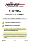
TYPE SPG-120/10
!
5
MADE FOR:
PROTECT
genset units with the possibility of indicating
or stopping in case of fault for:
DISPLAY
the following functions on the front:
- hour meter
- low oil pressure
- tachometer
- overtemperature
- oil pressure gauge
- battery recharge failure (alternator belt
- water or oil thermometer
breakage)
- generator voltage
- minimum fuel level
- generator current
- low cooling liquid level
(3 ammeters)
- generator overloading (does not replace
- generator apparent power
the thermomagnetic switch)
- generator frequency
- generator overfrequency
- battery voltage
- generator underfrequency
- fuel level
- generator undervoltage
- periodic maintenance indication
- battery overvoltage
- oil and battery indicators
- battery undervoltage
- protections intervention
- exceeding of programmed work time
- SMALL DIMENSIONS
- TEXT IN 5 LANGUAGES: ITALIAN, ENGLISH, FRENCH, GERMAN
AND SPANISH
- SIMULTANEOUS READING OF 6 INSTRUMENTS
- MOUNTING ALSO ON THE MACHINE
- DEGREE OF PROTECTION ON THE FRONT IP64
- POSSIBILITY OF CONNECTION TO PERSONAL COMPUTER
GB SPG-120/10
1
INSTRUCTIONS IN BRIEF
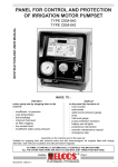
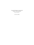
SPG-120/10 surveys the most important parameters of the engine and of the generator of a singlephase or three-phase genset unit, showing them on the alphanumeric display and stopping the engine if
there is an anomaly. An interface cable transmits the data to a personal computer, even at a distance.
OIL AND BATTERY
INDICATORS
On with key
turned to
automatic, they
switch off when
the genset unit is
running, oil
pressure and
battery recharge
system functioning normally.
ACOUSTIC ALARM
SWITCH-OFF
DISPLAY
·
PRESS BRIEFLY TO
SHOW THE
INSTRUMENTS.
PERIODIC MAINTENANCE
START KEY
(TO BE MOUNTED EXTERNALLY)
0
- REST
- MANUAL STOP
- RESET
OIL
INDICATOR
AUT.
BATTERY
INDICATOR
- DEVICE
SUPPLY
- PROGRAMMING
AVV. -
EMERGENCY
STOP
START GENSET
INSTRUMENTS
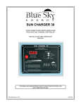
Shows on the alpha- THREE GENERATOR Compatible with the amperometric transformers of type 30/5, 40/5,
AMMETERS
50/5, 60/5, 80/5, 100/5, 200/5, 250/5, 300/5, 400/5, 500/5, 600/5,
numeric display the
800/5, 1000/5, 1200/5, 1500/5, 2000/5. Maximum reading of 2000A
three mains voltages
or 110% of the base scale current of the chosen transformer.
and the main para GENERATOR
meters of the engine
VOLTMETER
For single-phase or two-phase of nominal value up to 500 V~.
and the generator.
GENERATOR
From 0 Hz to 85 Hz for alternating voltages with amplitude greater
The data can be
FREQUENCY METER than 30 V~.
transmitted (by cable VOLTAMMETER
Displays apparent power up to 1500KVA
or GSM modem) to a FUEL LEVEL
Displays the percentage of fuel present in the tank.
personal computer.
INDICATOR
SIMULTANEOUS WATER OR OIL
Displays engine oil and water temperatures up to 140°C
READING OF THE
THERMOMETER
INSTRUMENTS
OIL PRESSURE
Displays engine oil pressure up to 6 bars
WITH ENGINE
GAUGE
RUNNING:
BATTERY
For voltages between 9 and 38 volt.
GENSET
VOLTMETER
VOLTMETER, FRE- HOUR METER
With four figures and a maximum reading of 9999. The hour meter
QUENCY METER,
numbers flash when it is necessary to perform the periodic mainteand THREE AMMEnance operations planned by the manufacturer of the genset unit.
TERS,HOURMETER TACHOMETER
Displays the number of engine revs up to 8500 rpm
7(&+1,&$/'$7$
Battery power supply:
Voltage supply:
Suitable for generators with
nominal voltage of
Consumption with engine stationary:
Max circuit consumption
Nominal insulation voltage
Terminal board of mains:
Terminal board of genset:
Terminal board of battery:
Maximum load on outputs
Degree of rear protection:
Degree of front protection:
Temperature range:
Weight:
Dimensions
Hole
Hour-meter:
Battery voltmeter:
Generator voltmeter:
Generator ammeters:
Frequency meter:
Tachometer
Voltammeter
Accuracy of oil pressure gauge, water
thermometer, fuel level indicator
Serial output parameters
2
12Vdc and 24Vdc
8 ÷ 32V
220 ÷ 450Vac ±10%; frequency 50 ÷ 60Hz
19mA at 12V
13mA at 24V
170mA at 12V
95mA at 24V
380V
450V
32V
5 (stopping), 7 (general alarm): 3W
IP20
IP 64
−10 ÷ +50 º C
350gr
144x96x49mm
88x136mm
4 digits
Max 38V, accuracy 2%
Max 450V, accuracy ±2%
Max 2400A, accuracy ±2%
0-85 Hz, accuracy ±0,1 Hz
0-8500 RPM accuracy ±10 RPM
Max 1500kVA, accuracy ±4%
2%
9600 baud, 8 bit data, 1 bit stop; no parity
GB SPG-120/10
OPERATION
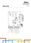
*(16(73527(&7,216
GENSET PROTECTION ENABLING
The genset unit protections are enabled in three ways:
• Immediately for battery undervoltage or overvoltage, overheating alarm, engine overheating, engine
overheating detected by thermostatic switch, all of the fuel control levels generator overfrequency, generator
overload alarm, generator overload and low radiator coolant level.
• 10 seconds after the threshold for the generator undervoltage and underfrequency has been reached;
• 20 seconds after the termination of the start-up impulse for the anomaly probes: Low oil pressure warning,
low oil pressure, generator overvoltage and recharge alternator fault
The intervention of the fault is displayed; it can cause the engine to be stopped and activates the general alarm.
SEE TABLE on page 5.
FAULT DISPLAY
W hen the engine is running the generator set instruments are shown.
W hen there is a fault, instead of the reading, the display shows the intervened fault message.
HOW TO SEE THE INSTRUMENT READINGS AGAIN
The measurements can be read by pressing key
for 1 second.
The display will resume showing the previous fault 20 seconds after the last pressing of the key.
FAULT RESET
The protection devices and all the stopped functions are re-activated by pressing the start key.
(1*,1(67233$*(
The device commands the stop in three ways:
·
By turning the start key onto “ZERO”
·
By protections intervention
·
By external emergency intervention.
The device adapts to two different stop systems:
·
By working the ELECTROMAGNET for 20 seconds which pulls the STOP lever
·
By cutting off power to the SOLENOID VALVE shutting off the flow of fuel.
*(1(5$/$/$50
This is produced by mounting an external optic and/or acoustic signal, linked to the appropriate terminal.
W hen key
is pressed, the general alarm is silenced.
35(9(17,9(0$,17(1$1&(
W hen preventive maintenance operations need to be carried out, the figures of the hour-meter flash while the
number of the intervened maintenance appears and LED
lights up.
The timing for the maintenance operations and the procedure for zeroing the time up maintenance indication
can be programmed by the manufacturer of the genset unit.
GB SPG-120/10
3
&20081,&$7,213257
5(027(',63/$<215(48(67
When the special adaptor cable is connected to a personal computer remote display is
possible, in various ways, using a program for the Windows operating system.
The instructions for use and loading are on the program disk.
4
GB SPG-120/10
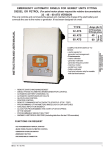
BASIC TABLE
*(1(5$725
6(7
3527(&7,21
',63/$<
,1)250$7,21
6
(
&
2
1
'
6
$
&
7
,
9
,
1
6
7
$
$ 1
7 7
,
2 2
1 )
7+5(6+2/'6
PROGRAMMING
6723
,17(59(17,21 )8 6
7
1 2
'(/$<
0 3
5
& 5
5(*8
/$7,21
),(/'
)$&7
25<
6(77,1*
$'-867
0(17
5$1*(
)$&725<
6(77,1*
7 (
,2 6
1 7
+
(
6(&21'6
$
%
/
(
5
2
*
5
$
0
(
*
8
/
$
7
,
2
1
)
$
&
7
2
5
<
BATTERY
UNDERVOLTAGE
IMMEDIATE
8÷12
(12V)
16÷24
(24V)
11 (12V)
22 (24 V)
1÷5
2
YES
BATTERY
OVERVOLTAGE
"
12÷18
(12V)
24÷36
(24V)
16 (12V)
32 (24V)
=
5
NOT
YES
WITHOUT
STOP
OVERHEATING
WARNING
"
90÷140° C
95° C
=
=
NOT
YES
WITHOUT
STOP
ENGINE
OVERHEATING
"
90÷140° C
100°C
=
=
YES
STOPS
OVERTEMPERATURE
DETECTED BY
THERMOSTATIC
SWITCH
"
=
=
=
IMMEDIATE
YES
STOPS
0÷99
10%
=
=
NOT
DOES NOT
STOP
0÷99%
1%
1÷5
3
YES
FUEL
RESERVE
"
DOES NOT
STOP
"
NO FUEL
LOW OIL
PRESSURE
WARNING
20 sec.
after
the end
of the
start-up
impulse
0÷6 bar
0,5 bar
1÷5
0
LOW OIL
PRESSURE
"
=
=
=
,17(59(17,212&&856:+(1
YES
WITH
STOP
Battery voltage remains lower than the
programmed threshold for the whole of
the intervention delay time
Battery voltage exceeds the
programmed threshold for the whole of
the intervention time
The temperature detected by the
transmitter exceeds the set threshold
The temperature exceeds the threshold
set by the thermostatic switch. No
programming is possible.
The fuel level controlled by a
rheostat float remains lower than the
programmed threshold
The fuel level remains lower than the
programmed threshold for the whole of
the intervention delay time
NOT
DOES NOT
STOP
The pressure detected by the transmitter
remains lower than the programmed
threshold for the whole of the
intervention delay time
IMMEDIATE
YES
STOP
The pressure is lower than the threshold
set by the pressure switch.
20 sec.
after
the end
of the
start-up
impulse
10 sec.
after
the
threshold is
exceeded
10 sec.
after
the end
of the
start-up
impulse
=
=
=
3
YES
YES
WITH
STOP
Alternator does not recharge the battery
and the intervention delay time has
elapsed.
80÷400 V
335V twophase
193V
singlephase
1÷10
3
YES
YES
WITH
STOP
Generator voltage remains lower than
the programmed threshold for the whole
of the intervention delay time.
440 V
TWOPHASE
254 V
SINGLEPHASE
0÷10
3
YES
YES
WITH
STOP
Generator voltage remains above the
programmed threshold for the whole of
the delay time.
GENERATOR
UNDERFREQUENCY
10 sec.
after
the
threshold is
exceeded
0÷60hz
0 Hz
0÷10
5
YES
YES
WITH
STOP
Generator frequency remains lower than
the programmed threshold for the whole
of the intervention delay time.
GENERATOR
OVERFREQUENCY
IMMEDIATE
51÷85hZ
72 (60Hz)
0÷5
2
YES
STOPS
GENERATOR
OVERLOAD
WARNING
"
0÷120%
(MAX
2400A)
47,5A
(TA 50/5)
0÷30
20
YES
DOES NOT
STOP
GENERATOR
OVERLOAD
"
0÷120%
(MAX
2400A)
50A
(TA 50/5)
0÷30
10
YES
RECHARGE
ALTERNATOR
FAULT
GENERATOR
UNDERVOLTAGE
GENERATOR
OVERVOLTAGE
LOW
RADIATOR
COOLANT
LEVEL
GB SPG-120/10
IMMEDIATE
100÷
500V~
60 (50Hz)
=
=
=
5
YES
YES
WITH
STOP
STOPS
Generator frequency remains above the
programmed threshold for the whole of
the intervention delay time
Generator current remains above the
programmed threshold for the whole of
the intervention delay time.
The cooling liquid falls below the
electrode and the intervention delay time
has elapsed.
(No programming is possible)
5
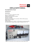
• TWO-PHASE VOLTMETERIC
• THREE-PHASE AMMETERIC
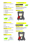
:,5,1*',$*5$0
OUTPUTS
MAX 3A
1
{
63*
GENERAL ALARM
STOP
SUPPLY
EMERGENCY
+
6
12
T
31
2 3
4 5
9 10
30
COMMUNICATION
PORT
CONNECT
DIRECTLY TO
THE (
)
BATTERY
TERMINAL
FUSE
5A
EMERGENCY
CLICK-DOWN
BUTTON
W
8 29
7
FOR THE CONNECTION OF
A SINGLE AMMETER USE
TERMINALS 75-77 AND
MOVE DIP-A SWITCH 4
TO 21
MAX
450 VAC
50/60 Hz
11
U V
75 76 77 78
FUSE
1A
MAX 1,5 m
MIN 2,5 mm
3
157
4
112
97
U V W
450 V MAX
GENERATOR
41
16
FUSE
15/54
5A
30
50
If the LOW COOLANT
LEVEL FUNCTION is not
used connect the
terminal 31 to ground
1
30
30 85
50
87
30
86
85
40
87
86
2/7
155
155
SCREW
ELECTRODES
ROD
ELECTRODE
W
B+
D+
COOLANT LEVEL PROBE
FOR RADIATORS WITH
PLASTIC EXPANSION TANKS
FOR RADIATORS WITH
METAL EXPANSION TANKS
,03257$17
28
USING A RECHARGE
BATTERY ALTERNATOR
HOOK UP THE DEFLECTOR
12 24 TO THE POSITION THAT
VOLT CORRESPONDS TO THE
NOMINAL VOLTAGE OF
THE BATTERY (12÷24V).
WITHOUT A RECHARGE
BATTERY ALTERNATOR DO
NOT HOOK UP THE
DEFLECTOR.
(BELT BREAKAGE)
YELLOW
RED
YELLOW
GRGB L C
+
R
+ LE
27
26
$&&(6625,(6
215(48(67
(1) START KEY
(2/7) ELECTROMAGNET OR
SOLENOID VALVE
(3) OIL PRESSURE SWITCH
(4) THERMOSTATIC SWITCH
(16) FUEL FLOAT
(97) OIL PRESSURE TRANSMITTER
(112)TEMPERATURE TRANSMITTER
(157)GENERAL ALARM INDICATOR
6
02817('21(1*,1(
(26) PERMANENT MAGNETS
CHARGE ALTERNATOR
(27) ALTERNATOR REGULATOR
(28) PRE-EXCITATION CHARGE
ALTERNATOR
(40) STARTING MOTOR
(41) BATTERY
GB SPG-120/10
352*5$00,1*
BEFORE ENABLING THE PROGRAMMING OF THE CONTROL PANEL,
CARRY OUT PROGRAMMING WITH THE ENGINE STATIONARY AND START KEY ON AUT (FIRST TRIGGER).
FOR PROGRAMMING ONLY SIMPLY CONNECT FASTONS 1-6-2-9.
QRUPDOO\LWLVUHDG\IRURSHUDWLRQZLWKMXVWWKHSURJUDPPLQJRIWKHDPSHURPHWULFWUDQVIRUPHUV
6723
6<67(0
6(/(&
7,21
%$7 *(1( *(1(
7(5< 5$725 5$725
92/
)5( 92/
7$*( 48(1&< 7$*(
(;&,
7(',1
6723
2102'(
9
(;&,
7(',1
'5,9(
02'(
+] 6,1*/(
3+$6(
9
+]
7+5((
3+$6(
DIP - A
DIP - B
12 24
VOLT
&+2,&(2)$03(520(75,&75$16)250(5
Amperometric transformer can be selected
from 30/5 up to 2000/5
21
Move DIP-B
switch 1
to21
1
21
1
AMP. TRANSFORMER
50/5
Press to choose
the value of the
amperometric
transformer.
PROGRAMMED
GEN. OVERLOAD
FAULT
95A
•GENERATOR OVERLOAD
FAULT
•GENERATOR OVERLOAD
Once the A.C. has been programmed the thresholds set
themselves automatically.
The FAULT threshold is set to 95%, the overload threshold
to 100% of the nominal value of the A.C.
To change the thresholds manually see page 17.
GENERATOR
OVERLOAD
100A
(0(5*(1&<386+%87721
Remove the jumper if the
emergency button is mounted
DIP-B1
R182
Never install the emergency
push-button linked to a stop
system which is inactive when
the unit is running
R181
This can be obtained in all operating
conditions, by mounting a push-button
(release).
(
/3
AMP. TRANSFORMER
0
100/5
$
;
(Press and wait until
the writing appears:
$8720$7,&&$/,%5$7,21$&
(0(5*(1&<67233$*(
Move DIP-B
switch 1
to2))
1
DIP-A1
$8720$7,&(;,7)520352*5$00,1*
THE POWER UNIT ACCEPTS COMPLETE PROGRAMMING ONLY
R184
R183
1
When 3 minutes have passed during which no switch programmers has been
moved and no keys have been pressed, the power unit will exit the
programming.
JP1
S3
To abandon an incomplete programming (without confirmation as shown by the written
item “PROGRAMMED”) move all the DIP-B switches to OFF.
5(6725(7,0(6$1'7+5(6+2/'6)$&725<352*5$00,1*
To restore all the factory-set programming:
ON
1 2 3 4 5 6 7 8
Move DIP-B
switches 1-3-5-7
to21
)2//2:,1*352*5$00,1*,61275(6725('
• LANGUAGE • MAINTENANCE • WORKING HOURS
PRESSURE AND TEMPERATURE TRANSMITTERS
TABLES • FUEL FLOAT CHOICE
GB SPG-120/10
ON
1 2 3 4 5 6 7 8
MOVE ALL THE
DIP-B SWITCHES
BACK TO 2)).
Press for at least
1 second, until the
writing STANDARD PROGRAMMING appears
7
LANGUAGE SELECTION
/$1*8$*(6(/(&7,21The language set up in the factory is ITALIAN, the languages that can be selected are: ENGLISH - SPANISH - GERMAN - FRENCH.
21
21
Move DIP-B
switch 8 to ON
8
6(/(&7/$1*8$*(
(QJOLVK
Press to
display
Move DIP-B
switch 8 to OFF
8
6(/(&7/$1*8$*(
(QJOLVK
Press and select the desired
language
Press and wait for
PROGRAMMED to be written
ENGINE PROGRAMMING
BATTERY UNDERVOLTAGE The engine does not stop.
Threshold
21
Move DIP-B
11 Volt
switch 2 to ON
2
Intervention
delay
2 sec
21
Move DIP-B
switch 2 to OFF
2
11 Volt
BATTERY
UNDERVOLTAGE
Press to
display
2 sec
Press when the arrow is next to
the parameter to be modified
Press and wait for
PROGRAMMED to be written
BATTERY OVERVOLTAGE
The protection device is factory-programmed to not stop. Non-adjustable intervention delay of 5 sec.
Threshold
21
21
Move DIP-B
Move DIP-B
16 Volt
switch 2 to OFF
switch 2 to ON
2
2
Engine
NO STOP stopping
16 Volt
BATTERY
OVERVOLTAGE
Press to
display
NO STOP
Press when the arrow is next to
the parameter to be modified
Press and wait for
PROGRAMMED to be written
ENGINE OVERTEMPERATURE INTERVENTION
The temperature is detected by the TEMPERATURE TRANSMITTER and is programmable. The protection device can be
set on two levels and intervenes when these are exceeded. The warning level is programmed only as a signal; the
other level is programmed to stop the engine (the overtemperature is also detected by the thermostatic switch, which always
causes the engine to stop).
ENGINE OVERHEATING WARNING
21
Move DIP-B
switch 2 to ON
2
Threshold
95°C
21
NO STOP
Engine
stopping
Move DIP-B
switch 2 to OFF
2
95°C
OVERHEATING
ALARM
NO STOP
Press to
display
Press and wait for
PROGRAMMED to be written
Press when the arrow is next to
the parameter to be modified
OVERHEATING
21
Move DIP-B
switch 2 to ON
2
21
Threshold
100°C
ENGINE
OVERHEATING
100°C
NO STOP
Press to
display
EXAMPLE
Press when the arrow is next to
the parameter to be modified
FUEL LEVEL. Variable-resistance float programming.
Threshold
21
Move DIP-B
1%
switch 2 to ON
2
Intervention
delay
NO FUEL
FUEL RESERVE
Move DIP-B
switch 2 to OFF
2
3 SEC.
STOP
Engine
stopping
Press to
display
Press and wait for
PROGRAMMED to be written
21
Move DIP-B
switch 2 to OFF
2
1%
3 SEC.
NO FUEL
Press when the arrow is next to
the parameter to be modified
STOP
Press and wait for
PROGRAMMED to be written
PROGRAMME ONE LEIVEL AT A TIME
8
GB SPG-120/10
ENGINE PROGRAMMING
LOW OIL PRESSURE WARNING (the pressure is detected by the pressure transmitter) is programmed as a signal and
does not stop the engine. (Low pressure detected by the pressure switch causes the engine to stop) .
21
Move DIP-B
switch 2 to ON
2
Threshold
21
0,5 Bar
Intervention
delay
Move DIP-B
switch 2 to OFF
2
1 Sec.
0,5 BAR
LOW OIL PRESSURE
WARNING
1 SEC.
Press to
display
Press and wait for
PROGRAMMED to be written
Press when the arrow is next to
the parameter to be modified
ALTERNATOR DOES NOT RECHARGE.
It is possible to programme the stop; it is factory-programmed to stop.
Move DIP-B
21
switch 2 to ON
2
STOP
21
Engine
stopping
Move DIP-B
switch 2 to OFF
2
RECHARGE
ALTERNATOR FAULT
Press to
display
STOP
Press and wait for
PROGRAMMED to be written
Press when the arrow is next to
the parameter to be modified
SETTING THE TACHOMETER. Do this with the engine running. Bring the engine to constant known revs (for example using a rev counter).
In this case the setting is carried out with the engine running.
21
1 2
Move DIP-B
switches 1 and 2 to ON
21
SET THE ENGINE REVS
ENGINE
3000
REVS
Move DIP-B
switches 1 and 2 to OFF
1 2
ENGINE REVS
SETTING THE
TACHOMETER
3000
Press to set the
engine revs
Press to
display
Press and wait for
PROGRAMMED to be written
If you do not have a rev counter accelerate the engine until the frequency meter shows 50Hz (60Hz) and calibrate the rev counter to:
3000 RPM (3600 RPM) for engines at 3000 revs/min ( 3600 revs/min)
1500 RPM (1800 RPM) for engines at 1500 revs/min ( 1800 revs/min) IT IS FACTORY-PROGRAMMED TO: 3000 RPM for gensets at 50 Hz
3600 RPM for gensets at 60 Hz
GENERATOR PROGRAMMING
GENERATOR UNDERVOLTAGE. The protection activates when the generator voltage continues to remain above the programmed value for
10 seconds.
The threshold set in the factory is 335 V with an intervention delay of 3 seconds.
Threshold
21
21
Move DIP-B
Move DIP-B
335 Volt
switch 2 to OFF
switch 2 to ON
2
2
Intervention
delay
3 sec.
NO STOP
Engine
stopping
335 Volt
GENERATOR
UNDERVOLTAGE
3 sec.
Press to
display
Press when the arrow is next to
the parameter to be modified
NO STOP
Press and wait for
PROGRAMMED to be written
GENERATOR OVERVOLTAGE. It is factory-programmed to stop.
21
2
Move DIP-B
switch 2 to ON
Threshold
440 Volt
Intervention
delay
3 SEC.
21
STOP
Engine
stopping
GENERATOR
OVERVOLTAGE
Press when the arrow is next to
the parameter to be modified
Move DIP-B
switch 2 to OFF
440 Volt
3 SEC.
Press to
display
GB SPG-120/10
2
STOP
Press and wait for
PROGRAMMED to be written
9
GENERATOR PROGRAMMING
GENERATOR UNDERFREQUENCY. In the factory the protection is excluded. To activate it, it is necessary to programme an intervention frequency other
than 0 Hz. The protection activates when the generator frequency remains continuously above the programmed value for 5 seconds.
21
2
Move DIP-B
switch 2 to ON
Threshold
0 Hz
Intervention
5
delay
SEC.
21
NO STOP
Engine
stopping
GENERATOR
UNDERFREQUENCY
Move DIP-B
switch 2 to OFF
2
0 Hz
5 SEC.
Press to
display
STOP
Press and wait for
PROGRAMMED to be written
Press when the arrow is next to
the parameter to be modified
GENERATOR OVERFREQUENCY. The threshold set in the factory is 60 Hz, suitable for plants at 50 Hz. In situations of OVERFREQUENCY
the engine is stopped. Non-programmable stoppage.
21
2
Move DIP-B
switch 2 to ON
Threshold
60 Hz
Intervention
delay
21
Move DIP-B
switch 2 to OFF
2
2 SEC.
60 Hz
GENERATOR
OVERFREQUENCY
2 SEC.
Press to
display
Press and wait for
PROGRAMMED to be written
Press when the arrow is next to
the parameter to be modified
GENERATOR OVERCURRENT . The protection can be regulated at two levels and intervenes when they are exceeded. Does not replace
the overload switch. The warning level acts only as a signal, while the other level can be programmed to stop the engine. For example, if
we choose transformer 100/5 the factory setting of the overcurrent will trigger the intervention at 100 A, but only when the amperometric
transformer withstands that current.
GENERATOR OVERLOAD WARNING.
21
2
Move DIP-B
switch 2 to ON
Threshold
95 AMP
Intervention
delay
21
Move DIP-B
switch 2 to OFF
2
20 SEC.
95 AMP.
GEN. OVERLOAD
FAULT
20 SEC.
Press to
display
STOP
Press and wait for
PROGRAMMED to be written
Press when the arrow is next to
the parameter to be modified
GENERATOR OVERLOAD
21
2
Move DIP-B
switch 2 to ON
Threshold
100 AMP
Intervention
delay
10 SEC.
21
STOP
Engine
stopping
GENERATOR
OVERLOAD
100 AMP
10 SEC.
STOP
Press and wait for
PROGRAMMED to be written
Press when the arrow is next to
the parameter to be modified
Press to
display
Move DIP-B
switch 2 to OFF
2
352*5$00$%/(7,0(
SECONDS
DESCRIPTION
REGULATION
RANGE
GENERAL ALARM INSERTION TIME
Number 350 means continual operation without time limits
GENERAL ALARM INSERTION TIME.
Number 350 means continual operation without time limits.
21
2
Move DIP-B
switch 2 to ON
GENERAL ALARM
INSERT. TIME
Press to
display
10
Time
350 sec.
Press when the arrow is next to
the parameter to be modified
10÷350
21
2
FACTORY
SETTING
350 (continual
operation)
Move DIP-B
switch 2 to OFF
350 sec.
Press and wait for
PROGRAMMED to be written
GB SPG-120/10
NOTICES
Used only to show the principal parameters of a genset unit and to survey it during its operation, commanding its
stoppage if there is an anomaly.
Constructed to be installed mounted in dashboards, electric panels ecc.
Warning: Components carrying dangerous voltage levels
Only assigned and suitably trained personnel are allowed access to the instrument. No maintenance operations
are permitted unless the plant is disconnected from the mains and the battery. As an additional safety measure,
the plant phases should be short-circuited and earthed.
Not withstanding the above, only assigned and trained personnel can perform the following operations with the
plant receiving power:
- visual inspection of the instrument connections and markings;
- measurement of the voltage and/or current;
- programming of the functions.
These interventions, however, must be performed using equipment which ensures appropriate levels of electrical protection.
Warning:
Adhere closely to the following advice
- When making connections always follow the instructions and the Wiring Diagram on page 6.
- Any interventions on the unit must be performed with the motor stationary and terminal 50 of the starting motor
disconnected.
- Check that the consumption of the connected equipment are compatible with the described technical characteristics.
- Install in such a way that there is always adequate heat disposal.
- Always install under other equipment which produces or spreads heat.
- Where the instrument can receive strong vibrations or knocks.
- Make sure that no copper conductor cuttings or other waste material fall inside the equipment.
- Never disconnect the terminals of the battery with engine running.
- Never use a battery charger for the emergency start-up; the engine could be damaged.
- In order to safeguard people and equipment, before connecting an external battery charger, disconnect the electrical
system terminals from the battery poles.
THIS MULTI-INSTRUMENT IS NOT SUITABLE FOR OPERATING IN THE FOLLOWING CONDITIONS:
- Where the environmental temperature is outside the limits indicated in the technical sheet.
- Where the air pressure and temperature variations are so rapid as to produce exceptional condensation.
- Where there are high levels of pollution caused by dust, smoke, vapour, salts and corrosive or radioactive particles.
- Where there are high levels or heat from radiation caused by the sun, ovens or the like.
- Where attacks from mould or small animals are possible.
- Where there is the risk of fire or explosions.
- Where the instrument can receive strong vibrations or knocks.
ELECTROMAGNETIC COMPATIBILITY
This instrument functions correctly only if inserted in plants which conform with the CE marking standards; it meets the
exemption requirements of the standard EN50082-2 but it cannot be excluded that malfunctions could occur in extreme cases
due to particular situations.
The installer is responsible for checking whether the levels of disturbance are above those consented by the regulations.
CONDUCTION AND MAINTENANCE
The following maintenance operations should be performed every week:
- check that the indicators function;
- check the batteries;
- check that the conductors are tight, check the condition of the terminals.
UNLESS WE MAKE A WRITTEN DECLARATION STATING THE CONTRARY, THIS EQUIPMENT IS NOT SUITABLE FOR
USE AS A CRITICAL COMPONENT IN EQUIPMENT OR PLANTS RESPONSIBLE FOR KEEPING PERSONS OR OTHER
LIVING BEINGS ALIVE.
YOUR ELECTRICAL TECHNICIAN CAN ASK ANY QUESTIONS ABOUT
THIS INSTRUMENT BY TELEPHONING OUR TECHNICIAN
GB SPG-120/10
11
ACCESSORIES AVAILABLE ON REQUEST
TO READ THE DISPLAY INDICATIONS (SPG-120/10)
ON VIDEO (PC)
DISTANCES UP TO 11 m
SERIAL CABLE FOR
PROGRAMMING
TRANSFER
TYPE ZC-191
code
07.01.37
KIT VIDEO KPC-120
code 07.01.34
INCLUDING THE FOLLOWING
PARTS:
ADAPTOR CABLE FOR
COMPUTER
Type ZC-174
code 07.01.25
SERIAL CABLE
Type ZC-175
code 07.01.03
PROGRAM FOR WINDOWS
Type ZW-120
code 07.01.22
DISTANCES UP TO 515 m
REMOTE
KIT VIDEO KPC-106 Code 07.01.35
INCLUDING THE FOLLOWING
PARTS:
ADAPTOR CABLE
FOR COMPUTER ZC-174
Code 07.01.25
CONVERTOR TRANSMITTER
(COMPLETE WITH POWER
PACK)
Type ZT-105
Code 07.01.07
CONVERTOR RECEIVER
(COMPLETE WITH POWER
PACK)
Type ZR-105
Code 07.01.06
TELEPHONE WALL-SOCKET
Type ZP-105
Code 07.01.05
TELEPHONE CABLE
Type ZC-181
Code 07.01.04
PROGRAM FOR WINDOWS
Type ZW-115
Code 07.01.22
FOR THE CONNECTIONS AND THE LENGTH OF THE CABLES SEE PAGE 4
SUPPLIED ACCESSORIES
MOBILE SOCKET
Type PMO180-181-235-246
ORDERING DATA
type SPG-120/10
code 24.20.07
Code 80.42.84
CONFORMITY DECLARATION
The company Elcos s.r.l. assumes full responsabilty for declaring that the equipment:
type
SPG-120/10
manufactured in the year
2004
used in the ways and for the purposes described in the enclosed instruction
and user manual is in conformity with the following directives:
· 73/23/CEE concerning electrical materials used within certain voltage limits
· 89/336/CEE concerning electromagnetic compatibility
both modified by the directive 93/68/CEE
because it is built and functions in accordance with the harmonized Standards:
- EN 61010-1 safety requirements for electrical measuring and control equipments and
for
laboratory use
- EN 61326-1 electrical measuring, control and laboratory equipment.
Electromagnetic compatibility requirements.
6UO
12
Parma, 20/01/2003
President
Ruggero Lombardo
GB SPG-120/10