1
2
Toll Free Technical Support
Soutien technique sans frais
1 888 577-6274
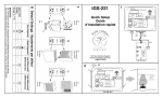
Quick Setup
Guide
d'installation rapide
1
iGS-111
Default Settings / Ajustements par défaut
IMPORTANT
For a safe use of the iGS-111, read the Security and Maintenance section in the User Manual.
Pour une utilisation sécuritaire du iGS-111, lire la section Sécurité et entretien du Manuel d'utilisation.
3
4
5
IMPORTANT:
1 circuit 15A-120 VAC per/par iGS-25
6
INTEGRATED CONTROLLER FOR
TEMPERATURE AND HUMIDITY
Why use many climate controllers when a single one
can perfectly manage the garden's temperature and humidity?
THE IGS-DCS - DRY CONTACT SWITCHER
The iGS-DCS is a switch relay that operates from a standard 110-120V electrical output. It
activates a control loop that can operate air conditioning unit, heat pump, ventilators,
humidifier, dehumidifier or “2 wires” devices connected to a less than 90V ac circuit or a
24V dc circuit. The iGS-DCS, when connected to a 110-120V climate controller’s output,
replaces any thermostat or hygrometer equipped with “2 wires”. These “2 wires” once
removed from the thermostat or hygrostat can be reassigned to the iGS-DCS’ electric
screw terminals. Then, plugged into the proper controller’s activated output, the iGS-DCS
relay will connect both electric terminals and enable the equipment. Please note that it may
be necessary to use an extension cord to avoid hindering other controller’s output.
novabiomatique.com
Manufactured in North America
T: 418 856-6274 F: 418 856-6239
Technical Support: 1 888 577-6274
TABLE OF CONTENTS
1.
DESCRIPTION
1. Description ......................................................................................................... 4
2. Connection and Installation.............................................................................. 4
Components ....................................................................................................... 4
Connection Scheme ........................................................................................... 5
PLUG’N’GROW’s iGS-111 combines precision and simplicity!
Why use many climate controllers when a single one can perfectly manage the
garden's temperature and humidity?
Connection Instructions ...................................................................................... 6
∀
Recommended Equipments for an Optimal Use of the iGS-111 ........................ 6
∀
Connecting an Alarm System ............................................................................. 7
∀
-
Installation and Security Notice .......................................................................... 7
3. Settings Ajustement .......................................................................................... 8
Control Panel Description................................................................................... 8
Initialization......................................................................................................... 9
Relative Humidity Settings Adjustment [% RH] .................................................. 9
Temperature Settings Adjustment [Temp °C / °F] ............................................ 11
Intelligently manages 4 actions: heating, cooling (AC or fan), humidifying
and dehumidifying.
Prioritizes actions according to a logical sequence! No more need to
coordinate many controllers together!
Allows temperature and humidity's differential adjustment for:
∀
∀
∀
∀
∀
A precise comfort zone for plants;
Avoiding contradictory actions like heating and cooling at the same time;
More energy savings;
A better durability of the equipments.
Feeds up to 30 amps of controlled equipments (110-120V).
Ready to use, just adjust your set points!
Offers a 24 hours log to know your garden’s conditions.
Hassle free 3 years warranty.
7 days free technical support.
novabiomatique.com
Time Clock Setting ........................................................................................... 14
24 Hours Log .................................................................................................... 14
Differential ........................................................................................................ 15
Alarm ................................................................................................................ 16
2.
CONNECTION AND INSTALL ATION
C O MPO NE N TS
1 control module
1 connection module
2 iGS-25
1 AC adaptor
4. Sequence of Actions ....................................................................................... 18
Table of Sequence of Actions........................................................................... 18
5. Displayed Messages and Solutions............................................................... 19
Information Messages (Advice) ........................................................................ 19
Error Messages ................................................................................................ 20
Alarm Messages............................................................................................... 20
Reset Procedure............................................................................................... 20
6. Sensors Calibration......................................................................................... 21
Relative Humidity and Temperature Sensors Calibration................................. 21
7. Security and Maintenance .............................................................................. 22
Air Filter ............................................................................................................ 22
Water Splashing ............................................................................................... 22
Electrical Specifications.................................................................................... 23
8. Warranty ........................................................................................................... 24
Step-By-Step Warranty and Repairs Implementation....................................... 24
iGS-111
© 2010 - Nova Biomatique inc. PLUG’N’GROW∀
3
3 Ethernet cables (RJ45)
1 spare filter
4
© 2010 - Nova Biomatique inc. PLUG’N’GROW∀
iGS-111
C O NNE CTI O N S CHE ME
C O NNE CTI O N I NS T RU C TI O NS
For more details, please refer to Quick Setup Guide.
CONNECTING THE CONTROL MODULE TO THE CONNECTION MODULE
∀
∀
Connect the two wires cable from the connection module (Input 1) to the
control module’s terminal block. The red wire connected to the right terminal;
the black wire to the middle terminal.
Connect one of the Ethernet cable’s (RJ45) male connector into the female
connector located underneath the control module and the other male
connector in the connection module’s female connector (Input 2).
CONNECTING THE CONNECTION MODULE TO EACH IGS-25
∀
∀
Connect one male connector of each Ethernet cable into the connection
module’s female connectors (A and B).
Connect the other male connector of the Ethernet cables into each iGS-25’
female connectors.
Each iGS-25 can be replaced with an iGS-50 or the other way around. The
A connector from the connection module supplies the control module with
electricity. The iGS-25 linked to the A connector must be connected to an
AC adaptor (see scheme page 5). The iGS-50 linked to the A connector does
not require an AC adaptor.
CONNECTING THE EQUIPMENTS TO EACH IGS-25
∀
Connect the equipments to the iGS-25 following these indications and
looking at the scheme on page 5.
Output A1: Heating equipment
Output A2: Cooling equipment
Output B1: Humidifying equipment
Output B2: Dehumidifying equipment
Equipments which use other voltage then 110-120V may be controlled by the
iGS-221 by using an iGS-DCS (see back of cover page).
R E CO MM E N D E D E Q UI P ME N TS FO R A N O P TI M A L US E O F TH E I G S - 1 11
The iGS-111’s program is designed to control specific equipments. It is
recommended to use the following equipments for an optimal control:
Output A1: Heater
Output A2: Air conditioner (with setting knobs), or other cooling device*
Output B1: Humidifier, fogging device
Output B2: Dehumidifier
* Air conditioners with a built in digital keyboard cannot be controlled by the iGS111. However, it can independently be operated to reduce garden’s excessive
heat. To achieve this, set the air conditioner 1 or 2°C (2 to 4°F) above the iGS111’s adjusted temperature settings. A temperature sensor’s calibration is
suggested on your iGS-111 so both devices have equivalent temperature
readings (see Relative humidity and temperature sensors calibration on
page 21).
iGS-111
© 2010 - Nova Biomatique inc. PLUG’N’GROW∀
5
6
© 2010 - Nova Biomatique inc. PLUG’N’GROW∀
iGS-111
An intake/exhaust fan can be used for cooling in output A2. Please note that this
output might be on at the same time as the humidifying or dehumidifying
equipments. Also, depending on the outside weather, ventilation could not be
the ideal way to get an optimal climate control in the garden.
3.
SETTINGS AJUSTEMENT
C O N TRO L P A NE L D E S CRI PTI O N
C O NNE CTI NG A N A L A RM S YS T E M
The iGS-111 allows the connection to an alarm system, such as the iMS-100
from PLUG’N’GROW. See the Alarm section on page 16 for more information.
I NS TAL L A TI O N A N D S E C U RI TY NO TI CE
DANGER: To reduce risks of fire hazards or electrical shocks, attentively read
the following instructions before feeding the system with electricity.
SAFE INSTALLATION OF THE IGS-25
All iGS-25 have to be plugged in a 120V-15 A outlet. Each iGS-25 can support a
maximal load of 15 A. In order to take advantage of 15 A for each iGS-25, it is
important to use 2 electrical outlets on 2 separate electrical circuits. The
equipments’ total load must not exceed the electrical circuit capacity.
SAFE INSTALLATION OF THE CONTROL MODULE AND THE CONNECTION
MODULE
4 digits display:
The display shows different data: current room conditions, time, control module’s
settings and more.
The control module must be fixed to a vertical wall with 4 screws. It is
recommended to locate the control module at the plants’ height and at a
representative location for the conditions’ measurements. Also, the light sensor
(photocell), located in the bottom right corner, must be able to detect the
presence or absence of light.
2 climate parameters:
∀
[% RH]
∀ [Temp °C / °F]
The connection module also must be fixed on a vertical wall with 2 screws. For a
long distance connection, it is possible to replace the cables linking the iGS-25
and the connection module with other Ethernet cables with a maximal length of
50 feet. However, it is not recommended to use a cable longer than the one
included between the control module and the connection module.
(Relative humidity)
(Temperature)
5 applicable functions for each climate parameter:
∀
∀
∀
∀
∀
[Day Setpoint / Time]
[Night Setpoint]
[Differential]
[Alarm]
[24-Hour Log]
4 keys for selection:
∀ SELECT SENSOR: Repeatedly press this key to select a parameter.
∀ MODIFY: Repeatedly press this key to select a function.
∀ UP and DOWN ARROWS: Press to modify current value shown on the
display (optional to certain menus or operating modes).
Light indicators:
Light indicators are placed beside each parameter or function and are on (lit)
when a parameter or function is selected. In some cases, the light indicators
might flash.
Light sensor:
The control module has a built in sensor to detect the presence or absence of
light. Depending on the plant’s needs, the set point for light [Day Setpoint/Time]
and dark [Night Setpoint] periods may be different for each parameter.
iGS-111
© 2010 - Nova Biomatique inc. PLUG’N’GROW∀
7
8
© 2010 - Nova Biomatique inc. PLUG’N’GROW∀
iGS-111
Differential adjustment
I NI TI AL I ZA TI O N
For more information, see the Differential section on page 15.
When the controller is initialized, the following elements appear on the display:
∀
∀
The model (e.g.: P111) followed with the controller’s version (e.g.: S1.10);
Then, the time followed by an informative message (Adv), indicating that the
controller was unplugged for a while. For more information, see the
Displayed Messages and Solutions section on page 19.
The equipments’ activation starts only after a 30 seconds countdown.
R E L A TI V E HU MI DI T Y S E T TI N G S A DJ US T ME NT [% R H]
To adjust the set points for this parameter [% RH], repeatedly press SELECT
SENSOR until the light indicator is on at [% RH].
The display shows the current relative humidity measurement. A flashing display
means that an output associated with this parameter is active.
Once the light indicator is on at [Night Setpoint]:
∀ Press MODIFY again and hold the key until the
letter “L” (low), followed by a numerical value,
appears on the display (approximately
3 seconds). The light indicator will flash at
[Differential].
∀ To adjust the low differential (L), press the
ARROW keys to modify the current value; hold
down the key for a faster scroll of the values.
Press MODIFY to save the modification and
continue with the high differential (H)
adjustment.
∀ Press the ARROW keys to modify the high differential’s current value; hold
down the key for a faster scroll of the values.
∀ Press MODIFY to save the modification and continue to the next function.
To adjust the functions related to relative humidity, press MODIFY. The light
indicator is on at the selected function.
[DIFFERENTIAL]
[DAY SETPOINT]
This function is not active on the iGS-111. Do not take the displayed value in
consideration.
Relative humidity (%) adjustment during light
period
[ALARM]
Alarm – Relative humidity’s low and high limits adjustment
Once the light indicator is on at [Day Setpoint]:
∀ Press the ARROW keys to modify the current
value; hold down the key for a faster scroll of
the values.
∀ Press MODIFY to save the modification and
continue to the next function.
For more information, see the Alarm section on page 16.
Once the light indicator is on at [Alarm]:
∀ The letter “L”, followed by a numerical value,
appears on the display.
∀ To adjust the relative humidity’s low limit (L),
press the ARROW keys to modify the current
value; hold down the key for a faster scroll of
the values. Press MODIFY to save the
modification and continue with the relative
humidity’s high limit (H) adjustment.
∀ Press the ARROW keys to modify the current
value; hold down the key for a faster scroll of
the values.
∀ Press MODIFY to save the modification and continue to the next function.
[NIGHT SETPOINT]
Relative humidity (%) adjustment during dark
period
Once the light indicator is on at [Night Setpoint]:
∀ Press the ARROW keys to modify the current
value; hold down the key for a faster scroll of
the values.
∀ Press MODIFY to save the modification and
continue to the next function.
iGS-111
© 2010 - Nova Biomatique inc. PLUG’N’GROW∀
9
10
© 2010 - Nova Biomatique inc. PLUG’N’GROW∀
iGS-111
[24-HOUR LOG]
[DAY SETPOINT]
Access to the 24 hours log
Temperature (°C / °F) adjustment during light
period
For more information, see the 24 Hours Log section on page 14.
Once the light indicator is on at [Day Setpoint]:
∀ Press the ARROW keys to modify the current
value; hold down the key for a faster scroll of
the values.
∀ Press MODIFY to save the modification and
continue to the next function.
Once the light indicator is on at [24-Hour Log]:
∀ The display shows a definite time (clock) and the
following elements for that specific time:
o “Lo”, followed by a numerical value
corresponding to the lowest relative humidity
level measurement.
o “avg”, followed by a numerical value
corresponding to the average relative
humidity level measurements.
o “Hi”, followed by a numerical value
corresponding to the highest relative humidity
level measurement.
∀ Press the DOWN ARROW key to go back in the last 24 hours or the
UP ARROW key to go up to the most recent information.
∀ Press MODIFY to quit this function.
[NIGHT SETPOINT]
Temperature (°C / °F) adjustment during dark
period
Once the light indicator is on at [Night Setpoint]:
∀ Press the ARROW keys to modify the current
value; hold down the key for a faster scroll of
the values.
∀ Press MODIFY to save the modification and
continue to the next function.
T E MPE RA T U RE S E T TI NG S A DJ US TM EN T [ TE M P °C / °F]
Differential adjustment
To adjust the set points for this parameter [Temp °C / °F], repeatedly press
SELECT SENSOR until the light indicator is on at [Temp °C / °F].
For more information, see the Differential section on page 15.
The display shows the current temperature measurement. A flashing display
means that an output associated to this parameter is active.
Once the light indicator is on at [Night Setpoint]:
∀ Press MODIFY again and hold down until the
letter “L”, followed by a numerical value,
appears on the display (approximately
3 seconds). The light indicator will flash at
[Differential].
∀ To adjust the low differential (L), press the
ARROW keys to modify the current value; hold
down the key for a faster scroll of the values.
Press MODIFY to save the modification and
continue with the high differential (H)
adjustment.
∀ Press the ARROW keys to modify the high differential’s current value; hold
down the key for a faster scroll of the values.
∀ Press MODIFY to save the modification and continue to the next function.
To adjust the functions related to temperature, press MODIFY. The light
indicator is on at the selected function.
Changing the temperature units: Celsius or Fahrenheit
Once the light indicator is on at [Temp °C / °F]:
∀ Repeatedly press the MODIFY key until all light
indicators are off in the functions menu.
∀ Press MODIFY again and hold down the key until
“CELS” or “FAHr” appears on the display.
∀ Release the key to activate the new temperature
unit. If “CELS” appeared on the display, unit is
now in Celsius; if “FAHr” appeared, unit is now in
Fahrenheit.
∀ Repeat steps above to alternate between units.
iGS-111
© 2010 - Nova Biomatique inc. PLUG’N’GROW∀
11
12
© 2010 - Nova Biomatique inc. PLUG’N’GROW∀
iGS-111
[DIFFERENTIAL]
T I M E C L O CK S E T TI N G
This function is not active on the iGS-111. Do not take the displayed value in
consideration.
[ALARM]
The controller does not rely on clock to operate but rather on light and dark
periods detected from the light sensor (photocell). The accuracy of the time on
the clock does not affect the controller’s proper functioning.
Alarm – Temperature’s low and high limits adjustment
However, time setting is essential for a good 24 hours log interpretation.
For more information, see the Alarm section on page 16.
For more information, see below the 24 Hours Log section.
Once the light indicator is on at [Alarm]:
∀ The letter “L”, followed by a numerical value,
appears on the display.
∀ To adjust the temperature’s low limit (L), press
the ARROW keys to modify the current value;
hold down the key for a faster scroll of the
values. Press MODIFY to save the modification
and continue with the temperature’s high
limit (H) adjustment.
∀ Press the ARROW keys to modify the current
value; hold down the key for a faster scroll of
the values.
∀ Press MODIFY to save the modification and continue to the next function.
To set the time
∀
∀
∀
∀
∀
Repeatedly press SELECT SENSOR until the
light indicators are simultaneously on at [% RH]
and [Temp °C / °F].
Press MODIFY to select [Day Setpoint / Time].
Press the UP ARROW key to set the hours;
hold down the key for a faster scroll of the
values.
Press the DOWN ARROW key to set the
minutes; hold down the key for a faster scroll of
the values.
Press MODIFY to save the settings.
Please note that the controller uses a 24 hour clock (e.g.: 13:00 = 1:00 pm).
[24-HOUR LOG]
2 4 H OU RS L O G
Access to the 24 hours log
The 24 hours log is useful for:
∀ detecting defective equipments or intermittent problems;
∀ knowing your garden’s conditions in the last 24 hours;
∀ following climatic conditions to learn more about plants.
For more information, see the 24 hours log section on page 14.
Once the light indicator is on at [24-Hour Log]:
∀ The display shows a definite time (clock) and
the following elements for that specific time:
o “Lo”, followed by a numerical value
corresponding to the lowest temperature
level measurement.
o “avg”, followed by a numerical value
corresponding to the average temperature
level measurements.
o “Hi”, followed by a numerical value
corresponding to the highest temperature
level measurement.
∀ Press the DOWN ARROW key to go back in the last 24 hours or the UP
ARROW key to go up to the most recent information.
∀ Press MODIFY to quit this function.
iGS-111
© 2010 - Nova Biomatique inc. PLUG’N’GROW∀
The 24 hours log keeps in memory the measured values during the last
24 hours. The controller calculates for every one hour period the minimum
(“Lo”), the maximum (“Hi”) and the average (“avg”) measurements for each
parameter (% RH, Temp). The displayed values represent the measurements
taken in the hour preceding the one displayed (e.g.: 23:00 = measurements
between 10:00 pm and 11:00 pm).
It is important to set the time on your controller to get the log’s information
synchronised with real time (see Time Clock Setting section on page 14). To get
access to the 24 hours log, see pages 11 and 13 in the Settings Adjustment
section.
13
14
© 2010 - Nova Biomatique inc. PLUG’N’GROW∀
iGS-111
D I F FE R E N TI A L
A L A RM
The iGS-111 differential represents the climate’s variation around the set point.
In other words, the differential is the range between the values at which the
controller shuts off an equipment and at which the controller turns on the
opposite action equipment (e.g.: heater and air conditioner). The differential
contains an inferior part and a superior part from the set point. To ease the
display’s reading, the inferior differential (Low) is identified with an “L” and the
superior differential (High) is identified with an “H”. E.g.: For relative humidity, an
inferior differential of 3% will display as “L3” and a superior differential of 3% as
“H3”.
In order to be informed of any problem with the relative humidity or temperature
control, it is possible to designate low and high limits for these parameters to
trigger the alarm of the iGS-111. As soon as the ambient conditions drop down
lower than the low limit or exceed the high limit, the alarm will be activated: a
message (Alr X) will be displayed and the dry contact on the alarm connector
(connection module) will be activated as well. To fully take advantage of these
alarm options, the iGS-111 must be connected to a compatible alarm system
(0.6 A @ 120 Vac or 2A @ 30 Vdc), such as the PLUG’N’GROW automatic
dialer iMS-100 (not included).
63%
TWO ALARM MODES AVAILABLE
Mode A
Higher part
(H3)
Safe connection - triggers the contact when any of these three conditions is met:
60%
SET POINT
Lower part
∀
∀
∀
(L3)
57%
A power outage, a power supply or any component failure;
A sensor or memory failure;
Ambient conditions have reached the relative humidity or temperature’s low
or high limits.
Mode B
Differential levels recommended for relative humidity and temperature
control
Regular connection - triggers the contact when any of these two conditions is
met:
For temperature control, the recommended differential value for low and high
differentials is 1.0 °C (1.8 °F): “L1.0” and “H1.0” in Celsius and “L1.8” and “H1.8”
in Fahrenheit. For the relative humidity control, the recommended differential
value for the low and high differentials is 3 %: “L3” and “H3”. However, you can
modify these values to better suit your garden’s environment (see Differential
adjustment sections on pages 10 and 12).
∀
∀
Using a differential avoids that an equipment turns on at the same time as the
opposite action equipment turns off (e.g.: heater and air conditioner). Generally,
a small differential allows more stable conditions but can also cause waste of
energy and wear off the equipment faster. It is important to find the right
settings. Trial and error is the only sensible procedure to find out.
Alarm system connection
Mode B is not a safe connection. If the alarm relay or triggering circuit fails, the
alarm might not be transmitted.
∀
∀
∀
iGS-111
© 2010 - Nova Biomatique inc. PLUG’N’GROW∀
15
A sensor or memory failure;
Ambient conditions have reached the relative humidity or temperature’s low
or high limits.
16
Unplug the controller.
The alarm connector is located underneath the connection module.
Referring to the picture, connect the alarm system’s wires to the terminal
corresponding to the selected mode (Mode A = terminal Com + A; Mode B =
terminal COM + B).
Plug the controller.
© 2010 - Nova Biomatique inc. PLUG’N’GROW∀
iGS-111
Alarm mode adjustment (A or B)
∀
∀
∀
∀
∀
∀
4.
Repeatedly press the SELECT SENSOR key until the light indicator is on at
[Temp °C / °F] or [% RH].
Repeatedly press the MODIFY key until the light indicator is on at [Alarm].
The letter “L”, followed by a numerical value, is displayed.
Press MODIFY again and hold down the key until the letter “A” or “b”
appears on the display (mode A or B). The light indicator is flashing at
[Alarm].
Press the ARROW keys to select the alarm mode.
Press MODIFY to save the modification and continue to the next function.
To quit, repeatedly press MODIFY until all light indicators are off in the
functions menu.
To modify the relative humidity’s low and high limits, see the section Alarm
– Relative humidity’s high and low limits adjustment on page 10.
To modify the temperature’s low and high limits, see the section Alarm –
Temperature’s high and low limits adjustment on page 13.
To deactivate the iGS-111’s alarm functions, adjust the relative humidity and
temperature’s low and high limits to values that will never be reached and that
are different than 0.
SEQUENCE OF ACTIONS
To control the different equipments plugged in the iGS-25, the iGS-111 uses a
non modifiable internal programming. This programming allows the controller to
intelligently manage the 4 equipments, prioritizing a logical sequence of actions.
The following table sums up many possible situations and the outputs that will
be activated in each case. The controller constantly monitors the situation and
chooses the correct action as needed.
T A B L E O F S E Q UE N CE O F A C TI O NS
Outputs
Actions
A1
A2
Heating
Cooling
B1
Humidifying
B2
Dehumidifying
ACTIVATED OUTPUTS
Actions
Immediate activation
Humidifying
Dehumidifying
B1
B2
Heating
A1
Cooling
Activation after 5 min
A2
Humidifying, heating
B1, A1
Humidifying, cooling
A2
B1
Dehumidifying, heating
Dehumidifying, cooling
A1
A2
B2
B2
Example:
5 min
Dehumidifying, heating:
A1
B2
In a growing environment, the relative humidity level is too high and the
temperature is too low; the iGS-111 is in a situation where it needs to dehumidify
and heat. First, the controller will activate the heating equipment (A1). If the
desired temperature is not reached after 5 minutes and the heat has not allowed
to dehumidify enough, the dehumidifying equipment (B2) will be activated
(working at the same time as the heating equipment) until the desired humidity
level is reached.
Oppositely, if the desired temperature is reached after 3 minutes only, and the
humidity level is still too high, the heating equipment (A1) will shut off and the
dehumidifying equipment (B2) will immediately be activated.
iGS-111
© 2010 - Nova Biomatique inc. PLUG’N’GROW∀
17
18
© 2010 - Nova Biomatique inc. PLUG’N’GROW∀
iGS-111
5.
E R RO R M E S S A G E S
DISPLAYED MESSAGES AND SOLUTIONS
I NF O RMA TI O N ME S S A G E S ( A D V I CE )
Code
Cause
Solution
Err 1
A key from the keyboard is
pressed at power up.
If a key is stuck in, call technical support at
1 888 577-6274.
Verify your settings to
validate that the
recovered data are
exact to your
adjustments.
Err 4
Temperature/humidity sensor
is defective.
Err 6
Automatic recovery has failed
after intermittent fault.
Disconnect and reconnect the controller or do
a reset. See Reset Procedure at the end of this
section. If the problem persists, call technical
support at 1 888 577-6274.
At power on, the time is
displayed. The message
disappears by pressing the
MODIFY or SELECT
SENSOR key. The
24 hours log has been
erased for the power
outage duration.
Verify and adjust the
time if needed. See
Time Clock Setting
section on page 14.
A L A RM ME S S A G E S
At power on, the time is
displayed. For a long
power outage, it is most
likely that time adjustment
is needed. Message
disappears when the time
clock is adjusted. The
24 hours log has been
totally erased.
Adjust the time clock
since data have been
lost due to the long
power outage which
has drawn all current
from the rechargeable
backup battery. See
Time Clock Setting
section on page 14.
Code
Cause
Effects on controller
Adv 3
Automatic system
recovery has
completed successfully
after intermittent fault.
The message disappears
by pressing MODIFY key.
Adv 6
The system has
restarted after a short
power outage of less
than 2 hours.
Adv 7
The system has
restarted after a power
outage lasting between
2 and 36 hours.
Adv 8
The system has
restarted after a long
power outage of more
than 36 hours.
Solution
Code
Cause
Alr 1
Relative humidity’s low limit
has been reached.
Alr 2
Relative humidity’s high
limit has been reached.
Alr 3
Temperature’s low limit has
been reached.
Alr 4
Temperature’s high limit
has been reached.
Effect on controller
The message
disappears once the
conditions return
between the limits set
by the user. The
alarm’s dry contact is
activated.
Solution
Verify room conditions
or adjust the alarm’s
limits. See sections
Alarm – Temperature’s
high and low limits
adjustment and Alarm
– Relative humidity’s
high and low limits
adjustment on
pages 10 and 13.
R E S ET P R O C E DU R E
To reset the controller to factory default settings, follow the steps below:
∀
∀
∀∀
∀
iGS-111
© 2010 - Nova Biomatique inc. PLUG’N’GROW∀
19
20
Disconnect the Ethernet cable (RJ45) from the connector located
underneath the control module iGS-111.
Simultaneously press the UP and DOWN ARROWS and keep pressed while
reconnecting the Ethernet cable.
∋(.5∀605./∀%∀−13.8105(/∀/.0,4∀#9999∃∀(22,(3∀10∀5−,∀+.42/(7∀#()165∀&∀4,∗10+4∃∀
before releasing the ARROW keys.
The controller will restart: all settings are restored except altitude, time and
the 24 hours log.
© 2010 - Nova Biomatique inc. PLUG’N’GROW∀
iGS-111
6.
SENSORS CALIBRATION
7.
The iGS-111 includes 2 climate sensors: one for the temperature and a second
one for relative humidity. Each of them can be independently calibrated without
affecting the other.
SECURITY AND M AINTENANCE
A I R FI L TE R
The controller is equipped with an internal fan
that allows a faster air sampling. Do not
expose the venting slits to potential sources of
humidity or dust. These slits located under the
control module are protected by a dust guard
filter that should be there at all times. We
recommend to regularly clean or replace the
dust guard filter to improve the controller’s
effectiveness and its length of life.
R E L A TI V E HU MI DI T Y A ND TE MP E R A TU RE S E N SO RS CA L I B RA TI O N
Do you need to calibrate your relative humidity or temperature sensors?
Relative humidity and temperature sensors are factory calibrated. They are
built to preserve their precision for their lifetime. We recommend not to
calibrate these sensors, even if it is possible to do so without damaging them.
In general, these sensors require calibration only if you wish that two separate
controllers display the same reading. Calibrating these sensors means adding
or subtracting an offset between the parameter real value and the displayed
value. This offset is memorised in the controller until the next calibration or reset.
The reset allows to return to factory default settings (see page 20 for Reset
procedure).
CALIBRATION PROCEDURE
∀
∀
∀
∀
∀
∀
∀
W A TE R S P L A S HI N G
Do not direct a water jet towards the iGS-111 control module, the connection
module as well as the iGS-25. These enclosures can withstand light splashing
but should not be drenched with water to protect the sensors and the internal
circuitry, and to prevent possible electrical hazards.
Before beginning, make sure to use a reliable measuring device (thermometer
or precision hygrometer) that will become your reference for this calibration.
∀
To remove the filter, lift up the black plastic cover. Be careful to keep the screen
located inside. Place the screen back in the black cover and place the new or
cleaned filter on the screen. Place the cover back.
Repeatedly press SELECT SENSOR key until [% RH] or [Temp °C/°F] light
indicator is on, depending on the sensor you wish to calibrate.
Repeatedly press MODIFY key until all light indicators are off in the
functions menu.
Press UP ARROW and DOWN ARROW alternately 5 times within 5 seconds
(up/down, up/down...); the display shows “CAL” and “rh” alternately for the
relative humidity sensor, or “CELS” (“FAHr” if programmed in Fahrenheit)
and “CAL” for the temperature sensor.
Press SELECT SENSOR to continue to the next step. Press MODIFY to
abort the calibration at any time.
The display shows “CAL” and a numerical value alternately corresponding to
the relative humidity or temperature measured from the sensor. Press the
UP or DOWN ARROW key to adjust the value according to the one
measured from your reference.
Press SELECT SENSOR to continue to the next step.
When the calibration is completed, the display shows “CAL” and “Done”
alternately.
Press any key to exit. The controller will restart.
iGS-111
© 2010 - Nova Biomatique inc. PLUG’N’GROW∀
21
22
© 2010 - Nova Biomatique inc. PLUG’N’GROW∀
iGS-111
E L E CTRI CA L S P E CI FI CA TIO NS
8.
IMPORTANT: Each iGS-25 can support a maximum of 15 A. In order to take
advantage of 15 A for each iGS-25, it is important to use 2 electrical outputs
on 2 separate electrical circuits. The equipments’ total load must not exceed
the electrical circuit capacity.
Nova Biomatique, Inc. (hereafter NBI) offers a 3 year warranty from the date of
original purchase by the end-user (proof of purchase required), applicable to
defects in material and workmanship for the control module (iGS-111), the
connection module and the iGS-25. All guarantee claims must be submitted
directly to NBI by the retailer or end-user (1 888 577-6274). The warranty only
applies to new products purchased from an authorised store or wholesaler (not
applicable on used products sold on the Internet). The warranty is limited to the
repair or replacement of any defective part of the product covered by warranty
upon NBI’s technical support appraisal. The warranty does not cover the
followings: defects resulting from shipping (insurance is recommended),
customers’ installation, improper or abusive uses, excessive wear, negligence or
non authorized tampering.
Control module iGS-111
Input power
12 Vdc @ 600 mA
Internal fan
Temperature sensor range
Magnetic levitation sleeve bearing, 7 cfm
-20 °C to +50 °C or -4 °F à +122 °F. To
change units, see page 11.
Temperature sensor precision
+/- 1 °C or +/- 2 °F
Temperature sensor calibration
Factory calibrated, 5 years minimum, see
page 21.
RH sensor range
0 to 100 % relative humidity (RH)
RH sensor precision
+/- 3,5 % (RH)
RH sensor calibration
Factory calibrated, 3 years minimum, see
page 21.
Front panel
Splash proof keyboard membrane
Alarm dry contact
N.O or N.C., fail safe or standard, 0.6 A @
120 Vac or 2A @ 30 Vdc
Operating temperature
0 to 60 °C, 0 to 95 % non-condensing RH.
Distributors, dealers or other sales representatives in partnership with NBI are
prohibited from adding or deleting items from this warranty coverage. For any
questions related to your warranty, call PLUG’N’GROW (1 888-577-6274)
customer service representatives.
Shipping fees are the customer’s responsibility, except for replacements or
repairs covered by the warranty, where NBI will only assume the return standard
ground shipping fees.
S TE P- B Y - S TE P W A RR A N T Y A N D RE PA I RS I M P L E M E N T A TIO N
1. All end-users and retailers please call first the PLUG’N’GROW toll-free
technical support: 1 888 577-6274.
2. Over the phone, we will quickly investigate the problem and decide if the
product needs repairs or replacement.
3. We will need the serial number, the product’s date of purchase of the
product, the store name from which it was purchased from and an accurate
description of the problem.
4. If the product needs to be replaced, the retail store will give the end-user a
brand new one as soon as we issue an authorization number, which will be
faxed or emailed to the retailer.
5. If it has to be repaired under warranty, we also need to give an authorization
number though our technical support service, then the product can be
shipped to our facilities by the retailers’ store (shipping cost at your charge).
6. If the end-user sends us a product for repair, which is not under warranty,
and declines that the product be repaired at the estimated costs, he will be
charged $50.00 plus shipping fees. We will return the defective unit without
repairs.
7. All repaired and replaced products under warranty returned to retailers
and/or end-users will be shipped standard ground or, if paid by the
customer, using a faster delivery service.
iGS-25
Input
120 V – 60 Hz – 15 A
Output voltage
120 V – 60 Hz
Output maximum current
Load type
General purpose
Rating
15 A total for both
receptacles*
Resistive
15 A total for both
receptacles*
Motor
½ HP total for both
receptacles *
AC adapter
Power Supplied
WARRANTY
12V DC center positive 800 mA min
*In the case of iGS-111, the equipments plugged in on a same iGS-25 act in
opposite ways and the controller will not activate them at the same time.
Therefore, we can calculate a maximum load of 15 A for each iGS-25’s male
plug.
Toll Free Technical Support: 1 888 577-6274
Nova Biomatique inc.
85, route 132
La Pocatière (QC) Canada G0R 1Z0
novabiomatique.com
iGS-111
© 2010 - Nova Biomatique inc. PLUG’N’GROW∀
23
24
© 2010 - Nova Biomatique inc. PLUG’N’GROW∀
iGS-111