1
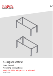
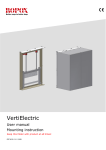
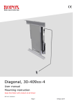
Smartbox, 30-69001-8
User Manual
Mounting Instructions
Keep always this folder with product!
PDF 5956 / 01.01.2011
Contents:
1.
INTRODUCTION ................................................................................................................................................. 2
2.
LIST OF COMPONENTS.................................................................................................................................... 3
3.
CONNECTION OF SMARTBOX ....................................................................................................................... 4
3.1
3.2
3.3
3.4
4.
Descriptions ................................................................................................................................................. 4
Connection of Smartbox to controlbox......................................................................................................... 5
Connection between Smartboxes.................................................................................................................. 5
Connection / naming of 8 Smartboxe in a system......................................................................................... 6
INITIALIZING THE SMARTBOX .................................................................................................................... 7
4.1
4.2
4.3
Numbering the Smartbox on the 8 polet DIP switch (Pos. 9): ..................................................................... 7
Indicate / Set first and last Smartbox in the system (Pos 10): ...................................................................... 7
Perform Master reset: .................................................................................................................................. 7
5
EXAMPLES........................................................................................................................................................... 8
6.
PERFORMANCE TEST ...................................................................................................................................... 9
6.1
7.
CLEANING AND MAINTENANCE ................................................................................................................ 10
7.1
8.
Performance test, electrically operated frame ............................................................................................. 9
Cleaning ..................................................................................................................................................... 10
TROUBLE SHOOTING..................................................................................................................................... 10
8.1
LED indications ......................................................................................................................................... 10
9
COMBINATION POSSIBILITIES & TRAPPING RISKS ............................................................................ 11
10.
CE-MARKING.................................................................................................................................................... 15
11.
COMPLAINTS .................................................................................................................................................... 16
1.
Introduction
If you want to avoid unnecessarily risk of trapping when installing several Ropox electrical height
adjustable frames in one system, you can do so, by using our Smartbox. The intelligent antitrapping system can be used when you have more electrical frames mounted next to each.
In these situations the Smartbox system will remove / eliminate the extra risk of trapping which is
not covered by the standard Safety strips and safty stopplates.
Up to 4 FlexiElectric can be connected side by side with the use of the Smartbox. Above this you
can also connect up to 4 VertiElectric side by side. This means that you can connect a maximum of
8 Smartboxes in one system. To see your combination possibilities, please refer to section 9.
Smartboxes must only be used together with Ropox products, such as FlexiElectric, VertiElectric
or 4SingleElectric, and only when mounting and daily use are according to this manual, and the
relevant manuals for FlexiElectric, VertiElectric or 4SingleElectric. The Smartbox will only be used
if you have two or more units mounted close together, and in this situations you need one
Smartbox per Controlbox in the system.
This document must ALWAYS be kept with the product and have been read and understood
by the user
The correct use, operation and inspection are decisive factors for efficient and safe performance.
Prior to assembly check that all parts have been provided. See list of components page 3.
Side 2
2.
List of components
Smartbox 30-69001-8:
The smartbox comprise:
1. Smartbox 98002100:
1 pc.
(1)
2. Extension cable 98002104:
L=3,5 cm male/male plug
1 pc.
(2)
(Pos. 2 to safety strip)
3. Communication cable 98002105:
L=250 cm male/male plug
1 pc.
(3)
(Pos. 3 to previous smartbox)
1 pc.
4. Communication cable 98002106:
L=50 cm modular cord
(4)
(Pos. 4 to controlbox)
5. Communication cable 98002107:
L=50 cm Din 7Polet plug
1 pc.
(5)
(Pos. 5 to controlbox)
6. Extension cable 98002008:
L=250 cm male/female plug
1 pc.
(6)
(Pos. 6 to next smartbox Pos. 3)
11. Spiral extension cable 98002016:
L =25-100 cm (black) to safety strip
1 pc.
(Between Pos. 6 & 3 at the smartboxes)
1 set
Common parts:
96000155 Adhesive pads
5 pcs.
Cable tidy strips
10 pcs.
The equipment should always be assembled by competent personnel
Side 3
(11)
3.
Connection of Smartbox
3.1
Descriptions
6. Connection to next Smartbox (Comm. Out)
10. Dip switch (indicates first and last Smartbox connected)
3. Communication input from previous Smartbox (Comm. In)
9. Dip switch for Smartbox settings (naming the Smartbox)
8. Led, light (to be used at power up and trouble
shooting)
2. Connection of Safety strip
4. Connection to Controlbox, modular plug
(Controlbox pinch input)
5. Connection to controlbox, Din plug (To controlbox handset)
7. Connection of the control switch for the table
12. Connection of the control switch for the VertiElectric (optional)
Pos. 3 is not being used on the first Smartbox in the system.
Pos. 6 is not being used on the last Smartbox in the system.
Side 4
3.2
Connection of Smartbox to controlbox
Motor connections
Safetystrip connection
Antipinch connection
to Smartbox
Din plug (To controlbox
handset)
VertiElectric
Table
3.3
Connection between Smartboxes
From Smartbox (Com.
out) to Smartbox (Com.
In)
Not in use if this is the
first Smartbox in the
system
From Smartbox (Com. out)
to Smartbox (Com. In)
Use cables (pos. 6 +11+3) Part No.
98002008 + 98002016 + 98002105
Side 5
From Smartbox (Com.
out) to Smartbox
(Com. In)
Not in use if this is the
last Smartbox in the
system
3.4
Connection / naming of 8 Smartboxe in a system
VertiElectric:
Last Smartbox =ON
Smartbox No. 2
VertiElectric:
Smartbox =OFF
Smartbox No. 4
2
1
ON
FlexiElectric:
First Smartbox =ON
Smartbox No. 1
VertiElectric:
Smartbox =OFF
Smartbox No. 6
4
VertiElectric:
Smartbox =OFF
Smartbox No. 8
6
3=Master
5
8
7
OFF
FlexiElectric:
Smartbox =OFF
Smartbox No. 3
FlexiElectric:
Smartbox =OFF
Smartbox No. 5
Side 6
FlexiElectric:
Smartbox =OFF
Smartbox No. 7
4.
Initializing the Smartbox
Up to 4 FlexiElectric can be connected side by side by the use of the Smartbox. Above this you
can also connect up to 4 VertiElectric side by side. This means that you can connect a maximum of
8 Smartboxes in one system. To see your combination possibilities, please refer to page 9.
All Smartboxes are given a unique number!
FlexiElectric: Can only achieve uneven numbers as 1, 3, 5, og 7.
VertiElectric: Can only achieve even numbers as 2, 4, 6, og 8
Smartbox No. 3 is ALWAYS master, and must ALWAYS be a part of your system.
4.1
Numbering the Smartbox on the 8 polet DIP switch (Pos. 9):
Set the dipswitch with the number of the unit FlexiElectric or VertiElectric, this example is for
FlexiElectric No. 3, which also are the master box
See also schematics
page 8
4.2
Indicate / Set first and last Smartbox in the system (Pos 10):
You need to tell the system how many Smartboxes you have in the system. You have to indicate /
set the first and the last Smartbox in the system. Use the DIP switch (pos 10) by setting No. 1 in
ON position, both on the first and also on the last Smartbox . All other Smartboxes in the system
has to be OFF.
See also schematics
page 8
(No. 2 is not in use).
ON
4.3
OFF
Perform Master reset:
Connect main power to all the controlboxes in the system.
Perform a reset of the master Smartbox (No. 3) - Deactivate the master by setting DIP switch (Pos.
9) to OFF. Activate again by setting it back to ON.
When you make this reset, the master will count the numbers of Smartboxes connected in the
system, and the LED (Pos 8) will flash the numbers.
After this procedure, the LED will turn off and work as normal
By activating the Safety strip, the LED will light up
Make a performance test according to section 6.
Side 7
5
Examples
See more combinations page 12
Last Smartbox =ON
Smartbox No. 4
4.
Last Smartbox =ON
Smartbox No. 2
5.
4
First Smartbox =ON
Smartbox No. 3 = Master
12.
Smartbox =OFF
Smartbox No. 4
2
1
First Smartbox =ON
Smartbox No. 1
2
4
3
3
Last Smartbox =ON
Smartbox No. 2
Smartbox =OFF
Smartbox No. 4
4
Frst Smartbox =ON
Smartbox No. 3 = Master
Smartbox =OFF
Smartbox No. 6
6
3
Smartbox =OFF
Smartbox No. 3 = Master
Side 8
6.
Performance test
6.1
Performance test, electrically operated frame
After installation and prior to use, all anti pinch functions of FlexiElectric and VertiElectric must be
tested. The test must be carried out by competent personnel. Subsequently the test shall be
carried out at least once a year:
Testing prior to connection of mains voltage:
1. Check that the mounting instructions have been observed.
2. Check that all cables have been connected correctly and that the plugs have been pressed
home.
3. Check that there are no load on the FlexiElectric or VertiElectric frames.
4. Check that there is nothing preventing the FlexiElectric or VertiElectric from moving freely
within the height adjustment range.
Now connect mains voltage to the control unit and proceed as follows:
5. Check that LED on master Smartbox (No. 3) flashes with the number of connected
Smartboxes.
For every FlexiElectric the following tests must be carried out:
6.
7.
Press DOWN on the control switch, move the FlexiElectric frame to bottom position and
check that the movement is even and smooth.
Press UP on the control switch, move the FlexiElectric frame to top position and check that
the movement is even and smooth.
Test of the safety between the FlexiElectric frames:
8.
Safety strip (downwards movement) on every FlexiElectric must be tested – See also
instructions in the FlexiElectric Manual
9. Move the first FlexiElectric to the top position, and the next FlexiElectric to the bottom
position
10. Press UP on the control switch (next FlexiElectric) and let the frame move 2-5 cm upward.
Now activate the safety strip on the first FlexiElectric by pressing it lightly. The frame must
stop the upward movement, move 1-2 cm downward and stop.
11. Test the rest of the FlexiElectric frames according to these procedures to make sure that all
risk of trapping has been tested and found safe.
Test of the safety between the FlexiElectric frames and the above VertiElectric:
12. First perform a performance test according to the VertiElectric Manual on each unit
13. Test one FlexiElectric at a time by moving it upwards, pressing the safety stopplate on the
above VertiElectric shall stop the upward movement, move 1-2 cm downward and stop.
14. Follow the above instructions to make sure that all combinations / trapping risk has been
passed (refer to combination possibilities section 9)
If all these tests are ok, the system of frames are ready for use.
Side 9
7.
Cleaning and Maintenance
7.1
Cleaning
The frame must not be connected to the mains voltage during cleaning.
Do not flush electrical components with water.
Smartbox must only be cleaned with a soft dry cloth
8.
Trouble shooting
8.1
LED indications
Master
X
X
X
X
X
X
X
Slave
X
X
X
X
LED
No light
Steady light
1 Flash
2 Flashes
3 Flashes
4 Flashes
2-8 Flash
Communication error:
Awaiting feedback:
Faulty DIP switch settings:
Number of Smartboxes variates:
Description
Everything is ok
Safety strip activated, or fault on safety strip on this
Smartbox
Communication error
Awaiting feedback from other smartboxes
Faulty DIP switch settings
Numbers of Smartboxes variates from original
Indicates the number of connected Smartboxes at power
up, or when master (Flexi 3 DIP switch (Pos. 10)
switches from OFF to ON.
Stopping all movements on master.
Stopping all movements on this Smartbox
Stopping all movements on this Smartbox
Stopping all UP movements on all Smartboxes (downward
is ok if the Safety strips is ok)
Side 10
9
Combination possibilities & trapping risks
When you have a combination of Ropox electrical frames, you can remove all trapping risk by
using the Ropox Smartbox.
On top of using the standard Safety strip and safetystopplates, this shows where the trapping risk
will occur when putting up a system like this. By using the Smartbox you will solve this, and make
your system even safer to use.
IMPORTANT : It is very important that the layout is according to this schematic, and that
the Smartbox has been installed according to this manual, and the manuals for FlexiElectric
and VertiElectric has been followed.
Arrows shows the extra risk of trapping that are covered by using this Smartbox. Ex.
FlexiElectric No. 3 will stop upwards movement if safetystopplate on Verti No. 2,4 & 6 are
activated, or the Safety strip on Flexi No. 1 & 5 are activated.
2
4
6
8
1
3=Master
5
7
Wallunit mounted on a VertiElectric, ALWAYS even No.:
4
Worktop mounted on a FlexiElectric, ALWAYS uneven No.:
3
1.
2.
1
3
3
5
1
5
3
3.
1
4.
4
7
5.
2
4
3
3
Side 11
6.
2
4
6
3
7.
8.
4
4
3
1
5
3
9.
10.
4
4
6
11.
12.
2
2
6
4
6
4
3
1
5
3
3
1
5
3
6
13.
4
6
3
5
14.
15.
4
6
3
8
2
5
1
4
6
3
16.
4
2
8
6
3
5
17.
18.
2
4
3
6
8
2
5
1
Side 12
4
6
3
8
19.
20.
4
1
6
4
3
5
4
6
1
3
5
21.
2
3
1
5
22.
23.
4
6
3
5
6
3
5
1
7
24.
25.
4
6
3
4
8
5
1
7
26.
6
8
3
5
27.
4
2
6
3
4
5
7
28.
1
3
8
6
5
29.
2
4
3
6
8
2
2
4
5
7
1
3
30.
6
8
5
31.
2
4
6
2
3
8
4
6
5
4
2
5
3
32.
4
1
7
8
7
Side 13
3
8
6
5
33.
34.
2
4
6
8
2
5
3
7
8
6
5
3
1
35.
4
36.
2
6
4
5
3
38.
2
4
6
8
1
3
5
7
1
3
5
3
7
5
40.
2
7
5
8
4
1
8
4
6
3
1
7
37.
39.
4
2
8
4
3
1
41.
5
7
42.
4
2
1
6
3
2
8
1
7
5
43.
6
3
8
1
5
44.
1
2
4
3
5
6
8
2
7
4
1
45.
8
6
5
3
7
46.
4
2
6
4
5
3
1
7
47.
2
1
4
3
6
5
8
7
Side 14
1
3
5
6
7
8
10.
CE-Marking
I hereby declare under sole responsibility that the following product:
30-69001
Smartbox
conform to the following directives and standards:
DIRECTIVES
·
73/23EEC, Low voltage directive
·
89/336/EEC, EMC-Directive
STANDARDS
DS/EN 60335-1 : 2002
DS/EN 61000-6-1: 2001
DS/EN 61000-6-3: 2001
Side 15
11.
Complaints
We refer to our general Terms of sale and delivery on our homepage www.ropox.com
ROPOX A/S
Ringstedgade 221
DK – 4700 Naestved
Tel.: +45 55 75 05 00 Fax.: +45 55 75 05 50
E-mail: [email protected]
www.ropox.com
Side 16