1
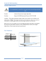
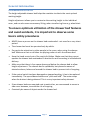
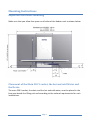
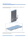
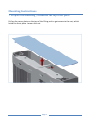
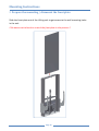
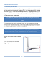
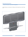
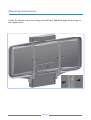
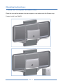
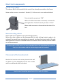
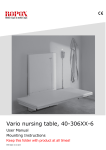
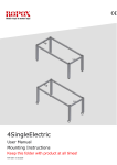
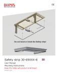
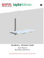
Hudson, shower bed
User Manual
Mounting instruction
Keep this folder with the product at all times
Content
Content.................................................................................................................................................. 2
Product information ............................................................................................................................................... 3
Part Numbers ......................................................................................................................................................... 3
Technical data ........................................................................................................................................................ 4
Daily use ................................................................................................................................................................. 4
The slat................................................................................................................................................................... 4
After use................................................................................................................................................................. 5
Recommendations in use ....................................................................................................................................... 6
Important info before mounting ............................................................................................................................ 7
Placement of the Main 230 V socket, the hot and cold Water and the Drain: ......................................................... 7
Mounting Instructions ............................................................................................................................................ 8
Receiving the Hudson Shower Bed: ........................................................................................................................ 8
1. Prepare the mounting / dismount the top cover plate ....................................................................................... 9
2. Prepare the mounting / dismount the front plate .............................................................................................10
3. Mounting to the wall .........................................................................................................................................11
4. Remount the front plate ....................................................................................................................................13
5. Mount the shelves on the Lifting unit. ...............................................................................................................14
6. Mount the Shower tray on the Lifting unit. .......................................................................................................15
Wire diagram ........................................................................................................................................................19
Connecting cables..................................................................................................................................................20
Disconnecting cables .............................................................................................................................................20
Placement of the handcontrol. ..............................................................................................................................20
Labelling .............................................................................................................................................. 21
Label......................................................................................................................................................................21
Symbol view: .........................................................................................................................................................21
Support................................................................................................................................................ 22
Fault finding ..........................................................................................................................................................22
Waste handling .....................................................................................................................................................22
Factors affecting the operation .............................................................................................................................22
Factors affecting storage and transport .................................................................................................................22
Spareparts ........................................................................................................................................... 23
Accessories .......................................................................................................................................... 24
Bed guard ..............................................................................................................................................................24
Maintenance ....................................................................................................................................... 25
Cleaning ................................................................................................................................................................25
CE- erklæring ....................................................................................................................................... 26
EU – Declaration of Conformity .............................................................................................................................26
Complaints........................................................................................................................................... 27
Page 2
General information
Product information
It is important to read this manual before mounting and daily
use.
Product
:
Hudson Shower bed, height adjustable
Producer :
Ropox, DK-4700 Naestved, Phone +45 55 75 05 00
Usability – The height adjustable shower bed can be used to nurse children and
adults (up to 150Kg). The shower bed can be used at home, in day care center or
institutions to obtain good and correct working conditions for the carer.
When not in use, the shower tray can be folded up against the wall to save space.
By using the up and down button on the handheld control switch, the height
adjustment of the shower bed can be performed.
Part Numbers
Length of
shower bed
146cm
178cm
210cm
Part No.
40-25023
40-25026
40-25029
Page 3
General information
Technical data
Electrical connection:
Standby consumption:
Duty cycle:
Height:
Material – Frame:
Shower tray:
Surface treatment:
Maximum load:
230V, 50Hz, max 2.0A
7W
Max 10%, 2 min/18 min
Work surface 30 – 100 cm
Unit, B=60 cm, H=116cm, D=13cm
Welded steel tubes St.37, Stainless and aluminum
ABS
Powder coating, white RAL 9010 matt, Chromate
150 kg
This product has CE-marking according to ”Medical equipment, Low
Voltage and EMC directives. Has been tested according to the European
standards DS/EN ISO 12182 and DS/EN ISO 60601-1. This product is in risk
group 1.
Daily use
Before start using this product, be sure that “main power” has been connected as
described in electrical connections.
By using the up ▲ down ▼ bottom on the handheld control switch, the height
adjustment of the shower bed can be performed. The control switch has a spiral
cord, which can be pulled out to a length of 200cm.
Maximum load onto the Hudson Shower bed 150 kg.
The slat
The slats have two sides with
different hardness and can be turned
around in the Shower tray.
The soft side is used, when the
person on the Shower bed needs to
be washed.
The hard side is used, when the
person on the Shower bed needs to
be changed.
Page 4
General information
After use
When not using the shower bed, the shower tray can be folded up against the Lifting
unit. This way it will only take up the space of approx. 30cm from the wall.
Inside the lifting unit, a gas damper is mounted, to reduce the power needed, when
folding the tray up and down.
Page 5
General information
Recommendations in use
The height adjustable shower bed helps the caretaker to obtain the most optimal
working height.
Height adjustment allows you to customize the working height to the individual
carer, and can also save unnecessary lifting, when transferring from e.g. wheelchair.
To ensure optimum utilization of the shower bed features
and avoid accidents, it is important to observe some
basics safety procedures
•
NEVER leave a person on the shower bed unattended - not even for a very short
period.
•
The shower bed must be operated only by adults.
•
Pay particular attention to other people in the room, when using the shower
bed. Make sure that no children are playing under or with the shower bed.
•
Keep the hand control out of the reach of children. Make sure that they cannot
operate the shower bed unattended. A bracket for wall mounting is included with
delivery.
•
Make sure that there is free space above and below the shower bed to allow
height adjustment. The shower bed is upfoldable, but please be aware of
obstacles above, below and around the shower bed to prevent risk of trapping.
•
If the control switch has been damaged or stopped working, it has to be replaced
immediately. The up and down buttons are “push and hold”. The motor stops
when the button is being released. This is a very important safety element.
•
If two shower beds are mounted next to each other, we recommend to mount a
side cover between, to avoid the risk of trapping.
•
Constantly be aware of objects under the shower bed.
Page 6
Mounting Instructions
Important info before mounting
Make sure that you allow free space on all sides of the Hudson unit as shown below.
Placement of the Main 230 V socket, the hot and cold Water and
the Drain:
The main 230 V socket, the drain and the hot and cold water, must be placed in the
free area beside the lifting unit and according to the national requirements for such
installations.
Page 7
Mounting Instructions
Receiving the Hudson Shower Bed:
The Hudson Shower Bed will come in two packages. One for the “Lifting unit” and
one for the “Shower tray unit”.
Lifting unit
Shower tray
It is important to follow the mounting instructions to assemble the unit in the right
way and to obtain a safe product.
Page 8
Mounting Instructions
1. Prepare the mounting / dismount the top cover plate
Pull up the cover plate on the top of the lifting unit to get access to the nut, which
holds the front plate. Loosen this nut.
Page 9
Mounting Instructions
2. Prepare the mounting / dismount the front plate
Slide the front plate out of the Lifting unit to get access to the wall mounting holes
in the unit.
!! Be aware not to bend or scratch the front plate in the process !!
Page 10
Mounting Instructions
3. Mounting to the wall
Attach the frame securely to the wall by using adequate bolts and rawlplugs suitable
for the type of wall construction / material on site. The Shower bed is being supplied
with a set (8 pcs) of screws and rawlplugs, which is ONLY used to mount the unit in a
concrete wall. If the unit must be mounted on another kind of wall, other kinds of
plugs and screws must be used. Shower bed is tested according to a load of up to
150 kg. applied to the shower bed.
If you have other objects mounted right next to this shower bed, you have to
consider the risk of trapping, and therefore consider a safe distance to the other
objects.
The attachment holes can be marked up on the wall, four possibilities in the top,
and four in the bottom of the frame. Place the frame against the wall and make sure
it is horizontal. The frame is standing on two adjustable feet. The holes in the frame
are all Ø 10 mm. Remove the frame and drill the holes.
Make sure that no dust or other obstacles are interfering with the rollers, chain,
sprocket or gas springs. This can cause malfunction and damage the system
Force for each of the four screws in top of the
unit:
Fscrew = (150 kg * 923)/(1122 * 4 screws)
Fscrew = 31 kg for each screw
Page 11
Mounting Instructions
Page 12
Mounting Instructions
4. Remount the front plate
Slide the front plate back into the Lifting unit and fasten it with the nut.
Page 13
Mounting Instructions
5. Mount the shelves on the Lifting unit.
Use 4 pcs. M5x10 screws to mount the shelves on both sides of the lifting unit.
Page 14
Mounting Instructions
6. Mount the Shower tray on the Lifting unit.
Slide the Shower tray in between the Lifting unit and the support arms on the Lifting
unit.
Page 15
Mounting Instructions
Fasten the Shower tray to the Lifting unit with 8 pcs. M8x16 through the bushings in
the support arms.
Page 16
Mounting Instructions
7. Mount the cover plate on Shower tray
Place the cover plate between the two support arms underneath the Shower tray.
Fasten it with 4 pcs M5x10
Page 17
Mounting Instructions
8. Mount the Drain and Flexible hose on the Shower tray
Screw the plastic nut on the scuttle and tighteen it firmly. Connect the flexible hose
to the drain tube and connect it to the drain in the wall or on the floor.
•
•
•
After mounting, make sure that the chain is in correct position on the sprocket,
also check that cable plugs is connected correctly to the control box.
Check that no cables can be trapped or squeezed
Connect the main power, and the shower bed is ready to be used.
Page 18
Electrical components
Wire diagram
The shower bed is delivered with the control box already mounted on the frame.
The diagram shows how the cables which are connected to the control box.
All the plugs are water tight, and therefore
they can be a little tricky to connect /
disconnect. Make sure that the plugs are
positioned correctly before they are pushed
into the sockets at the control box. The plugs
must be pushed into the sockets until the “Oring” is no longer visible.
Motor, control box and control switch apply to
IP66. This means that they are dust tight and
protected against heavy seas, or powerful jets
of water.
The electronic system is designed for periodical
use only, this means a max. duty cycle of 10%;
2min on /18min off.
1
1.
2.
3.
4.
5.
Control box
Mains cable 230V
Motor, connects to socket 1
End plugs, connects to socket 2, 3 & 4
Hand control, connects to HB socket
2
5
4
3
Page 19
Electrical components
Connecting cables
The shower bed is delivered with the control box already mounted on the frame.
Motor cable connects to socket 1. Socket 2, 3 & 4 are not in use and are blocked.
Control switch connects to ”HB”.
When all cables have been connected, use the safe
locking bracket. Pushed in until you hear a “click”.
Mains cable connects to the socket at the side of the
box.
Disconnecting cables
Mains cable can be pulled out (no safe locking bracket).
Before the other cables can be disconnected, the safe locking bracket needs to be
released / removed (use a screwdriver to remove). Locking clips at each end of the safe
locking bracket have to be released before the bracket can be removed, and the cables
can be disconnected.
To obtain the full IP66 value, it is very important that all the plugs have been pressed
firmly into the sockets and the safe locking bracket is mounted.
Placement of the handcontrol.
Bracket for hand control can be placed at the wall
as shown. To be mounted with the two screws
which are delivered with the bracket.
Hand control should be placed out of the reach of children
Page 20
Labelling
Label
Each shower bed has its own label as shown. The label contains information which is
very important to specify when contacting your supplier. It also shows main power
supply.
Item No.
Serial No.
Name /
model
See explanation below
Production year &
month
Max. load 150kg
Symbol view:
User Manual must be read before use
Waste must be sorted. Most parts for re-use.
Type B equipment. As for EN 60601-1
Class 2 equipment. Without earth connection.
CE-marking. This product complies with the demands for general safety and
functionality in the relevant EU directives and standards.
i
EMC information
The shower bed complies with the demands for electromagnetic
compatibility (EMC), if installation and daily use is according to instructions
in this Manual.
In seldom situations the Shower bed might be affected by electronic signals
from ex. Portable computers, cell phones etc.
Page 21
Support
Fault finding
Hudson does not move up or
down by when operating
using the hand control
Hand control defect
By pressing the up or down
button, no movement is
achieved, only clicking sounds
is are heard from control box
Check if:
Main power connected 230V.
Motor is connected to control box
Hand control is connected to control box
Motor is overloaded
Check if:
Hudson works with another hand control
Plugs are not connected correctly.
Dismount all cables and re-connect.
Waste handling
Used equipment shall be disposed of according to the National law. We
recommend to dismount the product to the greatest extent possible, in a
way that most parts can be reused. Be aware that this product contains
electronically components. Example of groups this product can be sorted in:
metal, plastic, cables, electronics and parts for destruction.
Factors affecting the operation
i
Temperature:
0°C to 40°C
Relative humidity:
5% to 85% non-condensing
Factors affecting storage and transport
i
Page 22
Spareparts
Spareparts
97000431
Actuator/motor
Type : LA34.5
Stroke 350 mm
97000434
Control Box
Type : CB6096-2
97000425
Hand Control
Type : HB8195V0001+61
40*40090-180
Slat
40*40090-315
Flexible plumbing kit
Page 23
Accessories
Bed guard
Bed guard is available as an option. The brackets will be mounted underneath the
frame with the screws supplied.
Length of
Shower bed
Shower bed
Bed guard foldable
L=126 cm
Bed end guard
Fixed
146cm
40-25023
40-25036
40-25038
178cm
40-25026
40-25036
40-25038
210cm
40-25029
40-25036
40-25038
Page 24
Maintenance
The Hudson is maintenance free. For safety reasons it is recommendable to check all
mounting screws and moving parts to be sure all is tightened ok, and that all
attachment to the wall is in correct and safe condition.
Cleaning
To clean this product, do not use a high-pressure washer.
Simply use a soft cloth or sponge with soapy water (pH 7) of max 60°C or
householding spirit.
Always clean this product after use to prevent dirt from sticking to the surface.
Important:
Do not use scouring powder or other abrasives as they may scratch the surface. Also
avoid the use of cleaning utensils with sharp edges. Never use strong mineral acids
or alkali.
Page 25
CE- erklæring
EU – Declaration of Conformity
I hereby declare under sole responsibility that the following products:
40-25023 Hudson Shower bed, 146 cm
40-25026 Hudson Shower bed, 178 cm
40-25029 Hudson Shower bed, 210 cm
are all under Classification Class I and in conformity with the following directives and
standards:
DIRECTIVES
• The Council Directive No.2007/47/EEC, concerning Medical Devices
amended through Directive No.98/79/EC
• 2006/95/EEC Directive for Low-voltage, amended through Directive
No.93/68/EEC
• 2004/108/EEC, EMC-Directive, amended through Directives
No.92/31/EEC and 93/68/EEC
STANDARDS
DS/EN
DS/EN
DS/EN
DS/EN ISO
Dato:
1041:
14971:
12182:
9999:
2009
2008
2002
2009
DS/EN ISO
DS/EN
DS/EN
01-05-2011
Page 26
10993-1: 2009
60601-1+CORR: 2006
60601-1-2: 2007
Complaints
See General Terms of Sale and Delivery on www.ropox.com
Ropox A/S
Ringstedgade 221
DK – 4700 Næstved
Tel.: +45 55 75 05 00 Fax.: +45 55 78 05 50
E-mail: [email protected]
www.ropox.dk
Ropox A/S
Ringstedgade 221
DK – 4700 Naestved
Tel.: +45 55 75 05 00 Fax.: +45 55 78 05 50
E-mail: [email protected]
www.ropox.com
Ropox A/S
Ringstedgade 221
DK – 4700 Naestved
Tel.: +45 55 75 05 00 Fax.: +45 55 78 05 50
E-mail: [email protected]
www.ropox.de
Page 27