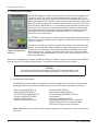
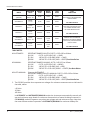
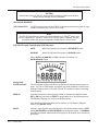
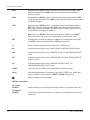
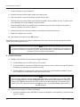
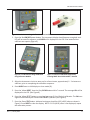
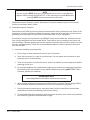
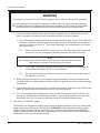
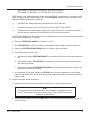
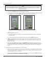
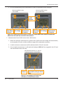
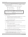
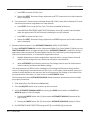
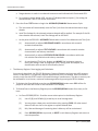
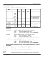
1
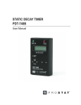
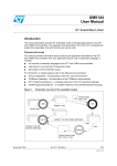
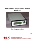
RESISTANCE METER
PRS-812
User Manual
Table of Contents
PROSTAT® PRS-812 RESITANCE METER
Section
Topic
Page
I.
Introduction & Description
4
II.
Cautions & Warnings
7
III.
Controls, Connections & Indicators
9
IV.
Battery Installation and Replacement
15
V.
Setup & Calibration
16
VI.
Instrument Operation
18
VII.
Instrument Maintenance
31
VIII.
Warranty Information
32
General Specifications
34
Instrument Controls
35
Copyright © 2012 by Prostat® Corporation. All rights reserved. Printed in the United States of America. No part of this
manual may be used or reproduced in any manner whatsoever without written permission. For information contact
Prostat Corporation, 1072 Tower Lane, Bensenville, IL 60106 USA
Prostat is the registered trademark of Prostat® Corporation
PRS-812 Resistance Meter
I. Introduction & Description
The PRS-812 Resistance Meter makes precision resistance measurements from
0.1 up to 1.0x10¹² ohms with an overall measurement tolerance of ±5%. It is
capable of measuring up to 2.0x10¹⁴ ohms with tolerance depending on procedures and conditions. The PRS-812’s wide range and close tolerance make it the
ideal ESD Auditing instrument for measuring resistance to a variety of ESD and
general industry specifications. It is operated by programmed microprocessors
that control the instrument’s measurement process, resistance auto ranging,
test voltage selection, electrification periods, and display functions. It can be
operated in either fully automatic or manual modes, or a combination of
automatic and manual modes.
The PRS-812 is unique in that it records and stores up to 80 resistance measurements in its own non-volatile memory register. Stored data is summarized with
a push of a button.
Figure 1: PRS-812 during
power up
Its accuracy is based on its ability to rapidly make several measurements each
second, and average them until a stable set of eight measurements, all within
5% tolerance, are obtained. The final averaged data is displayed as the resistance measurement. Typically, measurements at less than 1 ohm are within
5% of tolerance, and those between 1.0 and 1.0x10¹² ohms are within 0.5% of
laboratory references
While quite sophisticated in design, the PRS-812 Resistance Meter is easy to use and extremely helpful in
making accurate ESD auditing measurements, or general resistance and continuity checks.
CAUTION
To avoid electrical shock or damage to the PRS-812 Resistance Meter, read
this manual completely before installing batteries or using the instrument.
A. Measurement Applications
The PRS-812 Resistance Meter is designed to measure resistance characteristics of electrostatic
discharge (ESD) control materials and products to current ESD industry standards, including:
Wrist Straps (ANSI/ESD S1.1)
Flooring (ANSI/ESD STM7.1)
ESD CP Grounds (ANSI/ESD S6.1)
Footwear (ANSI/ESD STM9.1)
Equipment (ESD SP10.1)
Material Handling Containers
Garments (ESD STM2.1)
Worksurfaces (ANSI/ESD S4.1)
Carts & Seating (ANSI/ESD STM 12.1)
Workstations
Production Aids & Hand Tools
Packaging (ANSI/ESD STM11.11, ANSI/ESD
STM11.12 & ASTM 257), and Other ANSI/
S20.20 ESD Program Control Elements
Note: Additional fixtures and electrodes supplied separately are required for many of these measurement.
4
Rev. C / January 2012
PRS-812 Resistance Meter
B. PRS-812 Resistance Meter Components:
The PRS-812 Resistance Meter includes the following items:
1. PRS-812 Resistance Meter Instrument with 2 each 9V alkaline batteries.
IMPORTANT NOTE
Only use alkaline batteries for optimal performance.
2. Two 10-foot leads (PRS-800LB & PRS-800LR) for general audit measurements up to 1.0x10¹²
ohms.
3. One heavy duty, black “Bulldog” clip (PRS-801BC)
4. Two Metal Alligator Clips (PSI-870MAC)
5. One Audit Test Bed (PTB-915)
6. One calibration shunt for low range adjustment (PRS-801CC)
Optional accessories are available for the PRS-812 Resistance Meter. Visit www.prostatcorp.com
for additional information.
C. PRS-812 Basic Description & Functions
The PRS-812 Resistance Meter has several test, display and data logging functions:
1. The PRS-812 six basic measurement modes are described in the following table
Rev. C / January 2012
5
PRS-812 Resistance Meter
MODE
DISPLAYED
UNITS
INDICATION
RESIST.
RANGE
TEST
VOLTS
AUTOMATIC 1
[Default]
1.0EXX
IND Ω - TΩ
AUTO
AUTO.
AUTO.
AUTOMATIC 2
OHMS
Ω - TΩ
AUTO
AUTO.
AUTO.
MANUAL 1
1.0EXX
IND Ω - TΩ
MANUAL
MAN
MAN. or
AUTO
MANUAL 2
OHMS
Ω - TΩ
MANUAL
MAN
MAN. or
AUTO
MANUAL/
AUTOMATIC 1
1.0EXX
IND Ω - TΩ
AUTO &
MANUAL
MAN. Start
AUTO
Run
AUTO.
MANUAL/
AUTOMATIC 2
OHMS
Ω - TΩ
AUTO &
MANUAL
MAN. Start
AUTO
Run
AUTO.
TEST
FUNCTIONS
AUTOMATIC RESISTANCE RANGE,
TEST VOLTS, ELECTRIFICATION,
DISPLAY HOLD
SEE TABLE NOTE #1
TEST ONLY; NO DISPLAY HOLD
UL= UNDER DECADE LEVEL
OL= OVER DECADE LEVEL
SEE TABLE NOTE #2
MANUAL SETUP STARTING
DECADE, AUTO ADJUST RANGE,
TEST VOLTS, ELECTRIFICATION
DISPLAY HOLD
SEE TABLE NOTE #3
TABLE NOTES:
#1 AUTOMATIC:
RESISTANCE RANGES IN AUTO 0.1Ω TO <2.0E+12Ω as follows
@<10V:
0.1 TO <1.0E+04Ω (0.1Ω - < 10KΩ)
@ 10V: 1.0E+04 TO <1.0E+06Ω (10KΩ - < 1MΩ)
@100V: 1.0E+06 TO <2.0E+12Ω (1MΩ - <200TΩ) See Note Below
#2 MANUAL: RESISTANCE RANGES IN MAN 0.1Ω TO <2.0E+12Ω as follows
@<10V:
0.1 TO <1.0E+05Ω (0.1Ω - <100KΩ)
@ 10V: 1.0E+03 TO <1.0E+09Ω (1KΩ - <1GΩ)
@100V: 2.0E+05 TO <2.0E+12Ω (200KΩ - < 200TΩ) See Note Below
#3 AUTO-MANUAL:
(Same as AUTOMATIC)
RESISTANCE RANGES IN AUTO-MANUAL 0.1Ω TO <2.0E+12Ω as follows
@<10V: 0.1 TO <1.0E+04Ω (0.1Ω - < 10KΩ)
@ 10V: 1.0E+04 TO <1.0E+06Ω (10KΩ - < 1MΩ)
@100V: 1.0E+06 TO <2.0E+12Ω (1MΩ - <200TΩ) See Note Below
2. The PRS-812 provides three separate test voltages for resistance measurements as indicated in
the table, above:
<10 Volts
10 Volts
100 Volts
In AUTOMATIC and AUTOMATIC/MANUAL modes the instrument automatically controls voltage and resistance range based on resistance characteristics of materials being measured. In
the MANUAL mode the operator may select test voltage and and resistance range. Note that
the most efficient mode of operation in AUTOMATIC/MANUAL for maximum battery life.
6
Rev. C / January 2012
PRS-812 Resistance Meter
3. The PRS-812 displays resistance Measurements in several ways:
a. 14 factory programmable LED’s each representing one order of magnitude from <103 to
>1012 ohms. LED’s have three colors, including:
GREEN
RED
YELLOW/ORANGE
NOTE
The PRS-812 provides very accurate measurements up to 1.0x10¹² ohms, and
has the capability to display values up to 2.0x10¹⁴ ohms. However, the user
should be aware that accuracy degrades rapidly above 1.0x10¹² ohms.
b. The large Liquid Crystal Display (LCD) includes an analog (1 - 10) scale and X1, X10 and X100
multiplier indication for measurement in Ω, KΩ, MΩ, GΩ and TΩ.
c. Digital measurements are provided using integers and Ω, KΩ, MΩ, GΩ, TΩ indicators, or in
exponential format (1.0EXX) with Ω -TΩ indicators.
4. The PRS-812 includes data logging (storage) capabilities for up to 80 data points when RECORD
is selected. The instrument will provide access to the memory register, calculate and display
Minimum, Maximum and Average of all measurements in the instrument’s memory whenever
RECALL is selected.
II. Cautions & Warnings
As with any electrical device, use proper safety precautions and safe measurement procedures to
avoid personnel shock and arc discharge.
A. The PRS-812 Resistance Meter is battery operated and delivers test voltages up to 100 volts.
IMPORTANT: Only use alkaline batteries in the PRS-812.
B. The instrument is current limited for safety, however, if improperly used it may be capable of delivering an annoying shock to a person touching conductors energized by the PRS-812, particularly at
100 volts.
C. While current limited, a hazard exists in personnel reaction to a potential shock.
D. To avoid personnel shock, follow the General Operations instructions at all times. Do not touch
energized electrodes or fixtures when power is applied except as specifically described in this and
accessory instructions.
E. Do not operate or store the instrument in damp environments or wet conditions.
Rev. C / January 2012
7
PRS-812 Resistance Meter
CAUTION
Storage or use of this instrument in high humidity, damp or wet conditions
may cause damage to the instrument’s electronic circuits, effect performance
and can increase the possibility of personnel shock or arc discharge.
F. Do not use the PRS-812 in combustible or explosive environments
WARNING
Improper handling and use of energized circuits may cause arc discharge,
which in turn may cause the ignition of combustible materials or fumes.
Do not use exposed energized circuits in flammable areas.
G. Do not attempt to measure energized circuits with the PRS-812
H. Do not use the PRS-812 if it becomes damaged in any way
I. Only Prostat trained instrument personnel should attempt to service or repair the PRS-812
J. Other Safety & Operating Considerations
1. This manual displays cautions and warnings alerting the user to hazardous operation and servicing conditions. CAUTION or WARNING headings throughout this publication flag this information, where appropriate. Follow all caution and warning instructions at all times.
2. The PRS-812 is a precision instrument and should be operated by experienced personnel familiar with the use and handling of devices containing power supplies.
CAUTION
The PRS-812 Contains Electrostatic Discharge Sensitive (ESDS) components
and includes precision alignment of circuit elements. Only Prostat trained and
ESD Qualified instrument repair personnel should perform service.
3. The PRS-812 contains Electrostatic Discharge Sensitive (ESDS) components. Qualified personnel
should service it only at ESD Controlled workstations. Do not attempt to dismantle the PRS-812
8
Rev. C / January 2012
PRS-812 Resistance Meter
without Prostat’s authorization and expert supervision. The instrument contains exceptionally
clean circuits that are aligned and adjusted in a precise manner for optimal operation and accurate performance. Unauthorized opening of the PRS-812 housing will void the instrument’s
warranty.
WARNING
Unauthorized opening of the PRS-801 case or dismantling in any manner
WILL VOID THE INSTRUMENT’S WARRANTY.
4. Read this manual in its entirety before installing batteries or using the PRS-812.
5. Do not drop or cause unnecessary mechanical shock to your PRS-812 instrument.
6. Store the instrument in a clean, dry environment. Do not expose the instrument to wet, extremely hot or cold conditions.
7. If the unit is stored in a cold environment, allow it to stabilize at room temperature before
powering up the unit. This will prevent damage due to condensation that may accumulate on
the instrument’s circuit boards.
III. Controls, Connections & Indicators
Before operating the PRS-812 instrument become familiar with each control and display function. A
thorough understanding of the instrument’s operation will make its use a pleasant experience, enhance measurement accuracy, avoid mistakes and prolong the life of the instrument.
PRS-812 CONTROLS:
[1] FUNCTION/ MODE
Toggles Through Six Operation Modes
(1) AUTO: (AUTOMATIC) displays data in exponential format 1.0EXX
NOTE: AUTO in exponential format, e.g., 1.3E05, is the Default start up mode when the instrument is turned ON.
Rev. C / January 2012
(2) AUTO: (AUTOMATIC) displays data in Ω, KΩ, MΩ, GΩ and TΩ. The instru
ment controls resistance ranges, test voltage and electrification periods in AUTOMATIC mode.
9
PRS-812 Resistance Meter
Figure 2: PRS-812 Controls & Display Indicators
(3) MANUAL: displays data in exponential format 1.0EXX
(4) MANUAL: displays data in Ω, KΩ, MΩ, GΩ and TΩ
(5) AUTO-MANUAL: displays data in exponential format 1.0EXX
(6) AUTO-MANUAL: displays data in Ω, KΩ, MΩ, GΩ and TΩ
In MANUAL, the operator selects resistance range in single decade increments. Test voltage may be selected by the operator, or allowed to function automatically based on resistance range selected. The operator determines electrification period in seconds (SEC) using the displayed timer in the center of the LCD.
In AUTO-MANUAL the operator may select the initial resistance range in
decade increments. Once set, the PRS-812 starts the measurement process
from the preset resistance decade, rather than re-zeroing itself for each
measurement. This feature saves measurement cycle time and extends
battery life. In this mode the instrument automatically controls test voltage,
range and measurement electrification period.
10
Rev. C / January 2012
PRS-812 Resistance Meter
[2] RESISTANCE RANGE
SELECTION
[3] TEST VOLTS
Two Triangular Arrows Buttons, UP (↑) and DOWN (↓), select Resistance Measurement Range in single orders of magnitude while in MANUAL or AUTOMATIC/MANUAL modes
Manual Selection of <10, 10 or 100 volts in MANUAL selects initial test
voltage. MANUAL Test Voltage & Resistance Limits are as follows:
@<10V:
@ 10V: @100V: [4] RECORD/RECALL
0.1 to <1.0E+05Ω (0.1Ω - <100KΩ)
1.0E+03 to <1.0E+09Ω (1KΩ - <1GΩ)
2.0E+05 to <2.0E+14Ω (200KΩ - <200TΩ)
NOTE: Optimal minium measurement in MANUAL using 100 volts is 2.0E+05.
If REC is not displayed in the lower left corner of the LCD, pressing RECORD/
RECALL once turns Memory Register ON [REC will then be displayed in LCD]. If REC is ON and measurement data is stored in memory, pressing RECORD/RECALL once will provide access to the memory register. Pressing RECORD/RECALL successively will calculate and sequentially display
Minimum [MIN], Maximum [MAX] and Average [AVG] of data stored in the Memory Register. If memory is ON and register contains stored data pressing RECALL will provide the following information:
First Press RECALL:
NOTE: MEM XX Flashes in LCD indicating number of data points in the register and the last measurement is displayed. Pressing DOWN (↓) and UP (↑) displays other data points and their respective position in the register is shown in the MEM XX section of the LCD.
Second Press RECALL:
Provides access to data in Memory
Displays MIN Data Point in Memory
Third Press RECALL:
Displays MAX Data Point in Memory
NOTE: When displayed, OL [Over Level] indicates a measurement greater than (>) 2.0x10¹⁴ ohms, which is beyond the measurement capability of the PRS-812.
Fourth Press RECALL:
Displays AVG of all Memory Data Points
NOTE: OL [Over Level] measurements [>2.0x10¹⁴ ohms] are not included in displayed average (AVG) calculation.
Fifth Press RECALL:
Returns System to normal operations
NOTE: If in RECALL mode, pressing RESET will return the instrument to normal
measurement operations.
Rev. C / January 2012
11
PRS-812 Resistance Meter
NOTE
If RECALL is not pressed, a fifth time OOPS will be displayed in the
LCD when TEST is next pressed. To Clear OOPS, press RESET. The instrument will
return to normal operations.
[5] CLEAR
In normal operations CLEAR erases data in Memory Register, discards most recent measurement, or turns the REC function OFF as follows:
a. When in any operation mode, and HOLD is not displayed, pressing
CLEAR will erase all data stored in Memory.
NOTE
The process of turning the REC function OFF will clear the Memory
Register of all stored data. Be sure that this is indeed desirable before
pressing the CLEAR button.
b. If a measurement is displayed in HOLD, prior to pressing RESET buton
pushing CLEAR will discard that held value and will not enter it into
Memory. Other data in Memory Register remains intact.
c. If reviewing data in the Memory Register while in the RECALL mode,
pressing CLEAR will discard the displayed data point. Other data in
Memory Register remains intact and indexes down one space to replace
the discarded data point.
d. When in any operation mode, and HOLD is not displayed, pressing
CLEAR will erase all data stored in the Memory Register. Pressing OFF
will disble the REC mode and the instrument will be de-energized. When
powered up again the REC mode will remain disabled until RECORD/RECALL is pressed once.
12
[6] ON/OFF Turns instrument ON for normal operations, performs functional & Battery tests, turns instrument OFF.
[7] BATT. TEST
Displays GOOD on LCD if battery provides acceptable voltage for accurate measurements, or displays Lo if unacceptable and batteries require replace
ment.
[8] RESET
Saves measurement and prepares instrument for next test cycle, i.e., enters measurement into Memory Register if REC is ON, and clears HOLD and the LCD display between measurements.
[9] TEST
Begins measurement sequence in accordance with selected mode
[10] BATTERY
BUSS CUT OFF
Battery buss cut-off switch is used to isolate the main batteries from the instrument’s circuit during battery change, instrument storage and transport.
Rev. C / January 2012
PRS-812 Resistance Meter
CAUTION
Switch battery buss to the OFF position before changing batteries to avoid reverse polarity damage to the instrument.
LCD DISPLAY ELEMENTS
[11] Colored LED’s
14 LED’s across the top of the PRS-812 indicate measurement order of mag-
nitude in decades from <103 to >1012 ohms.
NOTE
The PRS-812 provides very accurate measurements up to 1.0x10¹² ohms, and
has the capability to “indicate” values up to 2.0x10¹⁴ ohms. However, the user
should be aware that accuracy degrades rapidly above 1.0x10¹² ohms.
[12] PRS-812 Liquid Crystal Display (LCD) Elements:
AUTO
When ON Indicates instrument in AUTOMATIC mode
MANUAL
When ON indicates instrument in MANUAL mode
When AUTO and MANUAL are ON, indicates instrument is in
AUTO-MANUAL mode.
Analog Scale
& X100 Indicator
The one decade analog scale elements darken to indicate measurement in
teger. X1, X10 or X100 darken to indicate the scale multiplier. Combine the Analog indicators with Ω, KΩ, MΩ, GΩ and TΩ symbols to obtain an analog measurement.
MEM 00
Provides the number of data points stored in the Memory Register when REC is ON and instrument is RESET in preparation for a new measurement. The Memory Register can store up to 80 data points.
Also identifies a displayed data point’s position in the Memory Register when in the RECALL mode.
00 SEC
Display’s electrification period required for the measurement when in TEST during AUTOMATIC and AUTO-MANUAL measurement modes. In MANUAL, provides continuous measurement timing up to 99 seconds, then restarts at 0 seconds.
Rev. C / January 2012
13
PRS-812 Resistance Meter
MIN
Displayed when RECALL button is pushed second time while in REC mode. Number displayed when MIN is indicated is the Minimum data value in Memory Register.
MAX Displayed when RECALL button is pushed a third time (sequentially) in REC mode. Number displayed when MAX is indicated is the Maximum data value in Memory Register.
AVG
Displayed when RECALL button is pushed the fourth time (sequentially) in REC mode. Number displayed when AVG is indicated is the Average of all data values in Memory Register that are less than 2.0x10¹⁴ ohms. (OL’s are not included in averaging calculation.)
Note: Either the RECALL button must be depressed a fifth time or RESET pressed to return the system to its operational, measurement mode.
REC
Indicates that the Memory Register is ON and is Recording data each time the RESET button is depressed after a TEST measurement.
Ω
Ohms: Indicates measurement between 0.1 and 999 ohms
KΩ
Indicates measurements from 1,000 (1.0x10³) to 990,000 (9.9x10⁵) ohms
MΩ
Indicates measurements from 1,000,000 (1.0x10⁶) to 999,000,000 (9.9x10⁸) ohms
GΩ
Indicates measurements from 1,000,000,000 (1.0x10⁹) to 999,000,000,000 (9.9x10¹⁰) ohms
TΩ Indicates measurements from 1,000,000,000,000 (1.0x10¹²) to 200,000,000,000,000 (2.0x10¹⁴) ohms
<100 V
Indicates <10, 10 or 100 volts being applied as the test voltage.
HOLD
Indicates measurement is complete at the end of a TEST cycle. Holds data point in display until instrument is RESET or CLEAR is depressed.
Battery indication for low voltage
PRS-812 Connections
14
[+] Positive
Terminal
Power terminal for supplying Test Voltage to fixture or material under test.
[-] Negative
Terminal
Sensing Terminal for measurement of current (I) through fixture or material under test.
Rev. C / January 2012
PRS-812 Resistance Meter
Battery Compartment
Located in lower section of case, opposite LCD display. Holds two 9V-transistor batteries. Two
screws secure the battery cover. Note: Use only Long Life Alkaline Batteries. Remove batteries
when instrument is not in use for long periods of time.
Battery Buss Switch
MUST be off during
battery change.
Figure 3: Opening Battery Compartment
Figure 4: Install 2 each 9V Alkaine
Batteries
IV. Battery Installation (See Figures 3 & 4)
For optimal battery life and avoid instrument damage, always replace the batteries with high energy,
alkaline batteries. Failure to do so will result in a diminished battery life, measurement error and potential
instrument damage that could void the warranty.
The battery caps on the instruments you have purchased are designed to fit snugly. Please follow the directions below for safe replacement of batteries.
A. Slide battery bus switch to the OFF position (see figure 3).
B. Carefully remove the battery cover from the instrument.
C. Gently take the batteries from the battery compartment.
D. Unwind any battery lead that is wrapped around the top of the battery terminal. Do not pull battery connection leads - this could cause instrument damage.
E. Very carefully place a flat head screwdriver between the battery terminals and gently lift the battery cover from the battery.
Rev. C / January 2012
15
PRS-812 Resistance Meter
F. Properly dispose of any old batteries.
G. Position the new alkaline battery under the battery cover.
H. With your thumb, press the terminals in place one at a time.
I. Carefully wind any excess battery lead around the battery terminal below the cap. To avoid instrument damagae, do not pull battery connection leads
J. Place the batteries back into position with the battery terminal covers facing the lead spurce
within the battery case shown in figure 4.
K. Carefully position the instrument battery cover back into place without force.
L. Replace the battery cover screws.
M. Slide battery buss switch to the ON position.
Following the above directions for battery replacement will insure that you do not damage the battery
covers or wires during this process.
NOTE
It is recommended to measure the voltage of each battery with a multimeter. If the voltage of
one battery measures at or below 6.75 volts, replace that battery. If both batteries measure at
or below 6.75 volts, replace both batteries.
V. Setup & Calibration
A. Setting up the PRS-812 for low resistance range calibration
1. Position Battery Buss Cut Off switch to OFF position
2. To install batteries, remove two Phillips locking screws and cover. Attach two Long-Life, Alkaline
9V batteries to the battery connection terminals.
3. Position batteries in compartment with power leads neatly positioned above battery connections. Carefully re-install battery cover and locking screws.
NOTE
Do Not change batteries with the battery buss ON. Always switch Battery Buss Cut Off to OFF
when changing batteries. Should the ON/OFF button be depressed during battery change and
Battery Bus is ON the instrument may lock up and not function properly or be seriously damaged. In this case, simply disconnect the batteries, then re-install with Battery Buss switch in
the OFF position.
B. Low Resistance Range (<10 Ohms) Calibration
1. Install the calibration shunt (PRS-801CC) across the Negative (-) and Positive (+) Lead Terminals
(Figure 5, below).
16
Rev. C / January 2012
PRS-812 Resistance Meter
Figure 5: Low Resistance Range Calibration Shunt Installation
2. Press the Red ON/OFF power button. The instrument display should become energized, each
LED will be tested in sequence, and GOOD will is displayed in the LCD if the batteries have
sufficient test capacity (figure 9).
Figure 6: Low Resistance Range Calibration
using Reference Module
Figure 7: Start the Calibration Sequence by
Pressing RESET then CLEAR within ½ Second
3. Allow the instrument circuits to warm-up for a few minutes; approximately 2 - 3 minutes are
sufficient, prior to completing the calibration sequence.
4. Press MODE once to shift display to ohms mode (Ω).
5. Press the Yellow RESET, then the Gray CLEAR button within ½ second. The message CAL will be
displayed in the LCD. (See Figure 8)
6. Press the Yellow RESET button to complete low range (0.1 to 10 ohm) calibration. The CAL message will automatically be cleared when RESET is pressed. (See Figure 8)
7. Press the Green TEST button. Indicated resistance should be 1.02 (±0.02) ohms as shown in
Figure 8. Press RESET to clear the display. NOTE: If 1.02 (±0.02) ohms is not displayed, repeat
the calibration process.
Rev. C / January 2012
17
PRS-812 Resistance Meter
8. Remove the calibration shunt assembly from the lead terminals
9. The PRS-812 is now ready for wide range measurements from 0.1 to 1.0E+12 Ohms
Figure 8: Complete Calibration Sequence by Pressing RESET. To confirm Calibration,
Press TEST to measure the Calibration Shunt resistance. Shunt resistance should display
1.02 Ohms ±0.02 Ohms
VI. Instrument Operation
A. Overview of PRS-812 Operation & Measurement Test Cycle Sequence
The following 10 points provide a general overview for calibrating and using the PRS-812 for resistance measurements.
1. Slide Battery Buss Cut Off switch to ON
2. Press Red ON/OFF button once to power up PRS-812
a. Instrument performs circuit check, and tests LED’s, LCD display, and battery voltage.
b. LCD displays GOOD if battery voltage suitable for instrument operation; displays Lo if batteries require replacement
c. Instrument ends startup sequence in default AUTO, Exponent Display Mode 1.0EXX
3. Select Function Mode if other than AUTO, Exponent Display Mode 1.0EXX is desired by pressing MODE button
4. Perform low resistance range calibration after 3 minute instrument warm-up, if desired
a. Install Calibration Shunt between positive (+) and negative (-) terminals
b. Press RESET then CLEAR within ½ second
18
Rev. C / January 2012
PRS-812 Resistance Meter
c. CAL is displayed in LCD
d. Press RESET to calibrate instrument to shunt reference
e. Press TEST to measure shunt resistance of 1.02 ±0.02 ohms (Ω)
f. Press RESET button to prepare instrument for the next measurement
g. Repeat calibration procedure if necessary
h. Remove Calibration Shunt
5. Carefully connect test leads to positive (+) [Power] and negative (-) [Sensing] terminals. Insert
right angle sleeved banana into instrument terminal, press gently while twisting into position.
Standard 10-foot test leads are used for general audit measurements, and provides excellent
accuracy up to 1.0x10¹² ohms
6. Connect test leads to electrodes, fixture or circuit to be measured
7. Press Green TEST button to initiate Automatic measurement Test Cycle
a. The resistance range is reset to minimum (0.1Ω). It is automatically adjusted in conjunction
with the resistance characteristics of the materials under test, based on:
(1)
Test voltage; and,
(2)
Current flow.
b. Test Voltage is reset to <10V and automatically increased in accordance with the following
material resistance characteristics:
(1)
<10 Volts: 0.1 to less than 1.0x10⁴ ohms (0.1Ω - <10KΩ)
(2) 10 Volts: 1.0x10⁴ to less than 1.0x10⁶ ohms (10KΩ - < 1MΩ)
(3)
100 Volts: 1.0x10⁶ to 2.0x10¹⁴ ohms (1MΩ - 200TΩ)
(4)
When OL is displayed, it mean that the resistance is greater than 2.0x10¹⁴ ohms
c. Electrification period, i.e., the time period during which test voltage is applied to the material under test, is automatically adjusted to the PRS-812’s measurement characteristics
and industry standards (ANSI/ESD STM11.11). Typical electrification periods are:
(1)
2 to 3 Seconds: 0.1 to less than 1.0x10⁴ ohms (0.1Ω - <10KΩ)
(2)
2 to 4 Seconds: 1.0x10⁴ to less than 1.0x10⁶ ohms (10KΩ- < 1MΩ)
(3)
7 to 8 Seconds: 1.0x10⁶ to >1.0x10¹² ohms (1MΩ->1TΩ)
(4)
15+ Seconds: 1.0x10¹² to 2.0x10¹⁴ ohms (1TΩ - 200TΩ)
Rev. C / January 2012
19
PRS-812 Resistance Meter
8. When the PRS-812 displays and holds the final resistance measurement, HOLD is indicated in
the lower, right corner of the LCD.
The PRS-812 is processor controlled to obtain hundreds of measurements per second, and
to make rapid adjustments in resistance range and test voltage as necessary. It will display
the resistance measurement of the material under test based on the following criteria:
a. A digital numeric display is the averaged result of eight (8) individual, consecutive
measurements, each within ±5% of each other.
b. The display is continuously recalculated and updated during the measurement’s electrification period.
c. The final displayed measurement is the averaged result of the last eight (8) individual,
consecutive measurements, each within ±5%, at the end of the electrification period.
d. If the material or test conditions vary such that eight consecutive measurements, each
within ±5% of each other cannot be obtained, the PRS-812 will extend the electrification period until the measurement criteria are met; or,
e. The electrification period will automatically be terminated and the most recent averaged result of eight (8) individual, consecutive measurements will be displayed and
held. NOTE: Several material measurements that vary greater than 15 to 20 percent of
each other typically indicate inconsistencies in the material or test conditions.
f. In rare cases, when a stable measurement cannot be obtained the display will reset.
NOTE: When several “held” measurements vary greater than 15 to 20 percent of each
other this typically indicates inconsistencies in the material or test conditions.
9. To save the displayed measurement in the Memory Register and prepare the PRS-812 for the
next measurement, press the Yellow RESET button. Pressing RESET causes three functions:
a. Enters (saves) last measurement into Memory Register
NOTE
REC must be displayed in the lower, left corner of the LCD in order to enter the
measurement in the Memory Register. If REC is not displayed, press RECORD/
RECALL once, then press RESET to save the data.
b. Increases LCD displayed number of data points in the Memory Register (MEM) by one, e.g.,
MEM 02
c. Returns the PRS-812 to its last function mode in preparation for the next measurement
10.To make several measurements, simply press TEST to obtain the next measurement, and then
RESET to save it. Repeat the TEST and RESET process for each measurement.
20
Rev. C / January 2012
PRS-812 Resistance Meter
NOTE
Be sure to press RESET after your last measurement to save it in your Memory
Register before turning the PRS-812 OFF. If the instrument is turned OFF before
pressing RESET the last measurement will be lost.
Good Measurement Practices, specific Operational Procedures and descriptions of functional
modes are covered in detail, below.
B. Good Measurement Practices
Several factors will affect precision resistance measurements. Most practitioners are aware of the
importance of using care when handling instruments, proper use of connections, lead resistance,
grounding, and the impact of electrical or electrostatic fields on their equipment.
As with most very precise instruments, the PRS-812 circuits and its cables are sensitive to the effects of electromagnetic and electrostatic fields. These effects are minimized by instrument and
test lead design. However, good measurement practices should be exercised at all times to ensure
accuracy and repeatability. Follow the recommendations below to obtain optimal performance
from the PRS-812.
1. Instrument handling and preparation
a. Do not drop or cause mechanical shock to your instrument
b. Store the instrument in a clean, dry environment. Do not expose the instrument to wet,
extremely hot or cold conditions.
c. If the unit is stored in a cold environment, allow it to stabilize at room temperature before
powering up the unit.
d. Be sure fresh batteries are installed when beginning an extensive measurement sequence.
Periodically check the condition of your alkaline batteries by pressing BATT. TEST. If Lo is
indicated, replace your batteries.
OPERATIONAL NOTE
Low voltage Batteries will affect measurement accuracy.
e. When making resistance measurements below 10 ohms, perform The Low Range Calibration Procedure. Repeat the procedure to confirm the instrument’s response.
f. During resistance measurements, stand back, away from the instrument to avoid body
capacitance or fields from effecting instrument accuracy.
g. To avoid body fields from interfering with instrument accuracy, wear a wrist strap attached
to a tested ESD ground to dissipate body charges.
Rev. C / January 2012
21
PRS-812 Resistance Meter
WARNING
To prevent electrical shock, Do Not Touch energized circuits, leads or fixtures while grounded.
Use pre-tested ground connections meeting local safety codes for personnel earth grounding.
Refer to National Electrical Codes and ESD Association Standard S6.1 Grounding for information
and procedures. Only qualified personnel should conduct ground test measurements.
2. Use only Prostat test leads, cables and accessories supplied with the PRS-812. Be sure that
leads are properly connected to their respective terminals as described below.
a. The 10-foot general measurement leads are custom made of high quality, silicon rubber for
maximum insulation properties and measurement accuracy. These leads are intended for
general measurements up to 1012 ohm range. Shielding is not incorporated in the 10-foot
lead construction.
(1)
When installed in the PRS-812 terminals, be sure the right angle sheathed banana connections are fully inserted and positively seated for full terminal contact.
NOTE
Do not apply excessive force when mounting leads on the terminals to prevent
deformation or damage to the terminal circuit board.
(2)
The straight, retractable-sheathed banana plugs are intended for connection to measurement electrodes, fixtures or clip accessories.
(3)
The red lead should be installaed in the positive (+) terminal and the black lead in the negative (-) terminals.
3. When making measurements in the manufacturing environment, move the instrument and
test leads away from power cables and heavy electrical equipment to prevent electromagnetic
interference.
4. If groundable fixtures are employed for material measurements, and when using 10-foot leads,
attach an auxiliary lead from the fixture to an ESD safe earth ground.
5. Prior to making precision measurements, allow the PRS-812 to warm-up for 3 minutes, then
perform the Low Resistance Calibration procedure. If several measurements are to be made,
periodically check the instrument’s calibration using the supplied calibration shunt.
C. Operation in AUTOMATIC Modes
The PRS-812 was designed to simplify measurement standards and general rules for making wide
range resistance measurements. The PRS-812’s AUTOMATIC mode controls the critical aspects
of Test Voltage, Resistance Range, and Electrification Period to meet ESDA Standard ANSI/ESD
STM11.11 Surface Resistance, and other requirements. Most measurements can be performed in
AUTOMATIC, which has two function modes:
22
Rev. C / January 2012
PRS-812 Resistance Meter
AUTO Mode 1: Auto Exponential Display 1.0EXX plus Ω indicators
AUTO Mode 2: Auto Display in Ω, KΩ, MΩ, GΩ and TΩ indicators
AUTO Mode 1 is the default functional mode when the PRS-812 is powered up. To change to AUTO
Mode 2, simply press the MODE button once. The AUTOMATIC modes are used in measurements
where the following attributes are desired:
→
Automatic Test Voltage selection and control from 0.01 to 100 volts
→
Automatic resistance scale control from 0.1 ohm to 1.0x10¹² ohms (200 TΩ)
→
Automatic Electrification Period timing based on the instrument’s measurement capabili-
ties and industry standards for measurement of ESD controlled materials.
In AUTOMATIC Modes, the PRS-812 performs the following functions during the Measurement Test
Cycle once the TEST button is pressed:
1.
2.
3.
4.
Resets the RESISTANCE RANGE to minimum, i.e., 0.1Ω
Sets TEST VOLTAGE to <10 volts (millivolts), and applies initial voltage to material under test
Resets the ELECTRIFICATION PERIOD timer to 0 seconds, then starts timer
During Measurement Test Cycle:
a. Automatically adjusts RESISTANCE RANGE in accordance with material resistive characteristics
b. Automatically adjusts TEST VOLTAGE in accordance with material resistive characteristics
and industry standards
c. Automatically adjusts ELECTRIFICATION PERIOD in accordance with material resistive characteristics and industry standards
5. At completion of Test Cycle, displays and HOLDS final resistance measurement, test voltage,
order of magnitude (LED), analog scale & multiplier, and electrification time at end of electrification period.
D. General Automatic Mode Procedures
1. Attach the desired test leads to the fixture, electrodes or points to be measured
NOTE
The standard Prostat 10 foot test leads are intended for measurements up to
the 1012 ohm range. This is the maximum range of the PRS-812 for precision
resistance measurements
2. Slide the Battery Buss Cut Off to the ON position. This connects the 9V batteries to the instrument’s circuitry.
Rev. C / January 2012
23
PRS-812 Resistance Meter
NOTE
Slide the Battery Buss Cut Off to the OFF position when the instrument is not in use, particularly during storage and transport to prevent unintentional instrument power up, and during
battery replacement.
3. Press the Red ON/OFF button to power up the instrument.
4. The instrument will conduct a self-test, check its LCD display and LED lights, and test the batteries. If Batteries are acceptable GOOD will be displayed in the LCD (Figure 9).
Figure 9: PRS-812 Power Up tests display circuits, LED indicators and batteries
5. AUTO is displayed in the LCD.
a. The default Mode for the PRS-812 is Automatic Resistance Measurement in exponential
format (1.0EXX).
b. If measurements are to be displayed in Ohms press the Gray MODE button once.
6. If REC is not displayed in the lower left corner of the Liquid Crystal Display (LCD), press Gray
RECORD/RECALL button once to display REC in LCD. This activates the Memory Register, enabling data storage.
7. Press the Green TEST button to begin the AUTOMATIC measurement sequence. The instrument will automatically set the resistance range to 0.1 Ohms (1.0E-01), and select <10 volts to
be applied to the Positive (+) Lead Terminal. The electrification timer will start counting seconds.
E. Measurements Less than 10,000 ohms (<1.0x10⁴ ohms):
1. When the resistance measurement is less than 1.0x10⁴ ohms, test voltage will remain at <10V,
the resistance range will be adjusted automatically and a stable resistance measurement will
be obtained within 2.0 to 3.0 seconds.
2. Once a stable measurement is confirmed and displayed by the instrument, HOLD will be energized in the LCD and the electrification timer will stop.
24
Rev. C / January 2012
PRS-812 Resistance Meter
3. An LED corresponding to the measurement’s order of magnitude will be energized
Measuring 958Ω in Auto
Exponential Mode
Measuring 958Ω in Auto
Ohms Mode
<E03
LED
RECord &
<10 Volts
Ohms Range Test Voltage
Indicators
Analog Scale
& X100
Multiplier
HOLD Indicates
Measurement
is Complete
<E03
LED
RECord &
<10 Volts
Ohms Range Test Voltage
Indicators
HOLD Indicates
Measurement
is Complete
Figure 10: Comparing PRS-812 Display in Automatic Ohms Mode and Automatic Exponential
Mode after the same low resistance measurement.
F. Measurements from 1.0x10⁴ to less than 1.0x10⁶ ohms:
1. When the resistance measurement is greater than 1.0x10⁴ ohms test voltage will automatically
be increased to 10 volts, and the resistance range will be adjusted as necessary.
2. A stable resistance measurement will be obtained within 2.0 to 4.0 seconds.
3. Once a stable measurement is confirmed and displayed, HOLD will be energized in the LCD and
the electrification timer will stop.
Electrification Remains 2.0 – 3.0 sec.
on Measurements <1.0E+06 Ohms
E04
LED
Note KΩ
Indicator
Test Voltage Automatically shifts to 10 V @ 1.0E+04
Ohms
Figure 11: Test Voltage at 10 Volts from
1.0E+04 to <1.0E+06 Ohms in Auto
Rev. C / January 2012
25
PRS-812 Resistance Meter
4. An LED indicating the measurement’s order of magnitude will be energized
G. Measurements from 1.0x10⁶ to less than 1.0x10¹² ohms:
1. When the resistance measurement is greater than 1.0x10⁶ ohms the test voltage will automatically be increased to 100 volts, and electrification (Test Period) is automatically adjusted to >7.5
seconds.
2. Unless there are variations in the material or object being measured, a stable resistance measurement will be obtained in approximately 8.0 seconds.
Electrification Period Automatically
shifts to 8.0 sec. @ 1.0E+06 Ohms
E06
LED
Note MΩ
Indicator
Test Voltage Automatically
shifts to 100 V @ 1.0E+06
Ohms
Figure 12: Test Voltage at 100 Volts from
1.0E+06 to 1.0E+14 Ohms in Auto
NOTE
The PRS-812 can obtain an accurate resistance measurement within 2.5 seconds
up to 1.0x10¹² ohms, depending on material characteristics. An additional 5.0
seconds of electrification is applied in accordance with ESD Association S11.11
Surface Resistance Standard.
3. Once a stable measurement is confirmed and displayed by the instrument, HOLD will be energized in the LCD and the electrification timer will stop.
4. An LED corresponding to the measurement’s order of magnitude will be energized
H. Measurements from 1.0x10¹² to 2.0x10¹⁴ ohms:
1. When the resistance measurement is greater than 1.0x10¹² ohms, the test voltage will remain
at 100 volts and the instrument will continue to automatically adjust the resistance range.
2. The instrument’s ELECTRIFICATION PERIOD is extended to a minimum of 15 seconds. Typically,
a stable measurement will be obtained in 15.0 to 20.0 seconds.
26
Rev. C / January 2012
PRS-812 Resistance Meter
3. Once a stable measurement is confirmed and displayed by the instrument, HOLD will be displayed in the LCD and the electrification timer will stop.
NOTE
The PRS-812 provides very accurate measurements up to 1.0x10¹² ohms, and has the capability to
display values up to 2.0x10¹⁴ ohms. However, the user should be aware that accuracy degrades rapidly
above 1.0x10¹² ohms. Errors above 1.0x10¹² ohms depends on the user’s procedures and environment.
4. An LED corresponding to the measurement’s order of magnitude will be energized
I. Measurements Greater Than 2.0x10¹⁴ ohms:
1. If the measurement is greater than 2.0x10¹⁴ ohms, the test voltage will remain at 100 volts and
the resistance range will be adjusted until the upper range is exceeded.
2. OL (Over Level) will be displayed in the LCD, and the >14 LED will be energized.
3. Once the instrument confirms a stable measurement, if any, HOLD will be displayed in the
LCD and the electrification timer will stop. If a stable measurement cannot be obtained at this
range OL will be displayed.
J. Resistance Measurements in MANUAL MODE of Operation
To select MANUAL in either Exponential (Mode 3) or Ohms (Mode 4) Display, use the FUNCTION
MODE button to toggle through choices. Manual is used for a variety of applications where one
desires to override Automatic functions:
→
Measurement series where magnitude is in a defined decade and test voltage is fixed.
→
When an extended electrification period may be desired
→
Manual selection of test voltage for measurements not used with Automatic settings
The following summarizes MANUAL MODE Operations and assumes test leads are installed
1. Slide Battery Buss Cut Off switch to ON position
2. Press Red ON/OFF button once to power up the instrument.
3. Select MANUAL MODE by pressing the MODE button until MANUAL appears in the LCD.
a. Pressing MODE button two (2) times selects MANUAL Exponential display (1.0EXX)
b. Pressing the MODE button three (3) times selects MANUAL display in Ohms.
4. Set RESISTANCE RANGE SELECTION using the UP (↑) and DOWN (↓) arrow keys.
a. Range selection is made in one-decade increments and indicated with colored LED’s.
b. For resistance ranges below <E3, use the LCD displayed decimal point (.) as a guide for setting the desired decade. The <3 LED will be illuminated.
Rev. C / January 2012
27
PRS-812 Resistance Meter
5. Set test voltage by pressing MANUAL SELECT TEST VOLTS button until the desired voltage is
displayed in lower right portion of LCD, i.e., <10, 10 or 100 Volts. MANUAL Test Voltage & Resistance Limits are defined below.
IMPORTANT: Exceeding these limits may affect measurement accuracy.
<10V: 0.1 to <1.0x10⁵ ohms
(0.1Ω - < 100KΩ)
10V: 1.0x10³ to <1.0x10⁹ ohms (1KΩ - < 1GΩ)
100V: 2.0x10⁵ to 2.0x10¹⁴ ohms (200KΩ - 200TΩ)
NOTE
If a test voltage is not manually selected, test voltage control will default to
Automatic Mode limits, switching higher or lower in accordance with resistance
range selection.
6. Press TEST to begin the Measurement Test Cycle.
a. The instrument will:
(1)
Apply and display the selected Test Voltage, or automatically default to and display the appropriate voltage for the selected resistance decade
(2)
Self adjust the measurement resistance range to the selected decade
(3)
Start the electrification period timer
b. If resistance is within the selected decade, the measurement and the electrification time
will be displayed continuously in the LCD.
c. Pressing RESET will stop the Measurement Test Cycle, and simultaneously:
(1)
Turn Test Voltage power supply OFF
(2)
Save the displayed measurement in the Memory Register
(3)
Add one data point to the MEM XX counter and display total number of data points in the Memory Register, e.g., MEM 05
(4)
Prepare the instrument for the next measurement using the same Manual settings.
(5)
Pressing TEST will start a new Measurement Test Cycle
7. If the resistance you are measuring is higher than the selected decade, OL (Over Level) will be
displayed. To move the selected resistance range up to a higher decade:
a. Press RESET once to stop the Test Cycle. This does not add OL to Memory.
b. Press MANUAL RESISTANCE RANGE SELECTION up arrow (↑) to select the desired decade;
the appropriate LED will illuminate indicating the current selection
28
Rev. C / January 2012
PRS-812 Resistance Meter
c. Press TEST to restart the Test Cycle
d. Repeat the RESET, Resistance Range adjustment and TEST sequence until a stable measurement is displayed
8. If the resistance is lower than the selected decade, UL (Under Level) will be displayed. To move
the selected resistance range down to a lower decade:
a. Press RESET once to stop the Test Cycle. This does not add UL to Memory.
b. Press MANUAL RESISTANCE RANGE SELECTION down arrow (↓) to select the desired decade; the appropriate LED will illuminate indicating the current selection
c. Press TEST to restart the Test Cycle
d. Repeat the RESET, Resistance Range adjustment and TEST sequence until a stable measurement is displayed
K. Resistance Measurements in the AUTOMATIC/MANUAL MODE of OPERATION
To select AUTOMATIC/MANUAL in either Exponential (Mode 5) or Ohms (Mode 6) Display, use the
FUNCTION MODE button to toggle through choices. AUTOMATIC/MANUAL is used for a variety of
applications where one desires to reduce Measurement Test Cycle time by overriding Automatic
reset-to-minimum functions. It is intended for applications where:
→
Multiple Measurements where magnitude is expected within a range of two or three de
cades, and test voltage must vary with actual resistance measurements.
→
When AUTOMATIC electrification period and Test Voltage control must be maintained to current industry (and Automatic Mode) settings
This mode prevents the PRS-812 from resetting the Test Voltage and Resistance Range to Minimum at the beginning of each Measurement Test Cycle. In this mode, measurements start at the
resistance range selected by the operator, and its commensurate Test Voltage, or the value of the
last measurement Otherwise, it is used similar to the AUTOMATIC Mode.
The following summarizes AUTOMATIC/MANUAL Mode Operations and assumes that test leads
are properly connected.
1. Slide Battery Buss Cut Off switch to ON position
2. Press Red ON/OFF button once to power up the instrument.
3. Select AUTOMATIC/MANUAL MODE by pressing the MODE select button until AUTO and
MANUAL appear in the LCD display.
a. Pressing the MODE button four (4) times selects AUTOMATIC/MANUAL Exponential display (1.0EXX).
b. Pressing the MODE button five (5) times selects AUTOMATIC/MANUAL display in Ohms.
4. Set RESISTANCE RANGE SELECTION using the UP (↑) and DOWN (↓) arrow keys.
Rev. C / January 2012
29
PRS-812 Resistance Meter
a. Range selection is made in one-decade increments and indicated with illuminated LED’s.
b. For resistance ranges below <E03, use the LCD displayed decimal point (.) for setting the
desired decade. The <3 LED will be illuminated.
5. Press the Green TEST button to begin the AUTOMATIC/MANUAL Measurement Cycle.
a. The instrument will automatically start the Test Cycle from the selected resistance range
decade.
b. Initial Test Voltage for the selected resistance decade will be applied. For example if the 106
ohms decade was selected, initial Test Voltage will be 100 Volts.
c. At this point the PRS-812’s AUTOMATIC Mode takes control of the Measurement Test Cycle:
(1)
Automatically re-adjusts RESISTANCE RANGE in accordance with material resistive characteristics
(2)
Automatically re-adjusts TEST VOLTAGE in accordance with material resistive characteristics and industry standards
(3)
Automatically re-adjusts ELECTRIFICATION PERIOD in accordance with mate
rial resistive characteristics and industry standards
(4)
At completion of Test Cycle, displays and HOLDS final resistance measure
ment, test voltage, order of magnitude (LED), analog scale & multiplier, and electrification time at end of electrification period.
L. The Memory Register: Data Logging and Calculation
As previously described, the PRS-812 Resistance System will acquire and store up to 80 measurements, or data points, in its Memory Register when Record (REC) is activated. Data is entered in
memory each time the RESET button is pressed following a measurement. The data in memory can
be reviewed for its minimum, maximum and average values by pressing the RECALL button.
1. To Activate the Record Mode press the gray RECORD/RECALL button once. REC will be displayed in the lower left corner of the instrument’s LCD display.
2. To Review Data in the Memory Register press the RECORD/RECALL button four times, as follows:
a. 1st Press RECORD/RECALL: Provides access to data points in the Memory Register
(1)
(2)
You may select a data point and eliminate it by pressing CLEAR. All other stored data will shift one slot in the register to replace deleted data.
Min, Max and Average of remaining data in Memory will be recalculated.
(3)
(4)
30
Use UP (↑) and DOWN (↓) arrow keys to scroll through data.
Press RECORD/RECALL to proceed, or RESET to exit Memory Register and return to normal operations.
Rev. C / January 2012
PRS-812 Resistance Meter
OPERATIONAL NOTE
You may return the instrument to normal operations from the RECORD/RECALL
mode at any time by pressing RESET.
b. 2nd Press RECORD/RECALL: LCD Displays MIN and the lowest recorded resistance value
saved in the Memory Register
c. 3rd Press RECORD/RECALL: Displays MAX and the highest recorded resistance value saved
in the Memory Register
NOTE
When displayed, OL (Over Level) indicates a measurement greater than (>)
2.0x10¹⁴ ohms, beyond the measurement capability of the PRS-812
d. 4th Press RECORD/RECALL: Displays AVG and the average of all recorded resistance values
saved in the Memory Register
NOTE
OL (Over Level) measurements greater than (>) 2.0x10¹⁴ ohms are not included
in displayed average (AVG) calculation. AVG is the calculated average of all resistance values less than (<) 2.0x10¹⁴ ohms, rounded to the first decimal point.
e. 5th Press RECORD/RECALL: Returns PRS-812 System to normal operations
NOTE
If RECALL is not pressed, a fifth time OOPS will be displayed in the LCD when
TEST is next pressed. To Clear OOPS, press RESET. The instrument will return to
normal operations.
VII.Instrument Maintenance
A. Calibration & Repair
1. Instrument Calibration should be performed annually
2. Only Prostat Corporation or their authorized instrument laboratory should perform PRS-812
calibration or repair.
3. Before shipping your instrument to Prostat Corporation for service, contact Prostat calibration
& customer service for a Return Material Authorization (RMA) tracking number by the following means: See WARRANTY INFORMATION, below, for further instructions.
Rev. C / January 2012
31
PRS-812 Resistance Meter
B. General Handling & Maintenance
1. Cleaning
a. Wipe case and LCD with clean, low linting damp cloth
b. Do not use solvents for cleaning case or LCD
2. Handling
a. Store the instrument in a clean, dry environment. Do not expose the instrument to wet,
extremely hot or cold conditions.
b. Do not drop or cause mechanical shock to your instrument
c. If the unit is stored in a cold environment, allow it to stabilize at room temperature before
powering up the unit.
d. Remove batteries before storing the instrument for long periods.
e. Be sure fresh alkaline batteries are installed when beginning an extensive measurement
sequence. Periodically check the condition of your batteries by pressing BATT. TEST. If Lo is
indicated, replace your batteries.
VIII.
Warranty Information
A. Prostat Corporation Warranty
Prostat Corporation expressly warrants that for a period of one (1) year from the date of purchase,
that Prostat instruments will be free from defects in material (parts) and workmanship (labor). If
Prostat receives notice of such defect during the warranty period, Prostat will replace at its expense such parts that it determines to be defective. Any defective part must be returned to Prostat
postage prepaid with proof of purchase date.
Warranty Exclusions – THE FOREGOING EXPRESS WARRANTY IS MADE IN LIEU OF ALL OTHER
PRODUCT WARRANTIES, EXPRESS AND IMPLIED, INCLUDING MERCHANTABILITY AND FITNESS FOR
A PARTICULAR PURPOSE, WHICH ARE SPECIFICALLY DISCLAIMED. The express warranty will not apply to defects or damage due to accidents, neglect, misuse, alterations, operator error, or failure to
properly maintain, clean, or repair products. Limit of Liability – in no event will Prostat or any seller
be responsible or liable for special, incidental, or consequential losses or damages, under any legal
theory including but not limited to contract, negligence, or strict liability.
Fulfillment by Prostat of its express warranty obligations described above will be purchaser’s exclusive remedy and will be Prostat’s and seller’s limit of liability for any breach of warranty or otherwise.
B. Shipping of Warranty Returns
1. Obtain a Return Materials Authorization (RMA) number and shipping address from Prostat
customer service. Pack the instrument carefully and ship it prepaid and insured to the proper
destination provided by Prostat’s customer service department.
2. For detailed shipping instructions and Return Materials Authorization (RMA), contact:
32
Rev. C / January 2012
PRS-812 Resistance Meter
Prostat Corporation
1072 Tower Lane
Bensenville, IL 60106
Telephone: (630) 238-8883 or (855) 782-8421
Website:
prostatcorp.com/rma
C. Shipping Non-Warranty Items
1. Any Prostat product returned for non-warranty repair or calibration requires a Return Materials
Authorization (RMA) number and should be packaged and shipped as described above, and as
directed by Prostat’s customer service department.
2. The following information must be included with the returned product:
a. Description of the problem
b. Customer’s Purchase Order Number & Prostat’s Materials Authorization (RMA) number
c. Name, telephone number and fax number of individual contact who can provide more
information regarding the problem and related application(s).
d. Complete return address.
Rev. C / January 2012
33
PRS-812 Resistance Meter
PRS-812 Resistance System Specifications
Range:
Resistance from <0.1 (1.0E-1) Ohms to 200 Tera ohms (1.0E+12 ohms).
Maximum resistance indication: 200 Tera ohms (2.0E+14 ohms)
Test Voltages: Automatic mode Default: Constant Voltage
At 10 & 100 Volts
<0.01 to 10 volts Variable 1.0E-1 to 1.0E+4 Ohms
10 volts ± <0.2 volts 1.0E+4 to 1.0E+6 Ohms
100 volts ± <2.0 volts 1.0E+6 to 2.0E+14 Ohms
Manual Mode:
<0.01 to 10 volts Variable 1.0E-1 to 1.0E+4 Ohms
10 volts ± <0.2 volts 1.0E+3 to 1.0E+9 Ohms
100 volts ± <2.0 volts2.0E+5 to 2.0E+14 Ohms
Normal Accuracy:
Overall: ± <5% at ambient conditions (at 23°C and 30% Rh).
Approximate Range Tolerances:
1.0E-1 to 1.0E+1 ohms: ±5% Corrected for Test Lead Resistance
1.0E+1 to 1.0E+12 ohms: ±2.0% with 10-foot Test Leads
1.0E+12 to 2.0E+14 ohms: >±40%
Display:
Multi-function 2-5/8” x 1-5/8” Liquid Crystal Display with 0.5” digit height. Displays 3-1/2 digits in Ohms, or 1.0EXX in exponential format. Ohms Display indicators: Ω, KΩ, MΩ, GΩ and TΩ. Includes 19-segment analog scale (1-10 with 0.5 indication) with x1, x10, & x100 multipliers. Number of Data Points in Memory (0 – 80). Automatic Electrification Time (sec
onds), or Time required to Manually obtain steady state measurement. Displays data HOLD, BATTERY status, MIN, MAX, AVG, REC and Test Voltage (<10, 10, or 100 V)
LED
Indicators:
14 Color LED’s from <103 to >1014 ohms. Colors are (RED, GREEN, YELLOW/ORANGE, or Blank/OFF).
Timer
Memory:
Times measurements In Seconds up to 99 seconds (Displayed on LCD) Register stores up to 80 data points (MEM # Displayed after RESET)
Response & Response from >0.1 to <1.0E06 Ohms: <2.0 seconds
Electrification:Average Measurement Period from 0.1 ohms to 1.0E12 Ohms 2.5 Seconds. Calcu-
lated Electrification Period per ANSI/ESD STM11.11, 7.5 second 0.1 ohms to 10E+12 Ohms. Programmed Electrification >1.0E+12 Ohms: 15.0+ seconds
Power:
Two 9-VDC alkaline batteries. Nominal battery life 25 hours in AUTOMATIC mode, approxi-
mately 40 hours in AUTOMATIC/MANUAL mode.
Dimensions: 4.0” wide x 6.0” long x 2.0” deep.
Weight:
22 ounces, with batteries
Open Circuit
Current (I): <4mA @ 100 Volts
Usage:
34
Designed for Intermittent use. Not intended for continuous use or production applications.
Rev. C / January 2012
PRS-812 Resistance Meter
PRS-812 Instrument Controls
FUNCTION/ MODE
Toggles Through Six (6) Operation Modes:
MODE
DISPLAYED
UNITS
INDICATION
RESIST.
RANGE
TEST
VOLTS
AUTOMATIC 1
[Default]
1.0EXX
IND Ω - TΩ
AUTO
AUTO.
AUTO.
AUTOMATIC 2
OHMS
Ω - TΩ
AUTO
AUTO.
AUTO.
MANUAL 1
1.0EXX
IND Ω - TΩ
MANUAL
MAN
MAN. or
AUTO
MANUAL 2
OHMS
Ω - TΩ
MANUAL
MAN
MAN. or
AUTO
MANUAL/
AUTOMATIC 1
1.0EXX
IND Ω - TΩ
AUTO &
MANUAL
MAN. Start
AUTO
Run
AUTO.
MANUAL/
AUTOMATIC 2
OHMS
Ω - TΩ
AUTO &
MANUAL
MAN. Start
AUTO
Run
AUTO.
TEST
FUNCTIONS
AUTOMATIC RESISTANCE RANGE,
TEST VOLTS, ELECTRIFICATION,
DISPLAY HOLD
SEE TABLE NOTE #1
TEST ONLY; NO DISPLAY HOLD
UL= UNDER DECADE LEVEL
OL= OVER DECADE LEVEL
SEE TABLE NOTE #2
MANUAL SETUP STARTING
DECADE, AUTO ADJUST RANGE,
TEST VOLTS, ELECTRIFICATION
DISPLAY HOLD
SEE TABLE NOTE #3
TABLE NOTES:
#1 AUTOMATIC:
RESISTANCE RANGES IN AUTO 0.1Ω TO <2.0E+12Ω as follows
@<10V:
0.1 TO <1.0E+04Ω (0.1Ω - < 10KΩ)
@ 10V: 1.0E+04 TO <1.0E+06Ω (10KΩ - < 1MΩ)
@100V: 1.0E+06 TO <2.0E+12Ω (1MΩ - <200TΩ) See Note Below
#2 MANUAL: RESISTANCE RANGES IN MAN 0.1Ω TO <2.0E+12Ω as follows
@<10V:
0.1 TO <1.0E+05Ω (0.1Ω - <100KΩ)
@ 10V: 1.0E+03 TO <1.0E+09Ω (1KΩ- <1GΩ)
@100V: 2.0E+05 TO <2.0E+12Ω (200KΩ-< 200TΩ) See Note Below
#3 AUTO-MANUAL:
(Same as AUTOMATIC)
RESISTANCE RANGES IN AUTO-MANUAL 0.1Ω TO <2.0E+12Ω as follows
@<10V: 0.1 TO <1.0E+04Ω (0.1Ω - < 10KΩ)
@ 10V: 1.0E+04 TO <1.0E+06Ω (10KΩ - < 1MΩ)
@100V: 1.0E+06 TO <2.0E+12Ω (1MΩ - <200TΩ) See Note Below
NOTE: It is capable of measuring up to 2.0x10¹⁴ ohms with tolerance depending on procedures
and conditions.
Resistance
Range Select.
2 Triangular button Arrows: UP (↑) and DOWN (↓). Select Resistance
Range in single decades in Manual and Automatic/Manual modes
Test Volts
Manual Selection of <10, 10 or 100 volts in Manual Mode
Record/
Recall
Turns Memory Register ON if OFF. Provides access to all data in Memory Regis-
Rev. C / January 2012
35
PRS-812 Resistance Meter
ter. Calculates and Displays Minimum, Maximum and Average of data stored in Memory Register.
Clear
Erases data in Memory Register; if in HOLD mode, discards most recent Held Value
ON/OFF
Power-up, perform functional & Battery tests, Power-down if ON.
Batt. Test
Displays GOOD on LCD if acceptable voltage or Lo if unacceptable
Reset
Enters (saves) data into Memory Register, Clears HOLD and Display.
Test
Begins measurement sequence.
Battery Buss
Cut Off ON/OFF Switch isolates batteries from instrument circuits for storage &
transport
36
Rev. C / January 2012
PRS-812 Resistance Meter
NOTES
Rev. C / January 2012
37
PRS-812 Resistance Meter
NOTES
38
Rev. C / January 2012
Specifications are subject to change without notice.
All Prostat trademarks and trade names are the property of Prostat Corporation.
All other trademarks and trade names are the property of their respective companies.
P R O F E S S I O N A L
S T A T I C
C O N T R O L
P R O D U C T S
Prostat Corporation
Corporate Headquarters • 1072 Tower Lane • Bensenville, IL 60106 • 630-238-8883 • Fax: 630-238-9717 • 1-855-STATIC1 • www.prostatcorp.com