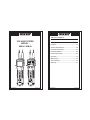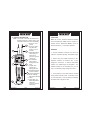
1
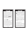
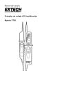
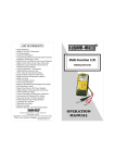
®
LIST OF PRODUCTS
*
*
*
*
*
*
*
*
*
*
*
*
*
*
*
*
*
*
*
*
*
*
*
*
*
*
*
*
*
*
Digital Multimeter
Digital AC & AC/DC Clampmeter
AC Clamp Adaptor
AC/DC Current Adaptor
Thermo Anemometer
Thermo Hygrometer
Distance Meter
Digital Lux Meter
Network Cable Tester
Power Factor Regulator
Earth Resistance Tester
Digital Panel Meters
DC Power Supplies
High Voltage Detector
Calibrators
Gas Analysers
Frequency Counter
Function Generator
Phasing Sticks
Battery Tester
Waterproof Pen Testers
Solar Power Meter
EMF Detector
Wood, Paper & Grain Moisture Meter
Transistorised Electronic Analog & Digital
Insulation Resistance Testers(upto 10 KV)
Digital Sound Level Meter & Sound Level
Calibrator
Digital contact & Non-contact Type Tachometer
Digital Non-contact (infrared) Thermometer
Maximum Demand Controller/Digital Power
Meter
Digital Hand Held Temperature Indicators
VOLTAGE TESTER
MODEL
KM 66 / KM 69
OPERATION
MANUAL
®
®
TABLE OF CONTENTS
TITLE
VOLTAGE TESTER
MODEL KM 66 / KM 69
PAGE
Safety Information.............................................01
Features.............................................................03
General Specifications.....................................03
Electrical Specification....................................05
Electrical Symbols............................................08
Product Description.........................................09
Operation...........................................................10
Maintenance......................................................18
Test Certificate..................................................20
H
EF
1000
690
400
230
120
50
24
12
6
1000
690
400
230
120
50
24
12
88.8
RCD
1000
690
400
230
120
50
24
12
6
30mA
230V
Warranty............................................................21
EF
1000
690
400
230
120
50
24
12
+V
~V
+V
~V
-V
EF
-V
EF
RCD
KUSAM-MECO
March 2013
KUSAM-MECO
March 2013
®
®
1. SAFETY INFORMATION
Terms in this manual
WARNING Identifies conditions & actions that
could result in serious injury or even
death to the USER.
CAUTION Identifies conditions & actions that
could cause damage or Malfunction in
the UNIT.
This manual contains information & warnings that
must be followed for operating the tester safely &
maintaining the tester in a safe operating
condition. If the tester is used in a manner not
specified by us, the protection provided by the
tester may be impaired. This tester meets water &
dust protection IP65 per outdoor type
requirements of IEC61243-3 (1998). Do not use
in rainfall ! The tester is protected, against the
users, by double insulation per EN61243-3(1998)
& EN61010-1 2nd Ed to CAT III 1000 & CAT IV
600V.
Per IEC61010-1 and IEC60664 :
Measurement Category IV (CAT IV) is for
measurements performed at the source of the
low-voltage installation. Examples are electricity
meters & measurements on primary overcurrent
protection devices and ripple control units.
KUSAM-MECO
01
March 2013
Measurement Category II (CAT II) is for
measurements performed on circuits directly
connected to the low voltage installation.
Examples are measurements on household
applicances, portable tools and similar equipment.
WARNING
To reduce the risk of fire or electric shock,do not
expose this product to rain or moisture. To avoid
electrical shock hazard, observe the proper
safety precautions when working with voltages
above 60VDC or 30 VAC rms. These voltage
levels pose a potential shock hazard to the user.
Keep your hands / fingers behind the hand / finger
barriers of the test probes that indicate the limits of
safe access of the hand-held part during
measurement. Inspect test probes, connectors,
and probes for damaged insulation or exposed
metal before using the tester. If any defects are
found, replace them immediately.
The voltages marked on the tester are nominal
voltages or nominal voltage ranges. The tester
shall only be used on installations with the specified
nominal voltages or nominal voltage ranges.
2) CENELEC DIRECTIVES
The tester conforms to CENELEC Low-voltage
directive 73/23/EEC and Electromagnetic
compatibility directive 89/336/EEC.
KUSAM-MECO
02
March 2013
®
®
?
For both models : Performance is specified in
an RF Field of 3V/m. Performance above
3V/m is not specified.
?
For KM 69 LCD display only : In an RF field of
3V/m, total accuracy = Specified accuracy +
45d. Performance above 3V/m is not specified.
?
Transient Protection :
Features :
?
High Input Impedance
?
Indicator Self- Test
?
Auto-Hold
?
Overload-Alert Warning
?
EF-Detection
?
AC-Detection Shaker (KM 69)
?
Bi-Color LED Hazardous Live Warning and
RCD Trip Test (KM 69).
SPECIFICATION
GENERAL SPECIFICATION
?
Sensing : Average sensing
?
Display : 3 digits 1000 Counts
?
Update Rate : 5 per second nominal
?
Operating Temperature : -10oC ~ 55oC
?
Relative Humidity: 20% ~ 96%
?
APO Consumption (typical) : 10m
A
?
Dimension : 233 (L) x 57 (W) x 40 (H) mm
?
Weight : Approx. 220gm
?
Altitude : Operating below 2000m
o
8KV lightning surge (1.2/50m
s)
?
Overload Protection : 1000VDC & VAC rms.
?
Low Battery: Below approx. 2.4V;
Below approx. 2.6V for KM 69 with shaker ON
?
Power Supply: Standard 1.5V AAA size x 2;
or 1.5V AAA size alkaline battery x 2
?
APO Timing: Idle for 15 seconds
?
Power Consumption (typical) : 3mA at
Power-on ready; 25mA at 1000VAC full LED
indication. 75mA at 1000VAC with shaker ON
(KM 69)
o
?
Storage Temperature : -10 C ~ 55 C,
20% ~ 96% R.H. (With battery removed)
?
Temperature Coefficient : Nominal 0.15 x
?
Safety : Meets En61243 voltage class
(specified accuracy) / oC @ (-10oC ~ 18oC or
B,
EN61010-1 and IEC61010-1 2nd
28oC ~ 55oC), or otherwise specified.
Edition to CAT III 1000V & CAT IV 600V.
?
Measurement Category: CAT III 1000V &
CAT IV 600V AC & DC
?
E.M.C. : Meets EN61326 (1997, 1998/A1),
EN61000-4-2 (1995), & EN61000-4-3 (1996):
?
Type of Protection : IP65
ACCESSORIES: Batteries installed, User manual,
?
Pollution Degree : 2
Test leads pair.
KUSAM-MECO
03
March 2013
KUSAM-MECO
04
March 2013
®
®
ELECTRICAL SPECIFICATIONS :
Audible Continuity
Accuracy is given as +/- (% of reading digits +
number of digits) or otherwise specified
@ 23oC +/- 5oC and less than 75% R.H.
Open Circuit Voltage
0.4 VDC typical
between 50KW
&
2000KW
.
Audible Threshold
DC & AC Voltage (LED)
DCV
MARKING
ACV
MARKING
6V
TYPICAL
THRESHOLD
4.8V
DC & AC Voltage (KM 69 LCD only)
12V
12V
9.6V
24V
24V
19.2V
50V
50V
40V
120V
120V
96V
230V
230V
184V
400V
400V
320V
690V
690V
552V
1000V
1000V
800V
Range
DC 999V
AC 999V
(50Hz/60Hz)
Threshold
Accuracy
> +4.5VDC or ±(1.0%rdg + 2dgts)
< -4.5VDC
> 8VAC
±(2.5%rdg + 4dgts)
Input Impedance : 460KW
, 160pF nominal
Duty Ratio : Continuous duty
LED Threshold : < 85% of Voltage marking.
Typical @ 80%
Input Impedance : 460KW
, 160pF nominal.
ACV Frequency Response : 45Hz ~ 65Hz
Duty Ratio : Continuous duty.
Non-Contact EF-Detection
AC Detection Shaker Threshold (KM 69 only)
Shaker ON
> 15VAC
Shaker OFF
< 8VAC
KUSAM-MECO
05
March 2013
Indication : EF LED flashing & audible beep tones
proportional to the field strength
Detection Frequency : 50/60Hz
Detection Antenna : Top-right side of the meter
Probe-Contact EF-Detection : For more precise
indication of live wires, such as distinguishing
between live & ground connections, use the Red(+)
test probe for direct contact measurements.
KUSAM-MECO
06
March 2013
®
®
KM 69 also displays Bar graph segments
INTERNATIONAL ELECTRICAL SYMBOLS
proportional to the field strength on LCD. Typical
Caution ! Refer to the explanation in this
Manual.
Values are shown in the following table :
Typical Non-Contact
Voltage Range
LCD Bar Graph Indication
KM 69
7 Caution ! Risk of electric shock
Earth (Ground)
15V to 55V
30V to 95V
Double Insulation or Reinforced insulation
55V to 170V
Fuse.
~
Above 120V
AC--Alternating Current
DC--Direct Current
RCD Leakage-Path (KM 69 only)
Load Current
30mA typical at 230V
7.7 kW
nominal,
PTC protected
Path Impedance
RCD Leakage-Path feature is intended for 230V
nominal Circuits only.
It is disabled above 270V and below 120V.
KUSAM-MECO
07
March 2013
KUSAM-MECO
08
March 2013
®
®
3) PRODUCT DESCRIPTION
OPERATION
Note : The model is used as representative for
illustration purpose. Please refer to your
respective model for function availability.
1. Screw-on 4mm
test tip
1
2. Screw-on stationary Red test
probe (+) for all
function.
2
3
3. Detachable Black
test probe(-) for
all functions
(Common ground
H
4
reference)
5 4. EF- Detection
(Non-contact
RCD
Voltage) antenna
EF
7
6
area.
5. 3 digits 1000
counts LCD
1000
1000
690
690
display (KM 69)
400
400
6. EF-Detection(Non230
230
120
120
Contact & Probe50
50
8 Contact)test button.
24
24
12
12
7. RCD Leakage 6
+V
Path button(KM 69)
~V
-V
EF
8. LEDs
RCD
9. Input Jack(-) for
Detachable Black
9
test probe
(Common ground
reference)
88.8
30mA
230V
KUSAM-MECO
09
March 2013
Note : All function operations described hereafter
are via the stationary “Red” probe for positive (+)
polarity and the detachable “Black” probe for
Ground reference (-), or otherwise specified.
WARNING
?
Accurate indication is assured only when use
within the specified operating temperature range.
?
Before using the Audible Continuity & EFDetection features at locations with a high
backgroud noise level, it shall be determined
whether the audible signal is perceptible. The
audible indication is for information only; do not
rely on it, especially in high background noise.
?
The functioning of the tester shall be checked
shortly before and after a test. If indication of one
or more steps fails, or if no functioning is indicated,
the tester shall no longer be used.
KUSAM-MECO
10
March 2013
®
®
~
When significant ACV is being tested, V LED turns
Indicator Self-Test
Short the two test probes together, the tester enters
continuity function. The continuity LED will turn on
and the beeper will sound. With the probes still
shorted, press the EF button momentarily.
The
LEDs will illuminate for full indication check. On the
KM 69, five voltage indicating bi-color LEDs will
change from green to red, and the LCD will turn on
~
for full segment check. The
, +V , - V , & V LEDs
flash twice additionally when the battery voltage is
low. After the Self-test is finished in approx. 2 to 3
seconds, the tester resumes normal functions.
on.
When significant DCV is being tested, +V
LED turns on for correct test probes polarity, and
- V LED turns on for reversed polarity. Significant
voltage levels are indicated as a series of LEDs in
an autoranging manner.
selection is required.
No manual-ranging
KM 69 also indicates
voltage levels on the automatic backlighted LCD.
Note : The voltage indicating LEDs are all
powered by the internal batteries, not by the
system under test.
The input impedance on
voltage testing function is as high as 460KW
, and
hence the influence of the measuring current on
the system under test is negligible.
~
ACV (V) and DCV (V) functions
The peak
occurring current/s at the highest rated voltage
Perform Indicator Self-Test as described. Test the
tester on a known functioning circuit or component
1000VAC is :
Is = 1000V x1.414 / 460000W
= 2.5mA
before and after performing measurements.
Connect test probes to voltage source and observe
indication, as shown. Do not cover indicating LEDs
(and also LCD on KM 69) and do not touch the
contact electrode before and during the tests. The
tester truns on automatically at threshold voltages
as specified in the specification section.
RCD Leakage-Path (KM 69 only)
The tester equips with an RCD Leakage-Path
feature to load 230VAC / 30mA RCD (Residual
Current Devices) circuit breakers.
An internal
leakage load path is provided when this feature is
activated.
Nominal load impedance is 7.7KW
to
provide typical leakage current of 30mA at 230VAC.
KUSAM-MECO
11
March 2013
KUSAM-MECO
12
March 2013
®
®
?
Connect the tester to the receptacle under test
by measuring the voltage across L and PE (live
conductor and a protective earth ground). The
tester should indicate proper line voltage level.
(RCD Leakage-Path feature is disabled above
270V and below 120V).
Effectiveness of RCD circuit breakers should be
checked by RCD testing, measuring or
monitoring equipments under the scope of
IEC61557-1 & IEC61557-6.
+ DCV -
?
With the proper line voltage level still indicating,
press and hold the RCD button on the tester. The
tester continuity / RCD LED will turn on to indicate
the internal leakage load path is being connected.
012
RCD
30mA
230V
~
238
Note : This feature merely provides a handy
leakage load path to load RCD circuit breakers. It
is not intended to identify the effectiveness (trip
current & trip time etc as specified by the breaker
manufacturers) of breakers even though the
breakers trip under the above mentioned leakage
conditions.
KUSAM-MECO
13
March 2013
1000
1000
690
690
400
400
230
230
120
120
50
50
24
24
12
12
6
+V
-V
~
238
EF
RCD
?
The LED will turn off when the RCD circuit
breaker trips (line voltage is cut off). If an RCD
circuit breaker does not trip (within a fraction of a
second) under such a leakage load condition, it is
pretty sure that the breaker is not working properly
or there is a wiring problem.
RCD
ACV
~V
EF
30mA
230V
RCD
EF
30mA
230V
EF
1
1000
690
400
230
120
50
24
12
6
1000
690
400
230
120
50
24
12
1000
1000
690
690
400
400
230
230
120
120
50
50
24
24
12
12
6
+V
~V
+V
-V
EF
-V
~V
EF
RCD
RCD
RCD
Overload-Altert Warning
When the measured voltage exceeded 1000V AC
or DC, the 1000V LED flashes. The KM 69 LCD
also displays “OL”. Disconnect the test probes from
the test probes from the signal immediately to avoid
hazards.
KUSAM-MECO
14
March 2013
®
®
EF (NCV)
Bi-Color LED Hazardous Live Warning
(KM 69 only)
EF
This voltage LEDs are red if the measured voltage
is above 70VDC /33VAC. These levels are
deemed to be hazardous live in normal condition.
Below these levels, the LEDs are green.
Auto-Hold
RCD
30mA
230V
EF
RCD
1000
690
400
230
120
50
24
12
1000
690
400
230
120
50
24
12
6
30mA
230V
EF
RCD
The LEDs flash the last significant measured value
for approx. 10 seconds after a voltage
measurement is made and removed via the test
probes. The KM 69 LCD also flashes the last
significant measured value. Both test probes
should be removed from the test points at about
the same time (<0.5 second in time difference) or
else lower (intermittent) voltage might be
measured.
1000
690
400
230
120
50
24
12
6
1000
690
400
230
120
50
24
12
+V
~V
+V
~V
-V
EF
-V
EF
RCD
RCD
1000
690
400
230
120
50
24
12
6
30mA
230V
EF
1000
690
400
230
120
50
24
12
+V
~V
-V
EF
RCD
AC-Detection Shaker (KM 69 only)
The shaker signals that significant ACV is being
measured via the test probes.
With no input, press and hold the RCD button and
then followed by the EF button to toggle the shaker
On/OFF. The shaker will remain on until the
buttons are released to confirm that the ACDetection Shaker feature is enabled. The shaker
will turn on briefly to signal that this feature has
been disabled.
KUSAM-MECO
15
March 2013
Electric Field EF-Detection :
Press and hold the EF button to enter and stay at
EF-Detection feature. The EF-indicating LED will
turn on briefly, and the beeper will give a short beep
for EF indication check.
Signal strength is
indicated by beep tone and flashing of the EF LED.
The KM 69 also display “EF” when it is ready, and
displays signal strength as a series of bar-graph
segments on the LCD.
KUSAM-MECO
16
March 2013
®
®
?
Non-Contact EF-Detection : An antenna
is located along the top-right side of the meter
which detects electric field surrounds currentcarrying conductors. It is ideal for tracing live wiring
connections, locating wiring breakage and to
distinguish between live or earth connections.
?
Probe-Contact EF-Detection : For more
precise indication of live wires, such as
distinguishing between live and ground
connections, use the Red (+) test probe for direct
contact measurements.
MAINTENANCE
WARNING
To avoid electrical shock, disconnect the tester
from any circuit and remove the test probes from
the input jacks before opening the case and / or the
battery access door. Do not use the tester with
open case and / or the battery access door. Do not
attempt to repair this unit. It contains no userserviceable parts. Unauthorized persons shall not
disassemble the tester.
Cleaning and Storage
Audible Continuity Function
Short the two test probes together for continuity
function check as described in indicator Self-Test
section. The continuity LED turns on together
with a continuous beep tone indicates a complete
circuit is being detected via the test probes.
Audible-Continuity is convenient for checking
wiring connections and operation of switches.
Auto Power On & Auto Power Off (APO)
The tester turns on automatically within 1 second
when making significant measurement or push
button activity. Allow this delay on the “wake-up”
measurement.
The tester turns off intelligently after approx.
15 seconds of neither significant measurement
nor button / switch activity.
KUSAM-MECO
17
March 2013
Periodically wipe the case with a damp cloth and
mild detergent; do not use abrasives or solvents.
The tester should be kept dry and clean. If the
tester is not to be used for periods of longer than 60
days, remove the batteries and store them
separately.
Trouble Shooting
If the tester fails to operate, check batteries, probes
etc., and replace as necessary. Double check
operating procedure as described in this user’s
manual.
If the tester voltage-continuity input has subjected
to high voltage transient (mostly caused by lighting
or switching surge to your system) by accident or
abnormal conditions of operation, the series fusible
resistors will be blown off (become high
impedance) like fuses to protect the user and the
KUSAM-MECO
18
March 2013
®
®
tester. Most measuring functions through this input
will then be open circuit. The series fusible resistors
and the spark gaps should then be replaced by
qualified technician.
MUMBAI
TEST CERTIFICATE
VOLTAGE TESTER
Battery replacement
The batteries should be checked before use.
When the battery voltage is low, the
+V , - V
,~V or LED flashes under normal signficant
measurements. KM 69 also displays low battery
icon + - on the LCD under normal significant
measurements. Replace the batteries ASAP to
maintain tester accuracy and functionality. The
tester uses two 1.5V batteries : Standard 1.5V
AAA size battery X 2; or 1.5V AAA size alkaline
battery X 2.
Loosen the 2 screws from the battery access door
of the case bottom. Lift the battery access door up.
Replace the batteries. Refasten the screws.
This Test Certificate warrantees that
the product has been inspected and
tested in accordance with the published
specifications.
The instrument has been calibrated by
using equipment which has already
been calibrated to standards traceable
to national standards.
MODEL NO. ___________
SERIAL NO. ___________
DATE: ___________
QC
ISO 9001
REGISTERED
KUSAM-MECO
19
March 2013
KUSAM-MECO
KUSAM-MECO
PASS
20
March 2013
®
®
WARRANTY
Each “KUSAM-MECO” product is warranted to be
free from defects in material and workmanship
under normal use & service. The warranty period
is one year (12 months) and begins from the date
of despatch of goods. In case any defect occurs in
functioning of the instrument, under proper use,
within the warranty period, the same will be
rectified by us free of charges, provided the to and
fro freight charges are borne by you.
This warranty extends only to the original buyer or
end-user customer of a “KUSAM-MECO”
authorized dealer.
This warranty does not apply for damaged Ic’s,
fuses, burnt PCB’s, disposable batteries, carrying
case, test leads, or to any product which in
“KUSAM-MECO’s” opinion, has been misused,
altered, neglected, contaminated or damaged by
accident or abnormal conditions of operation or
handling.
“KUSAM-MECO” authorized dealer shall extend
this warranty on new and unused products to enduser customers only but have no authority to
extend a greater or different warranty on behalf of
“KUSAM-MECO”.
KUSAM-MECO
21
March 2013
“KUSAM-MECO’s” warranty obligation is limited,
at option, free of charge repair, or replacement of
a defective product which is returned to a
“KUSAM-MECO” authorized service center within
the warranty period.
THIS WARRANTY IS BUYER’S SOLE AND
EXCLUSIVE REMEDY AND IS IN LIEU OF ALL
OTHER WARRANTIES, EXPRESS OR IMPLIED,
INCLUDING BUT NOT LIMITED TO ANY IMPLIED
WARRANTY OF MERCHANTABILITY OR
FITNESS FOR A PARTICULAR PURPOSE.
“KUSAM-MECO” SHALL NOT BE LIABLE FOR
ANY SPECIAL, INDIRECT, INCIDENTAL OR
CONSEQUENTIAL DAMAGES OR LOSSES,
INCLUDING LOSS OF DATA, ARISING FROM
ANY CAUSE WHATSOEVER.
All transaction are subject to Mumbai Jurisdiction.
®
G 17,Bharat Industrial Estate, T. J. Road,
Sewree (W), Mumbai - 400 015. INDIA.
Sales Direct : (022) 24156638
Tel. : (022) 24124540, 24181649.
Fax : (022) 24149659
Email : [email protected]
Website : www.kusamelectrical.com
www.kusam-meco.co.in
KUSAM-MECO
March 2013