1
CT
OR
, IN
C.
200
5
Freescale Semiconductor, Inc.
MIC
ON
DU
Freescale Semiconductor, Inc...
Motorola
Digital Signal
Processors
LE
SE
DSP56001 Interface
Techniques and Examples
CH
IVE
DB
YF
RE
ES
CA
by
Roman Robles
Digital Signal Processor Operation
AR
MOTOROLA
For More Information On This Product,
Go to: www.freescale.com
APR11
CT
OR
, IN
C.
200
5
DU
ON
MIC
SE
LE
CA
CH
IVE
DB
YF
RE
ES
Motorola reserves the right to make changes without further notice to any products herein. Motorola makes no warranty, representation or guarantee regarding the suitability of
its products for any particular purpose, nor does Motorola assume any liability arising out
of the application or use of any product or circuit, and specifically disclaims any and all
liability, including without limitation consequential or incidental damages. “Typical” parameters can and do vary in different applications. All operating parameters, including
“Typicals” must be validated for each customer application by customer’s technical experts. Motorola does not convey any license under its patent rights nor the rights of others. Motorola products are not designed, intended, or authorized for use as components
in systems intended for surgical implant into the body, or other applications intended to
support or sustain life, or for any other application in which the failure of the Motorola
product could create a situation where personal injury or death may occur. Should Buyer
purchase or use Motorola products for any such unintended or unauthorized application,
Buyer shall indemnify and hold Motorola and its officers, employees, subsidiaries, affiliates, and distributors harmless against all claims, costs, damages, and expenses, and
reasonable attorney fees arising out of, directly or indirectly, any claim of personal injury
or death associated with such unintended or unauthorized use, even if such claim alleges
that Motorola was negligent regarding the design or manufacture of the part. Motorola
and
are registered trademarks of Motorola, Inc. Motorola, Inc. is an Equal Opportunity/Affirmative Action Employer.
AR
Freescale Semiconductor, Inc...
Freescale Semiconductor, Inc.
For More Information On This Product,
Go to: www.freescale.com
CT
OR
, IN
C.
200
5
Freescale Semiconductor, Inc.
1-4
1-5
1-8
1-11
2-6
2-9
2-12
CA
LE
A Simple Dynamic
RAM Interface for
the DSP56001
2.1 Circuit Overview
2.2 Circuit Description
2.3 Summary
SE
SECTION 2
DSP56001 Memory I/O Basics
Memory Subsystem Overview
Circuit Description
Summary
MIC
Interfacing
Motorola’s
DSP56001 to
Pseudo Static RAM
DU
1.1
1.2
1.3
1.4
ON
SECTION 1
SECTION 3
RE
ES
A Simple ISA Bus
Interface for the
DSP56001
YF
SECTION 4
3-1
3-3
3-4
4.1 Introduction
4.2 Example Program
4-1
4-1
DB
Communicate with
the DSP56000 Host
Interface Using
C Language
3.1 Interface Circuit Overview
3.2 Detailed Circuit Description
3.3 Timing
CH
IVE
INDEX
REFERENCES
MOTOROLA
AR
Freescale Semiconductor, Inc...
Table
of Contents
For More Information On This Product,
Go to: www.freescale.com
Index-1
Reference-1
iii
AR
CH
IVE
DB
YF
RE
ES
CA
LE
SE
MIC
ON
DU
Freescale Semiconductor, Inc...
CT
OR
, IN
C.
200
5
Freescale Semiconductor, Inc.
For More Information On This Product,
Go to: www.freescale.com
CT
OR
, IN
C.
200
5
Freescale Semiconductor, Inc.
Pseudo Static RAM Auto Refresh Timing
Figure 1-2
DSP56001-to-PSRAM Schematic
1-6
Figure 1-3
PSRAM Interface State Diagram
1-9
Figure 1-4
DSP56001-to-PSRAM Timing
1-10
Figure 1-5
DSP56001-to-PSRAM PLD Definition
1-13
Figure 1-6
PSRAM Interface Initialization Code
1-14
Figure 2-1
DRAM Memory Address Multiplexing
2-3
Figure 2-2
DRAM Refresh Modes
2-4
Figure 2-3
DSP56001-to-DRAM Timing
2-5
Figure 2-4
DSP56001-to-DRAM Schematic
2-8
Figure 2-5
DRAM Interface State Diagram
2-10
Figure 2-6
PLD Design File -DRAM Interface
2-13
Figure 2-7
DRAM Interface Initialization Code
2-15
DSP56001-to-ISA Bus Interface Schematic
3-2
Figure 3-2
PLD Definition for the ISA Bus Interface
3-6
Figure 3-3
DSP56001-to-ISA Bus Interface Timing
3-8
Figure 4-1
Example Program of DSP56000 Host Interface
Using C Language
4-4
ON
MIC
SE
LE
CA
ES
CH
IVE
DB
YF
RE
Figure 3-1
DU
Figure 1-1
MOTOROLA
AR
Freescale Semiconductor, Inc...
Illustrations
For More Information On This Product,
Go to: www.freescale.com
1-3
AR
CH
IVE
DB
YF
RE
ES
CA
LE
SE
MIC
ON
DU
Freescale Semiconductor, Inc...
CT
OR
, IN
C.
200
5
Freescale Semiconductor, Inc.
For More Information On This Product,
Go to: www.freescale.com
DU
Interfacing
Motorola’s DSP56001
to Pseudo Static RAM
When the design definition of a DSP subsystem calls
ON
“PSRAM
for a large memory space, the cost of populating this
space with static RAM (SRAM) can be prohibitive. Although SRAM offers the advantages of high speed and
a very simple interface, the complex structure of the
SRAM storage cell results in SRAM price/density ratios
which are inferior to those of dynamic RAM. Pseudo
Static RAM (PSRAM) presents one possible compromise between the contradictory requirements of high
density, low cost, high speed and interface simplicity.
combines the
MIC
economies of
DRAM with the
SE
straightforward
interface of fully
LE
Static RAM to
provide 128K
This section presents a simple implementation of a
PSRAM interface to the DSP56001. Using an array of
three 128K x 8 PSRAMs, the circuit provides access
to 128K 24-bit words of data space. With the
DSP56001 operating from a 33MHz clock, this memory subsystem will operate with 2 wait states for nonconsecutive accesses.
CH
IVE
DB
YF
RE
ES
DIP.”
CA
bytes in a 32-pin
MOTOROLA
AR
Freescale Semiconductor, Inc...
SECTION 1
CT
OR
, IN
C.
200
5
Freescale Semiconductor, Inc.
For More Information On This Product,
Go to: www.freescale.com
1-1
CT
OR
, IN
C.
200
5
Freescale Semiconductor, Inc.
ON
DU
PSRAM combines the economies of DRAM with the straightforward interface of fully
Static RAM to provide 128K bytes in a 32-pin DIP. Internally, the device contains a dynamic RAM array with on-board address multiplexing, an internal refresh row counter,
and an internal refresh timer. The memory array is divided into eight sections, each consisting of a of 512 (row) x 256 (column) matrix of storage cells, forming a byte-wide
memory which is 128K locations deep.
MIC
The device is pin compatible with the 128Kx8 SRAM JEDEC pinout with the exception
of pin 1 (on standard SRAMs, this pin would be a no-connect; on PSRAM, it is the refresh strobe F). These features enable the PSRAM to replace fully static RAM in many
applications with a minimum amount of “glue”.
SE
PSRAM has two complementary enable lines, E1 and E2. During read and write operations, these enable lines must strobe the address into the device. This is another difference
between PSRAM and fully static RAM.
CA
LE
Since the PSRAM is based on DRAM storage elements, it requires a precharge delay
between successive accesses and a periodic refresh. PSRAM supports three different refresh modes; CE-only refresh, auto refresh and self refresh.
RE
ES
• CE-only refresh requires external hardware or software to provide periodic
addressing of each of the 512 rows. Use of this method would add a
considerable amount of interface hardware or would cause significant
degradation to software performance.
1-2
CH
IVE
DB
YF
• Self refresh can be entered after 8 ms in standby mode. In this mode the onboard refresh timer and refresh counter are used to provide the refresh
sequencing. A delay slightly greater than one access cycle is required when
leaving this mode before data read/write operations can proceed. This mode
is useful for long standby periods, but is not suitable for device refresh during
periods of normal DSP activity due to the unique timing requirements. To use
this mode during idle periods would require mode selection logic as well as
the circuitry associated with one of the other “active access” modes.
AR
Freescale Semiconductor, Inc...
Pseudo-Static RAM
MOTOROLA
For More Information On This Product,
Go to: www.freescale.com
CT
OR
, IN
C.
200
5
DU
• Auto refresh occurs when the PSRAM is disabled by either of the
device select inputs going false followed by the refresh pin F going
active. For each transition of F, one row of each section is refreshed and
the refresh row counter is advanced in preparation for the next refresh
cycle. The example presented in this note uses this mode because it
requires the least amount of external logic and impacts the normal DSP
software only when a data transfer contends with a refresh cycle.
LE
SE
MIC
ON
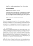
Figure 1-1 depicts an auto refresh cycle in which two rows are refreshed in succession. Note that either E1 or E2 can disable the device. Refer to the data sheets
specific to the PSRAMs selected for any particular application.
E1
CA
E2
-or-
ES
E1
RE
E2
YF
F
CH
IVE
DB
Figure 1-1 Pseudo Static RAM Auto Refresh Timing in which 2 rows are refreshed in succession. Note that either E1 or E2 can disable the
device. Please refer to the data sheets specific to the PSRAMs
selected for any particular application.
MOTOROLA
AR
Freescale Semiconductor, Inc...
Freescale Semiconductor, Inc.
For More Information On This Product,
Go to: www.freescale.com
1-3
CT
OR
, IN
C.
200
5
Freescale Semiconductor, Inc.
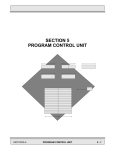
1.1 DSP56001
Memory I/O Basics
ES
CA
LE
SE
MIC
ON
DU
Freescale Semiconductor, Inc...
Memory interface to the DSP56001 occurs over Port A
of the processor. Port A consists of 24 bi-directional
data lines (D0-D23), 16 address lines (A0-A15), three
memory reference lines (PS,DS, X/Y) and two data
strobes (RD, WR). Additionally, a pair of bus access
control signals, Bus Request/Bus Grant (BR/BG), can
be used to synchronize access requests between the
processor and another device attempting to gain
mastership of the bus. The bus access pins have alternate functions, Bus Strobe /Wait (BS/WT), which
allow external circuitry to insert additional wait states
in external bus cycles. To minimize power consumption, the address lines remain stable until the
beginning of the next external access. The memory
reference signals (PS, DS and X/Y) are deasserted
during periods when the external bus is idle, but are
not deasserted during successive accesses to the
same external memory space.
AR
1-4
CH
IVE
DB
YF
RE
Setting bit 7 of the processor’s Operating Mode Register (OMR) causes the bus access control bits to
assume the Bus Strobe/Wait (BS/WT) mode. In this
mode, the BS pin is asserted at the beginning of every
external access and is released during T3 of each external cycle. Assertion of the WT pin during T2 while
BS is asserted adds wait states to the bus cycle.
Wait states will continue to be inserted until two falling
edges of EXTAL occur in succession with the release of
WT. WT should never be asserted when BS is inactive.
MOTOROLA
For More Information On This Product,
Go to: www.freescale.com
CT
OR
, IN
C.
200
5
DU
When the DSP56001 is reading data from the bus, the
data must be stable for the specified setup and hold
periods before and after (respectively) the rising edge
of the read strobe RD. During processor write operations to the external bus, the data is valid for a
specified time before and after the rising edge of the
write strobe WR.
SE
MIC
ON
These relationships in are shown in the simplified
PSRAM timing diagram of Figure 1-4. (For DRAM timing see Figure 2-3.) For more detailed information,
refer to the DSP56001 User’s Manual and the
DSP56001 Data Sheet.
LE
1.2 Memory Subsystem
Overview
YF
RE
ES
CA
The circuit in Figure 1-2 is designed to serve as an extension of the Motorola DSP56000 ADS Application
Development Module (ADM). The Static RAM on the
ADM should be configured to reside solely within the
DSP56001 program space. The PSRAMs and their
interface circuitry are attached to the DSP56001’s
Data and Address Buses via ADM connector J3.
CH
IVE
DB
The PSRAM bank consists of three devices. Each device
provides 128K storage cells for each of 8 data bits, forming an array of 128K 24-bit words. The DSP56001 can
address 64K 24-bit words in each of its two data spaces,
X:memory and Y: memory. Therefore, this PSRAM array
fully populates both of the processor’s data spaces.
MOTOROLA
AR
Freescale Semiconductor, Inc...
Freescale Semiconductor, Inc.
For More Information On This Product,
Go to: www.freescale.com
1-5
AR
1-6
CH
IVE
DB
YF
RE
ES
CA
LE
SE
MIC
ON
DU
Freescale Semiconductor, Inc...
CT
OR
, IN
C.
200
5
Freescale Semiconductor, Inc.
MOTOROLA
For More Information On This Product,
Go to: www.freescale.com
+5v
13 14 15 17 13 14 15 17 13 14 15 17
D00
D01
D02
D03
D00
D01
D02
D03
D00
D01
D02
D03
15K
G
W
A0
A1
A2
A3
A4
A5
A6
A7
A8
A9
A10
A11
A12
A13
A14
A15
A16
E1
F
3
4
B28
DS
B30
BS
PRE
5
2
D
Q
A
3
CK
Q
CLR
6
1
DU
LE
D04
D05
D06
D07
D12
D13
D14
D15
D20
D21
D22
D23
CA
A20
A19
A18
A17
A12
A11
A10
A09
A04
A03
A02
A01
+5v
+5v
MC74AC74
10
PRE
Q 9
12
D
11
CK
B
Q
CLR
8
13
DB
+5v
C23
ES
4
REFRESH CYCLE STROBE
REFRESH REQUEST
RE
OE*
YF
11
BUSY-CLR
19
2
13
18
4
3
15
MEMORY BUSY
PAL16R4-7
WT
(80 ns)
18 19 20 21 18 19 20 21 18 19 20 21
1
B29
3 - 128K x 8
PSEUDO STATIC
RAM
30
D04
D05
D06
D07
D04
D05
D06
D07
D04
D05
D06
D07
MC74AC04
B05 CLOCK
E2
ON
24
29
12
11
10
9
8
7
6
5
27
26
23
25
4
28
3
31
2
22
1
MIC
RD
WR
AD00
AD01
AD02
AD03
AD04
AD05
AD06
AD07
AD08
AD09
AD10
AD11
AD12
AD13
AD14
AD15
X/Y
SE
B25
B24
C16
C15
C14
C13
C12
C11
C10
C09
C08
C07
C06
C05
C04
C03
C02
C01
B26
SCLK
CH
IVE
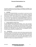
Figure 1-2 DSP56001-to-PSRAM Schematic provides two functions:
it controls the refresh cycles and it generates precharge delays.
This is a schematic depiction of the interface circuit.
MOTOROLA
AR
Freescale Semiconductor, Inc...
NOTE:
CONNECTOR is J3 of DSP56000 ADM
CT
OR
, IN
C.
200
5
D00
D01
D02
D03
D08
D09
D10
D11
D16
D17
D18
D19
A24
A23
A22
A21
A16
A15
A14
A13
A08
A07
A06
A05
Freescale Semiconductor, Inc.
For More Information On This Product,
Go to: www.freescale.com
1-7
CT
OR
, IN
C.
200
5
Freescale Semiconductor, Inc.
SE
MIC
ON
DU
Freescale Semiconductor, Inc...
In order to minimize the component count, the refresh request timing is supplied by the processor’s
Serial Control Interface (SCI) clock, SCLK. Initialization software configures this clock to provide a
pulse train with a 15 µs period. Once initialized, the
generation of this signal is completely transparent
to any code executing on the processor. Figure 1-6
is a listing of the initialization code and a short
“pass/fail” memory test routine. The value loaded
into the SCI Clock Control Register (SCCR) at
X:$FFF2 will vary as a function of the system clock
frequency. For a 33 MHz clock, a value of $107F
will yield the desired refresh rate of 15.6 µs per row.
ES
CA
LE
A second task of the initialization software is the selection of the BS/WT mode of operation. This mode
allows an external source to insert wait states into
bus cycles, and is employed by the interface when
precharge and refresh delays are needed.
AR
1-8
CH
IVE
DB
YF
RE
The interface operates from the same clock which
drives the processor. In systems operating from an
external clock source, this should be easy to provide.
In this example, the DSP56001 clock is buffered by a
CMOS inverter which subsequently drives the interface circuitry. It is essential that the device used to
buffer this clock has a very high input impedance.
The oscillator on the DSP56001 cannot drive a TTL
input load.
MOTOROLA
For More Information On This Product,
Go to: www.freescale.com
CT
OR
, IN
C.
200
5
Freescale Semiconductor, Inc.
1.3 Circuit Description
CA
LE
SE
MIC
ON
DU
Section “B” of the MC74AC74 generates a refresh request on the rising edge of SCLK and holds the
request until the PAL16R4-7 controller executes a refresh cycle and resets the Flip-Flop. As shown in
Figure 1-3, the controller defers a refresh cycle until
any access currently in progress completes. If the
subsequent DSP56001 instruction cycle does not access this PSRAM array, this refresh is transparent. If
the subsequent cycle does access this area of memory, then wait states are inserted until the refresh
completes.
CH
IVE
DB
YF
RE
ES
Section “A” of the MC74AC74 is clocked by the rising
edge of BS, which occurs at the end of each external
bus cycle. In the event that the bus cycle which has
just ended was an active cycle for the PSRAM array,
the PSRAM address decode (DS in this example) will
be latched into Flip-Flop “A”. The PLD will receive
MEMORY BUSY status, indicating that a pre-charge
cycle is in progress. The PLD will hold off further
PSRAM activity until sufficient precharge delay has
elapsed. Note that no extra delay is seen by the
DSP56001 if the subsequent cycle does not access
this particular PSRAM. If multiple banks of PSRAM
are used, bank interleaving strategies can result in
most (or all) of the precharge cycles being hidden
MOTOROLA
AR
Freescale Semiconductor, Inc...
Figure 1-2 is a schematic depiction of the interface
circuit. Basically, the interface provides two functions:
it controls the refresh cycles and it generates precharge delays.
For More Information On This Product,
Go to: www.freescale.com
1-9
CT
OR
, IN
C.
200
5
Freescale Semiconductor, Inc.
behind activity in complementary memory banks.
Similarly, if the DSP56001 is executing code out of an
external SRAM in another bank, the precharge activity would be transparent.
SE
MIC
ON
DU
Freescale Semiconductor, Inc...
The ABELTM1 design file for the PAL16R4-7 is a very
simple Mealy type state machine (see Figure 1-5). It
controls the chip enabling of the PSRAM as well as
the assertion of WT, which goes to the DSP56001 to
hold off bus activity. In addition, the machine provides
resets for the external latches. The function of the
PLD is shown in the state diagram of Figure 1-3.
!Refresh Req &!BUSY
LE
IDLE
FIM
Pre2
Refresh Req
!Refresh Req
DB
IVE
CH
AR
1-10
RF6
RF5
RF3
YF
RE
ES
CA
Pre1
RF4
Figure 1-3 PSRAM Interface State Diagram implemented in a single PAL
1. ABEL is a trademark of the data I/O Corporation
MOTOROLA
For More Information On This Product,
Go to: www.freescale.com
CH
IVE
DB
YF
RE
ES
CA
LE
SE
MIC
ON
DU
Freescale Semiconductor, Inc...
CT
OR
, IN
C.
200
5
Freescale Semiconductor, Inc.
AR
MOTOROLA
For More Information On This Product,
Go to: www.freescale.com
1-11
CT
OR
, IN
C.
200
5
Freescale Semiconductor, Inc.
T0 T1 T2 Tw Tw Tw Tw T3 T0 T1 T2 Tw Tw Tw Tw Tw Tw T3 T0
EXTAL
Freescale Semiconductor, Inc...
ADDR
DU
E
ON
BS
MIC
BUSY
SE
WT
LE
RD
to DSP
to DSP
CA
D0-23
ES
WR
DATA to PSRAM
RE
D0-23
IDLE
IDLE
IDLE
IDLE
Pre1
Pre2
FIM
IDLE
IDLE
DB
YF
STATE
DATA to PSRAM
AR
1-12
CH
IVE
Figure 1-4 DSP56001-to-PSRAM Timing shows the operation of the controller
as it progresses through a pair of successive memory accesses.
The timing diagram in Figure 1-4 shows the operation
MOTOROLA
For More Information On This Product,
Go to: www.freescale.com
CH
IVE
DB
YF
RE
ES
CA
LE
SE
MIC
ON
DU
Freescale Semiconductor, Inc...
CT
OR
, IN
C.
200
5
Freescale Semiconductor, Inc.
AR
MOTOROLA
For More Information On This Product,
Go to: www.freescale.com
1-13
CT
OR
, IN
C.
200
5
MIC
ON
DU
|module
pseudo
|title’Pseudo-Static RAM Timing Controller Ver.1
|
MOTOROLA INC.
17 July 1990’
|
|
U01
device’P16R4’;
|
|“INPUTS
|
CLK
pin
1;
“DSP56001 Clock “
|
CSin
pin
2;
“EXT:RAM Address decode”
|
Busy
pin
3;
“BUSY F/F”
|
Rreq
pin
4;
“latched request for refresh cycle”
|
|
OE
pin
11;
“OE*”
|
|“OUTPUTS”
“----REGISTERED OUTPUTS----”
|
Q0
pin
17;
“State bit 0"
|
Q1
pin
16;
“State bit 1"
|
Q2
pin
15;
“State bit 2 & Busy_clr”
|
Q3
pin
14;
“State bit 3 (not used)”
|
|
“----COMBINATORIAL OUTPUTS----”
|
WTn
pin
19;
“Bus Wait*”
|
Fn
pin
18;
“Clear refresh cycle request F/F”
|
CSout
pin
13;
“Chip Select for EXT:RAM”
|
|
High,Low
= 1,0;
|
H,L,C,K,X
= 1,0,.C.,.K.,.X.;
|
|
Qstate
= [ Q2,Q1,Q0 ];
|
Idle
= [ 1,1,1 ];
|
Pr1
= [ 1,1,0 ];
|
Pr2
= [ 1,0,0 ];
|
RF3
= [ 1,0,1 ];
|
RF4
= [ 0,0,1 ];
|
RF5
= [ 0,0,0 ];
|
RF6
= [ 0,1,0 ];
|
FIM
= [ 0,1,1 ];
|
|
|state_diagram Qstate
|
State Idle:
Fn= 1;
CSout = CSin; WTn = 1;
|
if (!Busy & !Rreq )
THEN Idle
|
ELSE Pr1;
|
State Pr1:
Fn= 1;
CSout = 1
; WTn = CSin;
goto Pr2;
|
State Pr2:
Fn= 1;
CSout = 1
; WTn = CSin;
|
if (!Rreq)
THEN FIM
|
ELSE RF3;
|
State RF3:
Fn= 0;
CSout = 1
; WTn = CSin;
goto RF4;
|
State RF4:
Fn= 0;
CSout = 1
; WTn = CSin;
goto RF5;
|
State RF5:
Fn= 1;
CSout = 1
; WTn = CSin;
goto RF6;
|
State RF6:
Fn= 1;
CSout = 1
; WTn = CSin;
goto FIM;
|
State FIM:
Fn= 1;
CSout = CSin ; WTn = 1;
goto Idle;
|
|
END
SE
0001
0002
0003
0004
0005
0006
0007
0008
0009
0010
0011
0012
0013
0014
0015
0016
0017
0018
0019
0020
0021
0022
0023
0024
0025
0026
0027
0028
0029
0030
0031
0032
0033
0034
0035
0036
0037
0038
0039
0040
0041
0042
0043
0044
0045
0046
0047
0048
0049
0050
0051
0052
0053
0054
AR
1-14
CH
IVE
DB
YF
RE
ES
CA
LE
Freescale Semiconductor, Inc...
Freescale Semiconductor, Inc.
Figure 1-5 DSP56001-to-PSRAM PLD Definition for the ABELTM design
package which implements the state diagram in Figure 1-3.
MOTOROLA
For More Information On This Product,
Go to: www.freescale.com
CT
OR
, IN
C.
200
5
IVE
DB
YF
RE
ES
CA
LE
SE
MIC
ON
DU
Motorola DSP56000 Macro CrossAssemblerVersion3.0290-09-0615:06:48psram_ex.asm
Page 1
1
page
255,66,3,3,5
2
;*****************************************************
3
;
Motorola Austin DSP Operation July 17,1990
4
;
5
;
COPYRIGHT (C) BY MOTOROLA INC, ALL RIGHTS RESERVED
6
;
7
;*
ALTHOUGH THE INFORMATION CONTAINED HEREIN,
*
8
;*
AS WELL AS ANY INFORMATION PROVIDED RELATIVE *
9
;*
THERETO, HAS BEEN CAREFULLY REVIEWED AND IS
*
10
;*
BELIEVED ACCURATE, MOTOROLA ASSUMES NO
*
11
;*
LIABILITY ARISING OUT OF ITS APPLICATION OR
*
12
;*
USE, NEITHER DOES IT CONVEY ANY LICENSE UNDER *
13
;*
ITS PATENT RIGHTS NOR THE RIGHTS OF OTHERS.
*
14
;*
15
;
16
;psram_ex.asm pseudo-static ram exerciser
17
;
--- quick-and-dirty test of P-SRAM prototype board --18
;
19
;This code configures the SCI SCLK output to generate the P-SRAM
20
;refresh timing. An incrementing pattern is written to the device
21
;at X:$1000 and Y:$1000 and then these locations are read and compared
22
;with the expected data. If an error is detected, an error counter
23
;is incremented. X:0000 holds the count of errors found while accessing
24
;X: memory and Y:0000 holds the Y:memory error count.
25
;
26
;This quickie only tests the interface for data transfer and refresh
27
;interference. It does NOT exercise the refresh logic functionality.
28
;
29
;At the end of each pass (i.e., when the 24-bit pattern rolls over to 0)
30
;a pass counter is incremented. This counter is at Y:0001.
31
;
32
;The pass counter and the error logs are located in on-chip RAM in order
33
;to allow (limited) error analysis after any type of “crash”. These
34
;locations should be cleared before starting the test. Subsequent
35
;restarts can continue the logging without initializing these locations.
36
;
37 P:0100
org P:$100
38
39 P:0100 08F4BE movep #$2200,X:$FFFE ;2 wait states in X:, Y:002200
40 P:0102 08F4B0 movep #$0002,X:$FFF0 ;10-bit async mode00002
41 P:0104 08F4B2 movep #$107F,X:$FFF2 ;SCI internal CLK pinconfigured:00107F
42
;TCM=RCM=0, internal clock
43
;SCLK output, prescale = 1:1
44
;divide fosc by 4 * (127+1)
45 P:0106 08F4A1 movep #$0004,X:$FFE1 ;SCLK/PC2 selected as SCLK000004
46 P:0108 08F4A3 movep #$0004,X:$FFE3 ;SCLK pin configured as output 000004
47 P:010A 60F400 move #>$1000,r0
;r0 points to the two addresses 001000
48 P:010C 0AFA67 bset #7,OMR
;BS*/WT* selected
49 P:010D 221400 move r0,r4
;pointer reg. for Y: moves
50 P:010E 45F41B clr
b#>$000001,x1
;constant for increment
CH
Figure 1-6 PSRAM Interface Initialization Code used to initialize and run a
simple functionality test.
(sheet 1 of 2)
MOTOROLA
AR
Freescale Semiconductor, Inc...
Freescale Semiconductor, Inc.
For More Information On This Product,
Go to: www.freescale.com
1-15
AR
1-16
CH
IVE
DB
YF
RE
ES
CA
LE
SE
MIC
ON
DU
Freescale Semiconductor, Inc...
CT
OR
, IN
C.
200
5
Freescale Semiconductor, Inc.
MOTOROLA
For More Information On This Product,
Go to: www.freescale.com
CT
OR
, IN
C.
200
5
Freescale Semiconductor, Inc.
ES
CA
LE
SE
MIC
ON
DU
Freescale Semiconductor, Inc...
Motorola DSP56000 Macro Cross Assembler Version 3.02 90-09-06 15:06:48 psram_ex.asm
Page 2
000001
51
52 P:0110 8A0000 loop1 move a,X:(r0)a,Y:(r4);store the data in X: & Y:
53 P:0111 C08068
add x1,b X:(r0),x0Y:(r4),y0;retrieve data and
54
;...form the next data pattern
55 P:0112 200045
cmp x0,a
;if X: data not correct...
56 P:0113 0BF0A2
jsne X_ERR
;...bump error count
00011D
57 P:0115 200055
cmp y0,a
;now, check Y: data
58 P:0116 0BF0A2
jsne Y_ERR
;...and log differences 000122
59 P:0118 21AE00
move b1,a
;this allows data to roll-over
60 P:0119 200003
tst a
;check for start of new loop
61 P:011A 0BF0AA
jseq COUNT
;.and increment count if yes 000127
62 P:011C 0C0110
jmp loop1
63
64
;**************************************************************************
65
X_ERR
;** error handler for X:memory
66 P:011D 638000
move
X:(0),r3
;get last count from storage
67 P:011E 000000
nop
;...can’t use it yet...
68 P:011F 205B00
move
(r3)+
;bump count...
69 P:0120 630000
move
r3,X:(0)
;save new count
70 P:0121 00000C
rts
;back to the salt mine....
71
72
;**************************************************************************
73
Y_ERR
;** error handler for Y:memory
74 P:0122 6B8000
move
Y:(0),r3
75 P:0123 000000
nop
76 P:0124 205B00
move
(r3)+
77 P:0125 6B0000
move
r3,Y:(0)
78 P:0126 00000C
rts
79
80
;**************************************************************************
81
COUNT
;pass counter
82 P:0127 6B8100
move
Y:(1),r3
83 P:0128 000000
nop
84 P:0129 205B00
move
(r3)+
P:012A 6B0100
P:012B 00000C
move
rts
r3,Y:(1)
END
Errors
Warnings
Figure 1-6 PSRAM Interface Initialization Code
AR
CH
IVE
DB
YF
RE
85
86
87
88
0
0
For More Information On This Product,
Go to: www.freescale.com
(sheet 2 of 2)
AR
1-18
CH
IVE
DB
YF
RE
ES
CA
LE
SE
MIC
ON
DU
Freescale Semiconductor, Inc...
CT
OR
, IN
C.
200
5
Freescale Semiconductor, Inc.
MOTOROLA
For More Information On This Product,
Go to: www.freescale.com
M
CA
LE
SE
any DSP applications, such as audio special effects, require large amounts of memory. If the system
throughput can tolerate a slight reduction in memory
access speed, significant cost reductions can be realized by using dynamic RAM (DRAM) in place of static
RAM (SRAM). This section presents a simple implementation of a DRAM interface to the DSP56001.
Using an array of six MCM514256A-P70 (256K x 4)
DRAMs, the circuit provides access to 256K 24-bit
words of data space. With the DSP56001 operating
from a 33MHz clock, this interface can run with 2 wait
states for non-consecutive accesses. For purposes of circuit simplicity, the device’s fast page mode is not utilized in
the following example.
CH
IVE
DB
YF
RE
ES
“The high
density of DRAM
results from the
simplicity of the
storage cells;
each cell
consists of a
single transistor
and a single
capacitor.”
MIC
ON
DU
A Simple Dynamic
RAM Interface for the
DSP56001
MOTOROLA
AR
Freescale Semiconductor, Inc...
SECTION 2
CT
OR
, IN
C.
200
5
Freescale Semiconductor, Inc.
For More Information On This Product,
Go to: www.freescale.com
2-1
CT
OR
, IN
C.
200
5
Freescale Semiconductor, Inc.
DU
The MCM514256A DRAM is a 1 megabit part, organized as 4 sections of
256Kbits each. Each of the 4 sections is subdivided into a 512 x 512 matrix of
storage cells, with each storage cell containing one bit of information. The memory cells are uniquely identified by their associated row and column numbers
(“address”).
SE
MIC
ON
In order to reduce the package size, the row addresses and the column addresses
of the DRAM cells are multiplexed onto the same pins. Latches on the device
are loaded with the column and row portions of the address by the signals Column Address Strobe (CAS) and Row Address Strobe (RAS), respectively.
During a normal memory access, the cell’s row number is placed on the address
lines and RAS is asserted. After the specified row address hold time, the cell’s
column number is placed on the same address lines and CAS is asserted. This
sequence is illustrated in Figure 2-1.
DB
YF
RE
ES
CA
LE
The high density of DRAM results from the simplicity of the storage cells;
each cell consists of a single transistor and a single capacitor. During write operations, the capacitor is either charged to the “one” state or discharged to the
“zero” state. The charge stored by the capacitor is quite small; typical capacitor values are on the order of 35-125 fF (fF = 1 x 10 -15 farads). Due to leakage,
the capacitor’s charge must be periodically “refreshed” in order to retain the
stored information. The DRAM circuitry will refresh all of the cells within a
row whenever the row is addressed. Thus, by cycling through all 512 possible
row address combinations, the entire array is refreshed. On the
MCM514256A, no more than 8 ms is allowed to elapse between subsequent
refreshes of any particular row. This can be accomplished by refreshing successive rows at 15.6 ms intervals (512 x 15.6ms = 8 ms).
2-2
CH
IVE
The MCM514256A supports three refresh modes: RAS only refresh,
CAS-before-RAS refresh and Hidden Refresh (Figure 2-2). RAS only
refresh requires the processor to place successive row addresses on the address
AR
Freescale Semiconductor, Inc...
DRAM Basics
MOTOROLA
For More Information On This Product,
Go to: www.freescale.com
AR
2-3
CH
IVE
DB
YF
RE
ES
CA
LE
SE
MIC
ON
DU
Freescale Semiconductor, Inc...
CT
OR
, IN
C.
200
5
Freescale Semiconductor, Inc.
MOTOROLA
For More Information On This Product,
Go to: www.freescale.com
CT
OR
, IN
C.
200
5
Freescale Semiconductor, Inc.
DU
Freescale Semiconductor, Inc...
lines, which would require either more complex interface circuitry or deterministic software action (i.e., interrupts could not be allowed to delay the refresh
cycle). The Hidden Refresh mode has the disadvantage of maintaining output
data on the DRAM data lines, prohibiting any bus activity during the refresh cycle. CAS-before-RAS refresh utilizes an on-chip refresh row counter and threestates the device bus during the refresh cycle. The CAS-before-RAS mode is
employed in this example because it requires very little external circuitry and
provides for bus activity concurrent with the refresh cycle.
CA
LE
SE
MIC
ON
A requirement related to refresh is “pre-charge”. During read operations, some
of the charge on the cell’s capacitor is lost and the memory device must re-write
the information back into the cell. The DRAM automatically performs this
“write back” operation after every read, but external access must be delayed until
the pre-charge is complete.
ES
RAS
YF
A0-A8
RE
CAS
ROW
ADDRESS
COLUMN
ADDRESS
AR
2-4
CH
IVE
DB
Figure 2-1 DRAM Memory Address Multiplexing - to reduce the package size, the row addresses and the column addresses of the
DRAM cells are multiplexed onto the same pins. Latches on
the device are loaded with the column and row portions of the
address by the signals Column Address Strobe (CAS) and
Row Address Strobe (RAS).
MOTOROLA
For More Information On This Product,
Go to: www.freescale.com
CT
OR
, IN
C.
200
5
ON
DU
Many DRAMs available today offer special access modes which can yield improved performance in specific situations. The MCM514256A DRAM supports
a fast page mode in which successive accesses to cells in the same row can be
read/written much faster than in normal random access situations. Although this
feature would yield improved memory bandwidth in many DSP applications,
the need for external address latches and comparators would add significant
complexity to the circuit. Since the design goal of this example is minimum
parts count (and, therefore, minimum expense), the fast page mode of the
MCM514256A is not utilized.
SE
MIC
For more detailed information on the MCM41256A, refer to the Motorola
Memory Data Book, DL113, Rev.5, pp.2-84 through 2-98
RAS
RAS Only
LE
CAS
ROW
ADDRESS
CA
A0-A8
ES
RAS
CAS
CAS-Before-RAS
YF
RE
DATA
OUT
HIGH Z
MEMORY CYCLE
CAS
REFRESH CYCLE
Hidden
VALID DATA OUT
IVE
DATA
OUT
DB
RAS
CH
Figure 2-2 DRAM Refresh Modes are available but the CAS before RAS
mode has clear advantages for DSP applications.
MOTOROLA
AR
Freescale Semiconductor, Inc...
Freescale Semiconductor, Inc.
For More Information On This Product,
Go to: www.freescale.com
2-5
CT
OR
, IN
C.
200
5
Freescale Semiconductor, Inc.
T0 T1 T2 Tw Tw Tw Tw T3 T0 T1 T2 Tw Tw Tw Tw Tw Tw Tw Tw T3 T0
EXTAL
Freescale Semiconductor, Inc...
ADDR
DU
BS
ON
RAS
MIC
CMux
CAS
ROW
COLUMN
SE
A0-8
COLUMN
LE
WT
ROW
CA
RD
to DSP
to DSP
ES
D0-23
DATA to DRAM
YF
D0-23
RE
WR
Pre2
IDLE RTIME CTime1CTime2 Pre1 Pre2
DB
STATE Idle RTime CTime1CTime2 Pre1
DATA to DRAM
Figure 2-3 DSP56001-to-DRAM Timing shows two back to back write operations.
AR
2-6
CH
IVE
NOTE: Figure 2-3 shows the timing relationship between the DSP56001 Port A and a DRAM
module. The Port A interface is described in
Section 1.2 DSP56001 Memory I/0 Basics.
MOTOROLA
For More Information On This Product,
Go to: www.freescale.com
CT
OR
, IN
C.
200
5
Freescale Semiconductor, Inc.
2.1 Circuit Overview
MIC
ON
DU
Freescale Semiconductor, Inc...
The circuit in Figure 2-4 is designed to serve as an
extension of the MOTOROLA DSP56000ADS Application Development Module (ADM). The SRAM
on the ADM should be configured to appear only in
the DSP56001 P: memory space. All data memory
(X: memory and Y: memory) is provided by the
DRAMs on the prototype board. The DRAMs and
their interface circuitry are attached to the DSP56001’s
Data and Address Buses via ADM connector J3.
The memory bank consists of six MCM514256A devices. Since each device provides 256K storage cells
for each of the 4 data bits, an array of 256K 24-bit
CH
IVE
DB
YF
RE
ES
CA
LE
SE
In order to minimize the component count, the refresh request timing is supplied by the SCI clock,
SCLK. Initialization software configures this clock to
provide a pulse train with a 15 µs period. Once initialized, the generation of this signal is completely
transparent to any code executing on the DSP56001.
Figure 2-7 is a listing of the initialization code and a
short “pass/fail” memory test routine. The value loaded into the SCI Clock Control Register (SCCR) at
X:$FFF2 will vary as a function of the system clock
frequency. For a 33 MHz clock, a value of $107F
yields the desired refresh rate of 15.6 µs per row. A
second task of the initialization software is the selection of the BS/WT mode of operation, which allows
an external source to insert wait states into bus cycles. The interface uses this feature when pre-charge
and refresh delays are needed.
AR
MOTOROLA
For More Information On This Product,
Go to: www.freescale.com
2-7
CT
OR
, IN
C.
200
5
Freescale Semiconductor, Inc.
DU
Freescale Semiconductor, Inc...
words is formed. The DSP56001 can address 64K
24-bit words in each of its two data spaces, X: memory and Y: memory. This DRAM array can fully
populate two of these data spaces. To utilize this potential, a bit from the DSP56001’s Port B is used as a
bank selector. The configuration of this I/O bit is also
handled by the initialization software.
MIC
ON
Note of caution: accesses to the DSP56001’s internal peripherals and internal data RAM do not
generate external memory cycles and as such, are not
subject to control by the bank selection logic.
RE
ES
CA
LE
SE
The interface requires complementary phases of the
same clock which drives the DSP56001. In systems
operating from an external clock source, this should
be easy to provide. In this example, the DSP56001
clock was buffered by a CMOS inverter which was
subsequently used to drive the interface circuitry. It
is essential that the device used to buffer this clock
has a very high input impedance. The oscillator on
the DSP56001 cannot drive a TTL input load.
AR
2-8
CH
IVE
DB
YF
Note that the Vcc and Gnd pins of the 256Kx4 DRAM
do not follow the usual polarity conventions. Consult
the MCM514256A data sheet for pinout information.
MOTOROLA
For More Information On This Product,
Go to: www.freescale.com
CH
IVE
DB
YF
RE
ES
CA
LE
SE
MIC
ON
DU
Freescale Semiconductor, Inc...
CT
OR
, IN
C.
200
5
Freescale Semiconductor, Inc.
AR
MOTOROLA
For More Information On This Product,
Go to: www.freescale.com
2-9
A24
A23
A22
A21
A20
A19
A18
A17
A16
A15
A14
A13
B24
B25
MC74AC74
A
6
CK
DU
ON
+5v
10
PRE 5
Q
D
MIC
SE
A12
A11
A10
A09
A08
A07
A06
A05
A04
A03
A02
A01
LE
15
4
14
4
3
D12
D13
D14
D15
D16
D17
D18
D19
D20
D21
D22
D23
12
18
11
C23 SCLK
18 19 18 19 18 19 18 19 18 19 18 19
CA
19
3
6
1
20
Q
PRE
Q 9
ES
7
9
2
D00
D01
D00
D01
D00
D01
D00
D01
D00
D01
D00
D03
CAS*
RAS*
8
+5v
10
D02
D03
D02
D03
D02
D03
D02
D03
D02
D03
D02
D03
4
7
12
9
4
7
12
9
G
W
A0
A1
A2
A3
A4 MCM514256-P70
A5 DYNAMIC RAM
(SIX)
A6
A7
A8
CAS
RAS
12
D
11
CK
B
RE
X/Y
BANK0
DS
WT
BS
16
3
6
7
8
9
11
12
13
14
15
17
4
REF-REQ-RST
REFRESH REQUEST
B26
A25
B28
B29
B30
MC74AC157
AD04
AD05
AD06
AD07
AD12
AD13
AD14
AD15
1 2 1 2 1 2 1 2 1 2 1 2
22W
MC74AC157
C12
C11
C10
C09
C04
C03
C02
C01
2
5
14
11
3
6
13
10
1
15
2
5
14
11
3
6
13
10
1
15
PAL16R4-7
AD00
AD01
AD02
AD03
AD08
AD09
AD10
AD11
CLR
Q
8
CLR
1
13
+5v
YF
+5v
B05 CLOCK
1
2
DB
ADR-MUX-SELECT
3
4
MC74AC04
2-10
CH
IVE
Figure 2-4 DSP56001-to-DRAM Schematic provides 256k words of
expansion memory to the DSP56000 Application Development
System.
AR
Freescale Semiconductor, Inc...
WR
RD
D00
D01
D02
D03
D04
D05
D06
D07
D08
D09
D10
D11
NOTE:
CONNECTOR is J3 of DSP56000 ADM
All Series Resistors 22 OHMS
C16
C15
C14
C13
C08
C07
C06
C05
CT
OR
, IN
C.
200
5
Freescale Semiconductor, Inc.
MOTOROLA
For More Information On This Product,
Go to: www.freescale.com
CT
OR
, IN
C.
200
5
Freescale Semiconductor, Inc.
2.2 Circuit Description
The DRAM interface example provides three distinct functions:
• Memory Address Multiplexing
Freescale Semiconductor, Inc...
• Refresh Generation
• General Timing and Control
CA
LE
SE
MIC
ON
DU
As stated earlier, DRAMs require input addresses
to be subdivided into two groups — “row addresses”
and “column addresses”. Referring to the schematic
in Figure 2-4, two MC74AC157’s multiplex 16 bits of
input address onto 8 of the DRAM’s 9 address input
pins. The PAL16R4-7 multiplexes the Bank Select
bit and X/Y onto the 9th DRAM address input pin.
Together, these 18 bits delineate two complete
banks of data memory, each containing 64K 24-bit
words of X: memory and 64K 24-bit words of Y:
memory. In this example, bit-0 of Port B drives the
bank select signal, BANK0.
CH
IVE
DB
YF
RE
ES
Flip-Flop “A” of the MC74AC74 generates a refresh
request on the rising edge of SCLK and holds the
request until the PAL16R4-7 controller executes a
refresh cycle and then resets the Flip-Flop. As
shown in Figure 2-5, the controller defers a refresh
cycle until any access currently in progress completes. If the subsequent DSP56001 instruction
cycle does not access this DRAM array, this refresh
is transparent. If the subsequent cycle does access
these DRAMs, then wait states are inserted until the
refresh completes. The refresh cycle is very similar
to a normal access cycle with the exception of CAS
being asserted before RAS. The states of RD,WR
and the address lines are irrelevant.
AR
MOTOROLA
For More Information On This Product,
Go to: www.freescale.com
2-11
REFRESH CYCLE
MEMORY ACCESS CYCLE
RF1
RF2
Pre2
Pre1
!Rreq
IDLE
RP2
RTIME
CTime1
ON
RP1
DU
CTime2
(!CS # !BS & Rreq)
MIC
Figure 2-5 DRAM Interface State Diagram implemented in a single PAL.
RE
ES
CA
LE
SE
By asserting CAS before the assertion of RAS, a refresh cycle is initiated. At the completion of the
refresh cycle, the refresh row counter aboard the
DRAMs advances in preparation for the next refresh cycle. The interface circuit described here
refreshes one row every 15 µs so that all 512 rows
are refreshed within the 8 ms required by the
DRAMs. In order to reduce the reflected energy on
the address lines, they are terminated with 22 ohm
series resistors placed as close to the drivers as is
practical.
2-12
CH
IVE
DB
YF
Flip-Flop “B” of the MC74AC74 is clocked from the
complementary phase of EXTAL and generates the
multiplexer
steering
control
signal
ADR_MUX_SELECT. This signal places the “row”
portion of the address on the DRAM address lines
at the beginning of a memory cycle and later selects
the “column” portion of the address at the appropriate point in the cycle.
AR
Freescale Semiconductor, Inc...
(CS # BS) & Rreq
RF3
CT
OR
, IN
C.
200
5
Freescale Semiconductor, Inc.
MOTOROLA
For More Information On This Product,
Go to: www.freescale.com
CT
OR
, IN
C.
200
5
Freescale Semiconductor, Inc.
MIC
ON
DU
Freescale Semiconductor, Inc...
The PAL16R4-7 PLD performs the timing/control
tasks required by the DRAM. The ABEL definition
of this PLD appears in Figure 2-6. The part is programmed as a Mealy-type state machine and
simply advances through a sequence which selects
the appropriate address portion (i.e., row or column
address), generates CAS and RAS which the
DRAMs require, and generates memory pre-charge
delays by forcing the DSP56001 to insert wait
states in any bus cycle which occurs immediately
after a cycle to same DRAM array.
CA
LE
SE
This pre-charge time is transparent when subsequent memory cycles do not access the same
memory devices. For this reason, if more than one
DRAM array is present, interleaving the arrays may
yield significant improvement in the performance of
the memory subsystem.
CH
IVE
DB
YF
RE
ES
The timing diagram in Figure 2-3 shows the
operation of the controller as it progresses through
a pair of successive memory accesses. The
diagram illustrates the case where the DRAM array
was not accessed during the instruction cycle
immediately preceding the start of the diagram.
When operating with EXTAL at 33 MHz, the length
of each T-period is 15.1 µs. The four Tw-periods in
the first access cycle are the result of the
DSP56001’s Bus Control Register (BCR) being
programmed to insert 2 wait states in cycles to this
portion of its memory map. During the second
cycle, the controller has inserted another 2 wait
states (four Tw-periods) in order to allow the DRAM
AR
MOTOROLA
For More Information On This Product,
Go to: www.freescale.com
2-13
CT
OR
, IN
C.
200
5
MIC
ON
DU
|module
dram6
|title
’Dynamic RAM Timing Controller Ver.2
|
MOTOROLA INC.
06 September 1990’
|
|
U01
device
’P16R4’;
|
|
“INPUTS
|
CLK
pin
1; “DSP56001 Clock “
|
|
BS
pin
3; “BUS Strobe from DSP56001”
|
Rreq
pin
4; “latched request for refresh cycle”
|
|
C_Mux
pin
6;
“H = Column Mux Select”
|
Bank0
pin
7;
“H = Select Bank 0"
|
Xsel
pin
8;
“H = Select X:ram”
|
CSin
pin
9;
“EXT:RAM Address decode”
|
OE
pin
11;
“OE*”
|
|“OUTPUTS”
“----REGISTERED OUTPUTS----”
|
Q0
pin
17;
“State bit 0"
|
Q1
pin
16;
“State bit 1"
|
RASn
pin
15;
“State bit 2 also RASn”
|
Rrst
pin
14;
“Refresh Request Reset”
|
“----COMBINATORIAL OUTPUTS----”
|
WTn
pin
19;
“Bus Wait*”
|
CASn
pin
18;
“Column Address Strobe for DRAM”
|
A09
pin
12;
“DRAM address bit 9"
|
|
High,Low
= 1,0;
|
H,L,C,K,X
= 1,0,.C.,.K.,.X.;
|
|
Qstate
= [ Rrst,RASn,Q1,Q0 ];
|
Idle
= [ 1,1,0,0 ];
|
Rtime
= [ 1,0,0,0 ];
|
Ctime1
= [ 1,0,1,0 ];
|
Ctime2
= [ 1,0,1,1 ];
|
Pre1
= [ 1,1,1,1 ];
|
Pre2
= [ 1,1,1,0 ];
|
|
RF1
= [ 0,1,0,0 ];
|
RF2
= [ 0,0,0,0 ];
|
RF3
= [ 0,0,1,0 ];
|
RF4
= [ 0,0,1,1 ];
|
RF5
= [ 0,0,0,1 ];
|
RP1
= [ 0,1,0,1 ];
|
RP2
= [ 1,1,0,1 ];
|
|
XX1
= [ 0,1,1,0 ];"just in case it wakes up lost..."
|
XX2
= [ 0,1,1,1 ];
|
XX3
= [ 1,0,0,1 ];
SE
0001
0002
0003
0004
0005
0006
0007
0008
0009
0010
0011
0012
0013
0014
0015
0016
0017
0018
0019
0020
0021
0022
0023
0024
0025
0026
0027
0028
0029
0030
0031
0032
0033
0034
0035
0036
0037
0038
0039
0040
0041
0042
0043
0044
0045
0046
0047
0048
0049
0050
AR
2-14
CH
IVE
DB
YF
RE
ES
CA
LE
Freescale Semiconductor, Inc...
Freescale Semiconductor, Inc.
Figure 2-6 PLD Design File -generated by ABELTM for the DRAM Interface
(sheet 1 of 2)
MOTOROLA
For More Information On This Product,
Go to: www.freescale.com
CT
OR
, IN
C.
200
5
LE
SE
MIC
ON
DU
|
|
|state_diagram Qstate
|State Idle: CASn = 1;WTn = !(!CSin & !BS);
|
if ((CSin # BS) & Rreq)
THEN Idle
|
if (!CSin & !BS & Rreq)
THEN Rtime
|
if ( !Rreq)
THEN RF1;
|State Rtime:
CASn = 1;WTn = !(!CSin & !BS);goto Ctime1;
|State Ctime1: CASn = 0;WTn = 1;
goto Ctime2;
|State Ctime2: CASn = 0;WTn = 1;
goto Pre1;
|State Pre1:
CASn = 1;WTn = !(!CSin & !BS);goto Pre2;
|State Pre2:
CASn = 1;WTn = !(!CSin & !BS);goto Idle;
|
|
" --- Refresh States --- "
|State RF1:
CASn = 0; WTn = !(!CSin & !BS);
goto RF2;
|State RF2:
CASn = 0; WTn = !(!CSin & !BS);
goto RF3;
|State RF3:
CASn = 0; WTn = !(!CSin & !BS);
goto RF4;
|State RF4:
CASn = 1; WTn = !(!CSin & !BS);
goto RF5;
|State RF5:
CASn = 1; WTn = !(!CSin & !BS);
goto RP1;
|State RP1:
CASn = 1; WTn = !(!CSin & !BS);
goto RP2;
|State RP2:
CASn = 1; WTn = !(!CSin & !BS);
goto Idle;
|
|State XX1:
goto Idle;
"if lost, go home PAL..."
|State XX2:
goto Idle;
|State XX3:
goto Idle;
|
|equations
|
A09
= (Bank0 & C_Mux) # (Xsel & !C_Mux);
|
|END
CA
0051
0052
0053
0054
0055
0056
0057
0058
0059
0060
0061
0062
0063
0064
0065
0066
0067
0068
0069
0070
0071
0072
0073
0074
0075
0076
0077
0078
0079
0080
CH
IVE
DB
YF
RE
ES
Figure 2-6 PLD Design File -generated by ABELTM for the DRAM Interface
(sheet 2 of 2)
MOTOROLA
AR
Freescale Semiconductor, Inc...
Freescale Semiconductor, Inc.
For More Information On This Product,
Go to: www.freescale.com
2-15
CT
OR
, IN
C.
200
5
Freescale Semiconductor, Inc.
MIC
ON
DU
page
255,66,3,3,5
;*****************************************************
;
Motorola Austin DSP Operation August 15,1990
;
;
COPYRIGHT (C) BY MOTOROLA INC, ALL RIGHTS RESERVED
;
;* ALTHOUGH THE INFORMATION CONTAINED HEREIN,
*
;* AS WELL AS ANY INFORMATION PROVIDED RELATIVE
*
;* THERETO, HAS BEEN CAREFULLY REVIEWED AND IS
*
;* BELIEVED ACCURATE, MOTOROLA ASSUMES NO
*
;* LIABILITY ARISING OUT OF ITS APPLICATION OR
*
;* USE, NEITHER DOES IT CONVEY ANY LICENSE UNDER *
;* ITS PATENT RIGHTS NOR THE RIGHTS OF OTHERS.
*
;*
;
;
dram_ex.asm dynamic ram exerciser
;
---- quick-and-dirty test of DRAM prototype board ---;
;This code configures the SCI SCLK output to generate the P-SRAM
;refresh timing. An incrementing pattern is written to the device
;at X:$1000 and Y:$1000 and then these locations are read and
;compared with the expected data. If an error is detected, an
;error counter is incremented. X:0000 holds the count of errors
;found while accessing X: memory and Y:0000 holds the Y:memory
;error count.
;This quickie only tests the interface for data transfer and
;refresh interference. It does NOT exercise the refresh logic
;functionality. Bit 0 of PORT B is used to select between two
;banks of 64k x 24 X 2,but this is not used in this exercise.
;At the end of each pass (i.e., when the 24-bit pattern rolls over
;to 0) a pass counter is incremented. This counter is at Y:0001.
;The pass counter and the error logs are located in on-chip RAM
;in order to allow (limited) error analysis after any type of
;"crash". These locations should be cleared before starting the
;test. Subsequent restarts can continue the logging without
;initializing these locations.
;
P:0100
org P:$100
P:0100 08F4BE movep #$2200,X:$FFFE ;2 wait states in X:, Y:002200
P:0102 08F4A2 movep #1,X:$FFE2
;Port B, Bit 0 is output000001
P:0104 08F4A4 movep #0,X:$FFE4
;Port B data is all 0’s000000
P:0106 08F4A0 movep #0,X:$FFE0
;Port is G.P I/O
000000
P:0108 08F4B0 movep #$0002,X:$FFF
;10-bit async mode 000002
P:010A 08F4B2 movep #$107F,X:$FFF2;SCI internal CLK pin configured 00107F
;TCM=RCM=0, internal clock
SE
1
2
3
4
5
6
7
8
9
10
11
12
13
14
15
16
17
18
19
20
21
22
23
24
25
26
27
28
29
30
31
32
33
34
35
36
37
38
39
40
41
42
43
44
45
AR
2-16
CH
IVE
DB
YF
RE
ES
CA
LE
Freescale Semiconductor, Inc...
Motorola DSP56000 MacroCrossAssemblerVersion3.0290-09-0610:54:50dram_ex.asm
Figure 2-7 DRAM Interface Initialization Code provides both the
initialization of the DRAM interface and a simple test of the DRAM.
(Sheet 1 of 2)
MOTOROLA
For More Information On This Product,
Go to: www.freescale.com
CT
OR
, IN
C.
200
5
P:010C
P:010E
P:0110
P:0111
P:0112
;TCM=RCM=0, internal clock
;SCLK output, prescale = 1:1
;divide fosc by 4x(127+1)
08F4A1 movep #$0004,X:$FFE1 ;SCLK/PC2 selected as SCLK000004
60F400 move #>$1000,r0
;r0 points to the two addresses 001000
0AFA67 bset #7,OMR
;BS*/WT* selected
221400 mover 0,r4
;pointer reg. for Y: moves
45F41B clrb #>$000001,x1
;constant for increment000001
SE
LE
(r3)+
r3,X:(0)
CA
;********************************
;** error handler for Y:memory **
Y:(0),r3
(r3)+
r3,Y:(0)
; refer to X-ERR for comments
ES
COUNT
P:012B 6B8100move
P:012C 000000nop
P:012D 205B00move
P:012E 6B0100move
P:012F 00000Crts
X:(0),r3
;********************************
;pass counter
RE
Y_ERR
P:0126 6B8000 move
P:0127 000000 nop
P:0128 205B00 move
P:0129 6B0000 move
P:012A 00000C rts
;********************************
;** error handler for X:memory **
;get last count from storage
;...can’t use it yet...
;bump count...
;save new count
;back to the salt mine....
Y:(1),r3
(r3)+
r3,Y:(1)
END
Errors
; refer to X-ERR for comments
YF
X_ERR
P:0121 638000 move
P:0122 000000 nop
P:0123 205B00 move
P:0124 630000 move
P:0125 00000C rts
MIC
ON
DU
P:0114 8A0000 loop1 move a,X:(r0)a,Y:(r4)
;store the data in X: & Y:
P:0115 C08068 add
x1,bX:(r0),x0Y:(r4),y0
;retrieve data and
;...form the next data pattern
P:0116 200045 cmp
x0,a
;if X: data not correct...
P:0117 0BF0A2 jsne X_ERR
;...bump error count000121
P:0119 200055 cmp
y0,a
;now, check Y: data
P:011A 0BF0A2 jsne Y_ERR
;...and log differences000126
P:011C 21AE00 move
b1,a
;this allows data to roll-over
P:011D 200003 tst
a
;check for start of new loop
P:011E 0BF0AA jseq COUNT
;...and increment count if yes00012B
P:0120 0C0114 jmp
loop1
DB
45
46
47
48
49
51
52
53
54
55
56
57
58
59
60
61
62
63
64
65
66
67
68
69
70
71
72
73
74
75
76
77
78
79
80
81
82
83
84
85
86
87
88
89
90
91
0
(Sheet 2 of 2)
CH
IVE
Figure 2-7 DRAM Interface Initialization Code
MOTOROLA
AR
Freescale Semiconductor, Inc...
Freescale Semiconductor, Inc.
For More Information On This Product,
Go to: www.freescale.com
2-17
DU
A Simple ISA Bus
Interface for the
DSP56001
The Host Port of the DSP56001 provides much of
LE
SE
MIC
the logic necessary for interfacing this device to another processor. With very little external logic, this
port can be used to interconnect the DSP56001 and
an ISA Bus host processor (i.e., a PC-Clone). This
brief note describes one implementation of such an
interface using only two external parts.
CA
3.1 Interface Circuit Overview
The interface consists of a single PAL22V10 and one
MC74ACT245 octal data transceiver. The PLD generates the control signals required by the Host Interface
of the DSP56001 (HEN, HR/W) as well as the boot
mode selection during reset. The schematic of the interface appears in Figure 3-1. The PLD definition is
shown in Figure 3-2.
The MC74ACT245 buffers the data lines between the
Host Interface and the ISA Bus. The Host Interface
address lines are not buffered in this example because the DSP56001 load to these lines is equivalent
to that of a typical CMOS buffer. In some cases, adding a buffer to these lines might be desirable.
CH
IVE
DB
YF
RE
ES
Communications
with the
DSP56001,
including
program
bootstrapping,
are
accomplished
via I/O reads
and I/O writes to
the appropriate
register.”
ON
“The 8 registers
which comprise
the DSP56001
Host Interface
are mapped into
the ISA bus I/O
space. . .
MOTOROLA
AR
Freescale Semiconductor, Inc...
SECTION 3
CT
OR
, IN
C.
200
5
Freescale Semiconductor, Inc.
For More Information On This Product,
Go to: www.freescale.com
3-1
CT
OR
, IN
C.
200
5
Freescale Semiconductor, Inc.
NOTE:
CONNECTOR is J1 of ISA BUS
All Series Resistors15K OHMS
+5v
2
23
3
13
DU
1
OSC
A04
A05
A06
A07
A08
A09
A14
AEN
IOR
IOW
L13
B10
A9
4
17
7
8
9
16
14
22
21
10
15
LE
1
SE
11
19
ON
6
MIC
5
PAL22V10
B30
A27
A26
A25
A24
A23
A22
A17
A11
B14
B13
A10
BR
HREQ
HACK
HEN
A11
HR/W
B5
MODA/IRQA
A4
MODB/IRQB
A5
RESET
B4
D23
DSP56001
D07
D06
D05
D04
D03
D02
D01
11
D00
18
A00
A01
A02
14
15
ES
16
9
B11
8
A12
CA
13
17
YF
A31
A30
A29
12
RE
A02
A03
A04
A05
A06
A07
A08
A09
MC74ACT245
OE DIR
7
6
5
4
3
2
H7
H6
A13 H5
B12 H4
B13 H3
C12 H2
C13 H1
D12
H0
B8 HA0
A8 HA1
A7
HA2
3-2
CH
IVE
DB
Figure 3-1 DSP56001-to-ISA Bus Interface Schematic illustrates how
simple the circuitry is to connect to the ISA bus.
AR
Freescale Semiconductor, Inc...
IRQA
IRQB
MOTOROLA
For More Information On This Product,
Go to: www.freescale.com
CT
OR
, IN
C.
200
5
Freescale Semiconductor, Inc.
ON
DU
The ISA bus delineates two types of bus accesses
— memory and I/O. The distinction is made by the
use of separate read and write strobes for each type
of access. The interface in this example is mapped
into the ISA Bus processor’s I/O space in the address range $340-$34F.
LE
SE
MIC
In order to provide a facility for bootstrap initiation,
the RESET pin of the DSP56001 is driven by a latch
which is mapped into the host I/O space. Writes to
any I/O address in the range $348-$34F will assert
RESET to the DSP56001. A write to any address
within the range $340-$347 will deassert the RESET latch.
DB
YF
RE
ES
CA
The 8 registers which comprise the DSP56001
Host Interface are mapped into the ISA bus I/O
space between address $340-$347 (inclusive).
Communications with the DSP56001, including
program bootstrapping, are accomplished via I/O
reads and I/O writes to the appropriate register.
Please refer to the DSP56001 User’s Manual, especially chapter 10, for a detailed description of the
Host Interface and its usage.
CH
IVE
The bootstrap mode on the DSP56001 is selected via the processor’s MODA and MODB inputs.
The PLD provides the proper logic levels on these
lines during reset. After reset, the MODA and
MOTOROLA
AR
Freescale Semiconductor, Inc...
3.2 Detailed Circuit
Description
For More Information On This Product,
Go to: www.freescale.com
3-3
CT
OR
, IN
C.
200
5
Freescale Semiconductor, Inc.
Freescale Semiconductor, Inc...
MODB inputs reflect the state of the interrupt request inputs IRQA and IRQB, thus permitting the
normal use of the external interrupt structure of the
DSP56001 without forcing constraints on the behavior of the interrupt lines during reset.
SE
MIC
ON
DU
During a transfer cycle to/from the Host Interface
Registers, the PLD functions as a simple state machine which sequences the control signals for the
bus transceiver and the data strobe. Because the
ISA bus I/O cycles have relatively long periods,
slower PLD’s often prove adequate. When attaching this interface to 33 MHz machines, a 15 ns PLD
is recommended.
LE
3.3 Timing
AR
3-4
CH
IVE
DB
YF
RE
ES
CA
Figure 3-3 depicts the timing relationships present
during ISA Bus I/O Read cycles and I/O Write cycles. The duty cycle of the processor clock has a 2:1
ratio of low period to high period and a frequency of
one-third that of the master oscillator. During an I/O
cycle either IOW or IOR will be asserted.
The most critical aspect of this interface is the relationship between Host Enable (HEN) and the other
interface signals. The Host address lines, HA0-2
and Host Read/Write (HR/W) must remain stable
during the period in which HEN is asserted. The
propagation
delays
associated
with
the
MC74ACT245 transceiver have been considered
MOTOROLA
For More Information On This Product,
Go to: www.freescale.com
CT
OR
, IN
C.
200
5
MIC
ON
DU
and the complications typical of asynchronous interfaces have been avoided by running the PLD
clock from the system oscillator which operates at
3x the processor clock. During successive cycles
of the oscillator, the transceiver’s direction is established, the transceiver is enabled, and HEN is
strobed. The ISA bus indicates the completion of
the data transfer by releasing IOR or IOW (as appropriate to the direction of transfer) and the PLD
deasserts HEN on the following oscillator cycle.
The MC74ACT245 is disabled on the device enable. Successive oscillator cycles
CH
IVE
DB
YF
RE
ES
CA
LE
SE
Please refer to the DSP56001 User’s Manual, Motorola Document DSP56001/D, for a complete
description of the operation of the DSP56001. ■
MOTOROLA
AR
Freescale Semiconductor, Inc...
Freescale Semiconductor, Inc.
For More Information On This Product,
Go to: www.freescale.com
3-5
CT
OR
, IN
C.
200
5
IVE
DB
YF
RE
ES
CA
LE
SE
MIC
ON
DU
0001e|
module
pcio2
0002e|
title
‘ISA (IBM-PC) Interface Ver.2
0003e|
MOTOROLA INC.
14 February 1991’
0004e|
0005e|
U01
device
‘P22V10’;
0006e|
0007e|”INPUTS”
0008e|
CLK
pin
1;
“ISA-Bus Clock “
0009e|
AEN
pin
9;
“Address Enable -- NOT DMA cycle”
0010e|
A14,A9,A8
pin
8,7,6;
“ADDRESS Bits14, 09-08”
0011e|
A7,A6,A5,A4
pin
5,4,3,2; “ADDRESS Bits 07-04”
0012e|
IOR,IOW
pin
10,11;
“I/O Read*,I/O Write*”
0013e|
IRQA,IRQB
pin
13,23;
0014e|
0015e|”OUTPUTS”
0016e|
MODA,MODB
pin
14,22;
0017e|
RESET
pin
21;
“Reset* latched”
0018e|
Q2,Q1,Q0
pin
20,19,18;
0019e|
HEN
pin
17;
“HOST ENABLE*”
0020e|
HRw
pin
16;
“HOST R/W*”
0021e|
Ben
pin
15;
“Buffer Enable for 74AC245”
0022e|
0023e|
RESET
ISTYPE
‘reg_D,Buffer’;
0024e|
Q2,Q1,Q0
ISTYPE
‘reg_D,Buffer’;
0025e|
HRw
ISTYPE
‘reg_D,Buffer’;
0026e|
0027e|
High,Low
= 1,0;
0028e|
H,L,C,K,X
= 1,0,.C.,.K.,.X.;
0029e|
0030e|
StateReset
= [RESET];
0031e|
Normal
= [ 1 ];
0032e|
SetReset
= [ 0 ];
0033e|
0034e|
StateDir
= [ HRw ];“Host Read/WRITE*, buffer direction”
0035e|
ReadDir
= [ 1 ];
0036e|
WritDir
= [ 0 ];
0037e|
0038e|
StateNo
= [ Q2..Q0 ];
0039e|
Idle
= [ 0,0,0 ];
0040e|
S1
= [ 0,0,1 ];
0041e|
S2
= [ 0,1,0 ];
0042e|
S3
= [ 0,1,1 ];
0043e|
S4
= [ 1,0,0 ];
0044e|
S5
= [ 1,0,1 ];
0045e|
S6
= [ 1,1,0 ];
0046e|
S7
= [ 1,1,1 ];
0047e|
0048e|
Rcyc
= !AEN & A9 & A8 & !A7 & A6 & !A5 & !A4 & !IOR;
0049e|
Wcyc
= !AEN & A9 & A8 & !A7 & A6 & !A5 & !A4 & !IOW;
0050e|
Addr
= [AEN,A14,A9,A8,A7,A6,A5,A4];
0051e|
0052e|state_diagram StateReset
0053e|
state Normal:
if (Wcyc & A14) THEN SetReset
0054e|
ELSE
Normal;
3-6
CH
Figure 3-2 PLD Definition for the ISA Bus Interface for the PAL22V10
shown in Figure 3-1
(Sheet 1 of 2)
AR
Freescale Semiconductor, Inc...
Freescale Semiconductor, Inc.
MOTOROLA
For More Information On This Product,
Go to: www.freescale.com
CT
OR
, IN
C.
200
5
IVE
DB
YF
RE
ES
CA
LE
SE
MIC
ON
DU
0055e|
state SetReset: if (Wcyc & !A14) THEN Normal
0056e|
ELSE
SetReset;
0057e|
0058e|state_diagram StateDir
0059e|
state ReadDir: if (!IOW) THEN WritDir
0060e|
ELSE
ReadDir;
0061e|
state WritDir: if (!IOR) THEN ReadDir
0062e|
ELSE
WritDir;
0063e|
0064e|state_diagram StateNo
0065e|
State Idle: HEN = 1; Ben = 1;
0066e|
if (!Rcyc & !Wcyc) THEN Idle “stay put if not for me...”
0067e|
ELSE S1;
0068e|State S1: HEN = 1; Ben = 1; goto S2;“allow time to select 74AC245 direction”
0069e|
State S2: HEN = 1; Ben = 0;goto S3; “Now, enable the 74AC245 output”
0070e|
State S3: HEN = 0;Ben = 0;
“assert HEN*”
0071e|
if (Rcyc # Wcyc)
THEN S3
“...adn loop until the end of the I/O cycle”
0072e|
ELSE S4;
0073e|
State S4: HEN = 1; Ben = 0; goto Idle; “deassert HEN*, and quit”
0074e|
State S5: goto Idle;
“these are dummies, just in case..”
0075e|
State S6: goto Idle;
0076e|
State S7: goto Idle;
0077e|equations
0078e|
[Q2,Q1,Q0].ck = CLK;
0079e|
RESET.ck
= CLK;
0080e|
HRw.ck
= CLK;
0081e|
0082e|
MODA
=
!(RESET.Q & !IRQA);
0083e|
MODB
=
RESET.Q & IRQB;
0084e|Test_vectors
0085e|
([CLK,Addr,IOW,IOR,IRQA,IRQB] -> [HRw,RESET,MODA,MODB])
0086e|
[ C,^h34,0,1,0,1] -> [0,1,0,1];“write to port, sets write dir.”
0087e|
[ C,^h74,0,1,0,1] -> [0,0,1,0];“write to reset address, asserts reset”
0088e|
[ C,^h34,1,0,0,1] -> [1,0,1,0];“read from normal address, reset ”
0089e|
[ C,^h34,0,1,0,1] -> [0,1,0,1];“write to normal address, deasserts reset”
0090e|
[ C,^h34,1,1,0,1] -> [0,1,0,1];
0091e|
[ C,^h34,1,1,1,1] -> [0,1,1,1];
0092e|Test_vectors
0093e|
([CLK,Addr,IOW,IOR] -> [HEN,Ben,HRw])
0094e|
[C,^h24,0,1] -> [1,1,0];
“this is NOT for me...., wrong addr”
0095e|
[C,^h34,1,1] -> [1,1,0];
“cycle starts, addresses valid... “
0096e|
[C,^h34,1,1] -> [1,1,0];
0097e|
[C,^h34,1,0] -> [1,1,1];
“read cycle identified by IOR*
“
0098e|
[C,^h34,1,0] -> [1,0,1];
0099e|
[C,^h34,1,0] -> [0,0,1];
0100e|
[C,^h34,1,0] -> [0,0,1];
0101e|
[C,^h34,1,0] -> [0,0,1];
0102e|
[C,^h34,1,1] -> [1,0,1];
0103e|
[C,^h34,1,1] -> [1,1,1];
0104e|
[C,^h34,0,1] -> [1,1,0];
0105e|
0106e|END pcio2
CH
Figure 3-2 PLD Definition for the ISA Bus Interface
MOTOROLA
AR
Freescale Semiconductor, Inc...
Freescale Semiconductor, Inc.
For More Information On This Product,
Go to: www.freescale.com
(Sheet 2 of 2)
3-7
Osc.
T2
T3
Tw
T4
DU
PROCESSOR
CLOCK
ON
ISA BUS
A0-A15
IOR or IOW
MIC
D0-D7 (Read)
SE
D0-D7 (Write)
LE
HEN
CA
Buffer
Enable
ES
HR/W (Write)
RE
HR/W (Read)
3-8
CH
IVE
DB
YF
Figure 3-3 DSP56001-to-ISA Bus Interface Timing shows the timing for
both a read and a write operation.
AR
Freescale Semiconductor, Inc...
T1
CT
OR
, IN
C.
200
5
Freescale Semiconductor, Inc.
MOTOROLA
For More Information On This Product,
Go to: www.freescale.com
ON
DU
Communicate with
the DSP56000 Host
Interface Using C
Language
MIC
LE
SE
bus is only partially complete when the hardware is in
place. Download software is the other element required before debugging begins. The specific target
hardware determines the types of tasks relegated to
the download software. We assume that the user has
a target system similar to the DSP-to-ISA interface
described in Figure 3-1.
CA
“The C language
source code and
the source for
the PLD used in
the hardware
interface are
both available on
Motorola’s Dr.
BuB BBS.”
4.1 Introduction
Interfacing a DSP56000/1/2 target system to an ISA-
IVE
DB
YF
RE
ES
4.2 Example Program
The following example uses the DSP56002. The
download task can be subdivided into four steps:
• reset the DSP
• verify that the DSP is present (at the expected location)
• transfer code into the DSP’s internal P:RAM terminate
the boot
• execute the loaded application
CH
Assume that the DSP56002’s target host interface
(HI) registers have been mapped by the interface
MOTOROLA
AR
Freescale Semiconductor, Inc...
SECTION 4
CT
OR
, IN
C.
200
5
Freescale Semiconductor, Inc.
For More Information On This Product,
Go to: www.freescale.com
4-1
CT
OR
, IN
C.
200
5
Freescale Semiconductor, Inc.
ON
DU
Freescale Semiconductor, Inc...
hardware into the ISA-bus I/O address space from
0x340 through 0x347. Refer to the DSP56002 User’s Manual, SECTION 5 for a description of the HI
register set visible to the host processor. Additionally, the target hardware has a latch attached to the
DSP56002 RESET* which can be set (RESET* asserted) by ISA-bus writes to 0x350 (the data is
ignored) and cleared by ISA-bus reads from the
same address.
CA
LE
SE
MIC
The C language program which appears in Figure 4-1
performs all of the download tasks listed above. After
some initialization of the screen, the code jumps to
the download routine “RESET56.” This routine resets the DSP and waits for a short delay to assure
that the device receives a reset pulse of adequate
duration. Following this, the reset is released and
another delay is invoked simply to provide time for
the target system to recognize the release of reset
and to start executing the routine in its internal bootstrap ROM. This routine will:
AR
4-2
CH
IVE
DB
YF
RE
ES
• sample the mode selection lines (MODA/IRQA,
MODB/IRQB, MODC/NMI) to determine the type of
boot desired (from a target processor via the HI in this
case)
• branch to the ROM code which will initialize the
DSP56002 as required (for booting from the HI)
• start receiving code from the selected bootstrap
peripheral (the HI)
• jump to the start of the newly downloaded code upon
completion of the boot.
After the reset sequence, the download routine which
is running on the ISA-bus host will check for the pres-
MOTOROLA
For More Information On This Product,
Go to: www.freescale.com
CT
OR
, IN
C.
200
5
ON
DU
ence of a functional DSP56002 host interface by
reading four of the HI registers and by checking for
presence of the default values. This is a good check
of the DSP56002 reset sequence (if it does not reset properly and detect the desired boot mode, the
HI will not be enabled) and of the interface hardware’s ability to read the HI. If the proper default
values are not sensed, the program exits and returns to the command line prompt.
DB
YF
RE
ES
CA
LE
SE
MIC
If a DSP56002 is found at the expected address,
the ISA download program proceeds to load the initial target code into the DSP’s internal P:RAM at
addresses P:$0000-01FF. Recall that this process
occurs while the DSP56002 on-chip PLL is set to
multiply the external oscillator frequency by one, so
it can be a (relatively) slow process if the DSP is being run from a slow external clock. To save time
when loading DSP routines which do not require the
entire on-chip P:RAM space, the boot can be terminated early by setting HOST FLAG bit 0 (as is
shown in the listing in Figure 4-1). For brevity, the
actual code to be downloaded is present in the example as a statically declared buffer. The user may
prefer to write a function to place.LOD or.CLD formatted disk data into a buffer which is passed to the
download function.
CH
IVE
This example should serve as a beginning for a host
download capability through the DSP56000/1/2
Host Interface. The C language source code and the
source for the PLD used in the hardware interface
are both available on Motorola’s Dr. BuB BBS. ■
MOTOROLA
AR
Freescale Semiconductor, Inc...
Freescale Semiconductor, Inc.
For More Information On This Product,
Go to: www.freescale.com
4-3
AR
4-4
CH
IVE
DB
YF
RE
ES
CA
LE
SE
MIC
ON
DU
Freescale Semiconductor, Inc...
CT
OR
, IN
C.
200
5
Freescale Semiconductor, Inc.
MOTOROLA
For More Information On This Product,
Go to: www.freescale.com
CT
OR
, IN
C.
200
5
Freescale Semiconductor, Inc.
/* hostio.c - host I/F test
/* compiled with Tubro-C version 2.01
/*
20 May 1992
*/
*/
*/
DELAY
BOOTSIZE1
BOOTSIZE2
reset56 (int, unsigned char *);
SE
int
10000
7
9
/* ISA-bus address of RESET latch
*/
/* ISA-bus address of Host Interface*/
DU
#define
#define
#define
0x0350
0x0340
BASE
BASE+1
BASE+2
BASE+3
BASE+5
BASE+6
BASE+7
BASE+5
BASE+6
BASE+7
ON
RSTADDR
BASE
ICR
CVR
ISR
IVR
RXH
RXM
RXL
TXH
TXM
TXL
MIC
#define
#define
#define
#define
#define
#define
#define
#define
#define
#define
#define
#define
ES
CA
LE
/**********************************************************************/
/* simple code to send an incrementing pattern of bytes to host
*/
/**********************************************************************/
/*
org
p:$0
*/
/*
begin
*/
unsigned char BOOT1[] =
{
0x08,0xF4,0xA0, /*
movep#$0001,x:$FFE0
*/
0x00,0x00,0x01, /*
*/
0x08,0xC8,0x2B, /*
movep
A0,x:$FFEB
*/
0x00,0x00,0x08, /*
inc
A
*/
0x0A,0xA9,0x81, /*
jclr
#1,x:$FFE9,*
*/
0x00,0x00,0x04, /*
*/
0x0C,0x00,0x00}; /*
jmp
<begin
*/
void main()
RE
{
unsigned
int
char
i,j;
k;
YF
system(“cls”);
DB
/**********************************************************************/
/* boot the 56002 with the patterns-to-host routine
*/
/**********************************************************************/
printf(“\n BOOTING 56002-Incrementing Patterns to Host”);
if (reset56(BOOTSIZE1,BOOT1) == -1)
exit(-1);
CH
IVE
Figure 4-1 Example Program of DSP56000 Host Interface Using C Language
(sheet 1 of 3)
MOTOROLA
AR
Freescale Semiconductor, Inc...
#include <stdio.h>
#include <dos.h>
#include <process.h>
For More Information On This Product,
Go to: www.freescale.com
4-5
CT
OR
, IN
C.
200
5
Freescale Semiconductor, Inc.
DU
/* wait for RXDF == 1
/* get next pattern
/* check and advise
Expected: %2X”,i,j);
/* re-sync pattern
*/
*/
*/
*/
*/
*/
*/
ON
while ((inportb(ISR) & 0x01) == 0);
i = (inportb(RXL) & 0xFF);
if(i != ((j+1) & 0xFF))
printf(“\n ERROR!
Rcvd: %2X
j = i;
} while(k—);
printf(“\n READ TEST COMPLETE\n\n”);
}
MIC
/**********************************************************************/
/* routine to reset and boot the DSP56001/2
*/
/**********************************************************************/
int reset56( int codesize, unsigned char *codeptr)
{
unsigned char
icr_rd,cvr_rd,isr_rd,ivr_rd;
int
i,j,k;
/*
/*
/*
/*
/*
*/
*/
*/
reset the DSP
wait
clear reset
wait again
eye candy
*/
*/
*/
*/
*/
icr_rd
cvr_rd
isr_rd
ivr_rd
=
=
=
=
ES
then, verify that DSP56002 is present: read the icr,cvr,isr,ivr
...and look for default values in these registers.
Refer to the
DSP56000/1/2 Family User’s Manual for a complete description of
Host Interface (Port-B) and its register set.
inportb(ICR);
inportb(CVR);
inportb(ISR);
inportb(IVR);
/*
/*
/*
/*
RE
/*
/*
/*
/*
CA
LE
outp ((int)RSTADDR,0);
for (k=0; k<DELAY; k++);
inportb (RSTADDR);
for (k=0; k<DELAY; k++);
printf (“\nRESET CYCLED\n”);
SE
/* first, assert reset. Leave reset asserted for a while before
/* releasing it...give the DSP time to exit reset, sample the
/* MODA,MODB,MODC pins and start the bootstrap code...
Interrupt Control Register s/b 0x00
Command Vector Register s/b 0x12
Interrupt Status Register s/b 0x06
Interrupt Vector Register s/b 0x0F
*/
*/
*/
*/
*/
*/
*/
*/
IVE
DB
YF
printf
(“\n HOST I/F RETURNED: ICR: %2X IVR: %2X ISR: %2X IVR: %2X\a”,
icr_rd,cvr_rd,isr_rd,ivr_rd);
if ((icr_rd != 0x00) || (cvr_rd != 0x12)
|| (isr_rd != 0x06) || (ivr_rd != 0x0F))
{
/* if default values
*/
printf(“\n\a RESET FAILED! “);
/* NOT found, advise
*/
return(-1);
/* and return error
*/
4-6
CH
Figure 4-1 Example Program of DSP56000 Host Interface Using C Language
(sheet 2 of 3)
AR
Freescale Semiconductor, Inc...
printf(“\n TESTING DATA READ (56002-to-HOST)\n”);
k = 0xFFFF;
outportb (ICR,0);
/* assure proper mode, DMA off,etc
while ((inportb(ISR) & 0x01)==0); /* wait for RXDF == 1
j = (inportb(RXL) & 0xFF);
/* get first pattern
do {
MOTOROLA
For More Information On This Product,
Go to: www.freescale.com
CT
OR
, IN
C.
200
5
*/
*/
*/
*/
*/
*/
*/
*/
DU
}
else
{
/* BOOT THE DSP
for (i=0, j=0; i<codesize; i++)
/* NOTE: always send
{
/* the lsbyte last
while ( (inportb(ISR) & 0x02) != 2); /* wait for TXDE == 1
outportb(TXH,codeptr[j++]);
/* send upper byte
outportb(TXM,codeptr[j++]);
/* send middle byte
outportb(TXL,codeptr[j++]);
/* send low
byte
outportb(ICR,0x08;
/* terminate Host Boot
return(0);
}
ON
}
CH
IVE
DB
YF
RE
ES
CA
LE
SE
MIC
Figure 4-1 Example Program of DSP56000 Host Interface Using C Language
(sheet 3 of 3)
MOTOROLA
AR
Freescale Semiconductor, Inc...
Freescale Semiconductor, Inc.
For More Information On This Product,
Go to: www.freescale.com
4-7
CT
OR
, IN
C.
200
5
Freescale Semiconductor, Inc.
—A—
ABELTM . . . . . . . . . . . . . . . . . . . 1-8, 1-11, 2-9, 2-10
Application Development Module . . . . . . . . .1-5, 2-5
Application Development System . . . . . . . . . . . . 2-7
Assembly-Language Program . . . . . . . . . . . . . . 1-11
Auto Refresh . . . . . . . . . . . . . . . . . . . . . . . . .1-1, 1-2
—B—
Bank Interleaving . . . . . . . . . . . . . . . . . . . . . . . . 1-6
Bank Select . . . . . . . . . . . . . . . . . . . . . . . . . . . . . 2-8
Bootstrap . . . . . . . . . . . . . . . . . . . . . . . . . . . . . . . 3-2
Bus Control . . . . . . . . . . . . . . . . . . . . . . . . . . . . 2-13
Bus Control Register . . . . . . . . . . . . . . . . . .1-7, 1-11
Bus Interface Timing . . . . . . . . . . . . . . . . . . . . . . 3-6
—C—
CAS . . . . . . . . . . . . . . . . . . . . . . . . . . . . . . . . . . . 2-9
CE-only Refresh . . . . . . . . . . . . . . . . . . . . . . . . . 1-2
Column Address Strobe . . . . . . . . . . . . . . . .2-2, 2-3
Column Addresses . . . . . . . . . . . . . . . . . . . . . . . 2-8
—D—
DRAM . . . . . . . . . . . . . . . . . . . . . . . . . . . . . .2-2, 2-5
Dynamic RAM . . . . . . . . . . . . . . . . . . . . . . . . . . . 2-1
—F—
Fast Page Mode . . . . . . . . . . . . . . . . . . . . . . . . . 2-3
—H—
Host Interface . . . . . . . . . . . . . . . . . . . . . . . . . . . 3-2
—I—
Initialization . . . . . . . . . . . . . . . . . . . . . 1-5, 2-5, 2-11
Interleaving . . . . . . . . . . . . . . . . . . . . . . . . . . . . 1-11
ISA Bus . . . . . . . . . . . . . . . . . . . . . . . . . . . . . . . . 3-1
ISA Bus Interface . . . . . . . . . . . . . . . . . . . . .3-3, 3-4
—M—
Memory Test . . . . . . . . . . . . . . . . . . . . . . . . .1-5, 2-5
Multiple Banks . . . . . . . . . . . . . . . . . . . . . . . . . . . 1-6
CH
IVE
DB
YF
RE
ES
CA
LE
SE
MIC
ON
DU
Freescale Semiconductor, Inc...
INDEX
AR
MOTOROLA
For More Information On This Product,
Go to: www.freescale.com
INDEX-1
CT
OR
, IN
C.
200
5
CH
IVE
DB
YF
RE
ES
CA
LE
SE
MIC
ON
DU
—O—
Operating Mode Register . . . . . . . . . . . . . . . . . . 1-3
—P—
PAL . . . . . . . . . . . . . . . . . . . . . . . . 1-11, 2-8, 2-9, 3-1
PLD . . . . . . . . . . . . . . . . . . . . . . . . . . . 1-11, 2-9, 3-1
Power Consumption . . . . . . . . . . . . . . . . . . . . . . 1-3
Precharge . . . . . . . . . . . . . . . . . . . . . . . . . . . 2-3, 2-9
Pseudo-Static RAM . . . . . . . . . . . . . . . . . . . . . . 1-2
PSRAM . . . . . . . . . . . . . . . . . . . . . . . . . . . . . . . 1-11
—R—
RAS . . . . . . . . . . . . . . . . . . . . . . . . . . . . . . . . . . 2-9
Read . . . . . . . . . . . . . . . . . . . . . . . . . . . . . . . 1-3, 3-5
References . . . . . . . . . . . . . . . . . . . . . . . . . . . . 1-12
Refresh . . . . . . . . . . . . . . . . . . . . . . . . . . . . . . . . 2-2
Refresh Cycle . . . . . . . . . . . . . . . . . . . . . . . . 1-6, 2-8
Refresh Mode . . . . . . . . . . . . . . . . . . . . . . . . . . . 1-2
Refresh Request Timing . . . . . . . . . . . . . . . . 1-5, 2-5
Reset . . . . . . . . . . . . . . . . . . . . . . . . . . . . . . . . . 3-2
Row Address Strobe . . . . . . . . . . . . . . . . . . . 2-2, 2-3
Row Addresses . . . . . . . . . . . . . . . . . . . . . . . . . 2-8
—S—
SCI Clock . . . . . . . . . . . . . . . . . . . . . . . . . . . 1-5, 2-5
Self Refresh . . . . . . . . . . . . . . . . . . . . . . . . . . . . 1-2
SRAM . . . . . . . . . . . . . . . . . . . . . . . . . . . . . . . . . 2-5
State Diagram . . . . . . . . . . . . . . . . . . . . . . . . . . . 1-6
State Machine . . . . . . . . . . . . . . . . . . . . . . . 1-11, 3-2
Static RAM . . . . . . . . . . . . . . . . . . . . . . . . . . . . . 2-1
—W—
Wait State . . . . . . . . . . . . . . .1-3, 1-5, 1-7, 1-11, 2-1,
2-4, . 2-5
Write . . . . . . . . . . . . . . . . . . . . 1-3, 2-2, 2-4, 2-6, 3-5
Write Back . . . . . . . . . . . . . . . . . . . . . . . . . . . . . 2-3
INDEX-2
AR
Freescale Semiconductor, Inc...
Freescale Semiconductor, Inc.
MOTOROLA
For More Information On This Product,
Go to: www.freescale.com
CT
OR
, IN
C.
200
5
Freescale Semiconductor, Inc.
REFERENCES
Freescale Semiconductor, Inc...
1. Eggebrecht, Lewis, Interfacing to the IBM
Personal Computer, Howard W. Sams &
Company, 1988
ON
DU
2. DRAM Refresh Modes, Motorola Application
Note AN987
MIC
3. Motorola’s DSP56000/DSP56001 Digital
Signal
Processor
User’s
Manual,
DSP56000UM/AD,
Rev.2
5. Motorola FACT Data, DL138, Rev.1
6. Motorola’s MCM514256A Data sheet,
Motorola Memory Data, DL113, Rev.5,
pp.84-98
7. Page, Nibble, and Static Column Modes...,
Motorola Application Note AN986
8. PAL Device Handbook, Advanced Micro
Devices/Monolithic Memories Inc., 1988
9. PAL Devices Databook, Advanced Micro1
90e
c,sD
e
iv
CH
IVE
DB
YF
RE
ES
CA
LE
SE
4. Motorola’s DSP56001 56-Bit General Purpose
Digital
Signal
Processor,
Advance
Information
DSP56001/D, Rev.1
AR
MOTOROLA
For More Information On This Product,
Go to: www.freescale.com
Reference-1
AR
CH
IVE
DB
YF
RE
ES
CA
LE
SE
MIC
ON
DU
Freescale Semiconductor, Inc...
CT
OR
, IN
C.
200
5
Freescale Semiconductor, Inc.
For More Information On This Product,
Go to: www.freescale.com