1
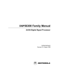
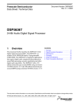
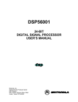
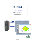
Freescale Semiconductor, Inc.
SECTION 3
MEMORY SPACES
Freescale Semiconductor, Inc...
This section is divided into two major subsections, the DSP56000 and DSP56001. Each
subsection describes the memory spaces available and the operating modes that redefine
these memory spaces.
3.1
OVERVIEW
The memory of the DSP56000/DSP56001 can be partitioned in several ways to provide
high-speed parallel operation and additional off-chip memory expansion. Program and
data memory are separate, and the data memory is, in turn, divided into two separate
memory spaces, X and Y. Both the program and data memories can be expanded offchip. There are also two on-chip data read-only memories (ROMs) that can overlay a portion of the X and Y data memories and a bootstrap ROM (DSP56001 only) that can
overlay part of the program random-access memory (RAM). The data memories are divided into two independent spaces to work with the two address arithmetic logic units
(ALUs) to feed two operands simultaneously to the data ALU.
3.2
DSP56000 MEMORY INTRODUCTION
The three independent memory spaces of the DSP56001, X data, Y data, and program,
are shown in Figure 3-1. The memory spaces are configured by control bits in the operating mode register (OMR). The operating mode control bits (MA and MB) in the OMR
control the program memory map and select the reset vector address. The data ROM enable (DE) bit in the OMR controls the X and Y data memory maps and enables/disables
the internal X and Y data ROMs. The bootstrap memory on the DSP56000 is used only
for factory testing and should not be invoked by the user.
3.2.1
X Data Memory
The on-chip X data RAM is a 24-bit-wide, internal, static memory occupying the lowest
256 locations (0–255) in X memory space. The on-chip X data ROM (factory programmed
to user specifications like the program ROM) occupies locations 256–511 in the X data
memory space and is controlled by the DE bit in the OMR. The on-chip peripheral registers occupy the top 64 locations of the X data memory ($FFC0–$FFFF). The 16-bit
addresses are received from the XAB, and 24-bit data transfers to the data ALU occur on
the XDB. The X memory may be expanded to 64K off-chip.
MOTOROLA
DSP56000/DSP56001 USER’S MANUAL
For More Information On This Product,
Go to: www.freescale.com
3-1
Freescale Semiconductor, Inc.
$FFFF
$FFFF
$FFFF
PROGRAM
MEMORY
SPACE
X DATA
MEMORY
SPACE
Y DATA
MEMORY
SPACE
$3F
INTERRUPT
VECTORS
Freescale Semiconductor, Inc...
$0
$0
$0
OPERATING MODE DETERMINES
PROGRAM MEMORY AND RESET
STARTING ADDRESS
MODE 0
MB = 0 MA = 0
$E000
EXTERNAL
$EFF
DE = 1
$FFFF ON-CHIP
$EFC0 PERIPHERALS
$FFFF
RESET
EXTERNAL
EXTERNAL
$EFF
INTERNAL
ROM
$0
MODE 3
MB = 1 MA = 1
MODE 2
MB = 1 MA = 0
$FFFF
$FFFF
DE BIT IN THE OMR DETERMINES
THE X AND Y DATA MEMORY MAPS
RESET
INTERNAL ROM
INTERNAL RESET
INTERNAL
ROM
RESET
$0
$0
INTERNAL ROM
EXTERNAL RESET
NO INTERNAL ROM
EXTERNAL RESET
EXTERNAL
PERIPHERALS
EXTERNAL
X DATA
MEMORY
EXTERNAL
Y DATA
MEMORY
$1FF INTERNAL
X ROM
INTERNAL
Y ROM
$0FF INTERNAL
X RAM
$0
INTERNAL
Y RAM
DE = 0
$FFFF ON-CHIP
$FFC0 PERIPHERALS
DATA ROMS ENABLED
EXTERNAL
PERIPHERALS
EXTERNAL
X DATA
MEMORY
EXTERNAL
Y DATA
MEMORY
$0FF INTERNAL
X RAM
$0
INTERNAL
Y RAM
DATA ROMS DISABLED
Figure 3-1 DSP56000 Memory Map
3.2.2
Y Data Memory
The on-chip Y data RAM is a 24-bit-wide, internal, static memory occupying the lowest
256 locations (0–255) in the Y memory space. The on-chip Y data ROM (factory programmed to user specifications like the program ROM) occupies locations 256–511 in Y
data memory space and is controlled by the DE bit in the OMR. The off-chip peripheral
registers should be mapped into the top 64 locations ($FFC0–$FFFF) to take advantage
of the move peripheral data (MOVEP) instruction. The 16-bit addresses are received from
the YAB, and 24-bit data transfers to the data ALU occur on the YDB. Y memory may be
3-2
DSP56000/DSP56001 USER’S MANUAL
For More Information On This Product,
Go to: www.freescale.com
MOTOROLA
Freescale Semiconductor, Inc.
expanded to 64K off-chip.
3.2.3
Program Memory
On-chip program memory consists of a 3840-location by 24-bit, high-speed ROM (3.75K
x 24) that is enabled/disabled by the MA and MB bits in the OMR. When the on-chip program memory is disabled, either off-chip memory or a special mode 1 ROM is selected
for program memory.
Freescale Semiconductor, Inc...
NOTE: The mode 1 ROM is used only for test purposes on the DSP56000 and should not
be invoked by the user.
Addresses are received from the program control logic (usually the program counter) over
the PAB. Off-chip program memory may be written using move program memory
(MOVEM) instructions. The interrupt vectors for the on-chip resources are located in the
bottom 64 locations ($0000–$003F) of program memory. Program memory may be expanded to 64K off-chip.
3.2.4
Chip Operating Modes
The DSP operating modes determine the memory maps for program and data memories
and the startup procedure when the DSP leaves the reset state. The MODA and MODB
pins are sampled as the DSP leaves the reset state, and the initial operating mode of the
DSP is set accordingly. When the reset state is exited, the MODA and MODB pins become general-purpose interrupt pins, IRQA and IRQB. One of three initial operating
modes is selected: single chip, normal expanded, or development. Chip operating modes
can be changed by writing the operating mode bits (MB, MA) in the OMR. Changing operating modes does not reset the DSP. It is desirable to disable interrupts immediately
before changing the OMR to prevent an interrupt from going to the wrong memory location. Also, one no-operation (NOP) instruction should be included after changing the OMR
to allow for remapping to occur.
Some pins on the DSP are mode independent; whereas, the use of others depends on
the particular operating mode. Specifically, external address bus, data bus, and bus conTable 3-1 Initial DSP56000 Operating Mode Summary
MOTOROLA
Operating
Mode
MOD B
MODA
0
0
0
Single-Chip Mode
1
0
1
Single-Chip Mode
2
1
0
Normal Expanded Mode
3
1
1
Development Mode
Description
DSP56000/DSP56001 USER’S MANUAL
For More Information On This Product,
Go to: www.freescale.com
3-3
Freescale Semiconductor, Inc.
trol pins are affected by the particular operating mode. Table 3-1 shows the mode
assignments.
3.2.4.1 Single-Chip Mode (Mode 0). In the single-chip mode, all internal program and data
Freescale Semiconductor, Inc...
RAM memories are enabled. A hardware reset causes the DSP to jump to internal program
memory location $0000 ($=hexadecimal notation) and resume execution. The memory map
for this mode is shown in Figure 3-2. The memory maps for mode 0 and mode 2 (see Figure
3-3) are identical. The difference between the two modes is that reset vectors to program
memory location $0000 in mode 0 and vectors to location $E000 in mode 2.
PROGRAM
MEMORY SPACE
$FFFF
X DATA
MEMORY SPACE
$FFFF
$FFC0
$FFBF
EXTERNAL
PROGRAM
MEMORY
$FFFF
ON-CHIP
PERIPHERALS
INTERNAL
PROGRAM
ROM
$01FF
$003F
INTERRUPTS
$00FF
$0000
RESET
$0000
USER-DEFINED
ROM
INTERNAL
X RAM
EXTERNAL
Y DATA
MEMORY
$01FF
DE=1
USER-DEFINED
ROM
$00FF
$0000
INTERNAL
Y RAM
ON-CHIP
PERIPHERAL MAP
INTERRUPT MAP
$0000
$FFC0
EXTERNAL
PERIPHERALS
EXTERNAL
X DATA
MEMORY
$0EFF
$007F
$0040
$003E
$003C
$003A
$0024
Y DATA
MEMORY SPACE
$FFFF
HOST COMMANDS
INTERRUPT PRIORITY
BUS CONTROL
SCI INTERFACE
SSI INTERFACE
HOST INTERFACE
PARALLEL I/0 INTERFACE
ILLEGAL INSTRUCTION INT.
TIMER INTERRUPT
HOST COMMANDS
SCI INTERRUPTS
SSI INTERRUPTS
EXTERNAL INTERRUPTS
SWI INTERRUPT
TRACE INTERRUPT
STACK ERROR INTERRUPT
RESET
$FFE0
RESERVED
$FFC0
NOTE: Addresses $FFC0–$FFFF in X data memory are NOT available externally.
Figure 3-2 Memory Map for DSP56000 Mode 0: Single-Chip Mode
3.2.4.2 Mode 1. Mode 1 is the same as Mode 0 on the DSP56000. It is recommended that
3-4
DSP56000/DSP56001 USER’S MANUAL
For More Information On This Product,
Go to: www.freescale.com
MOTOROLA
Freescale Semiconductor, Inc.
PROGRAM
MEMORY SPACE
$FFFF
$E000
X DATA
MEMORY SPACE
$FFFF
$FFC0
$FFBF
RESET
Freescale Semiconductor, Inc...
$003F
$0000
INTERNAL
PROGRAM
ROM
$FFFF
ON-CHIP
PERIPHERALS
$01FF
$017F
$00FF
INTERRUPTS
$0000
USER-DEFINED
ROM
INTERNAL
X RAM
$0000
HOST COMMANDS
EXTERNAL
Y DATA
MEMORY
$01FF
DE=1
$00FF
$0000
USER-DEFINED
ROM
INTERNAL
Y RAM
$FFFF
INTERRUPT PRIORITY
BUS CONTROL
SCI INTERFACE
SSI INTERFACE
HOST INTERFACE
PARALLEL I/0 INTERFACE
ILLEGAL INSTRUCTION INT.
TIMER INTERRUPT
HOST COMMANDS
SCI INTERRUPTS
SSI INTERRUPTS
EXTERNAL INTERRUPTS
SWI INTERRUPT
TRACE INTERRUPT
STACK ERROR INTERRUPT
RESET
EXTERNAL
PERIPHERALS
ON-CHIP
PERIPHERAL MAP
INTERRUPT MAP
$007F
$0040
$003E
$003C
$003A
$0024
$FFC0
$FFBF
EXTERNAL
X DATA
MEMORY
EXTERNAL
PROGRAM
MEMORY
$0EFF
Y DATA
MEMORY SPACE
$FFE0
RESERVED
$FFC0
NOTE: Addresses $FFC0–$FFFF in X data memory are NOT available externally.
Figure 3-3 Memory Map for DSP56000 Mode 2: Normal Expanded Mode
this mode not be invoked by the user.
3.2.4.3
Normal Expanded Mode (Mode 2). Mode 2 is almost identical to mode 0 (see
3.2.4.1 Single-Chip Mode (Mode 0). In the single-chip mode, all internal program and
data RAM memories are enabled. A hardware reset causes the DSP to jump to internal
program memory location $0000 ($=hexadecimal notation) and resume execution. The
memory map for this mode is shown in Figure 3-2. The memory maps for mode 0 and
mode 2 (see Figure 3-3) are identical. The difference between the two modes is that reset vectors to program memory location $0000 in mode 0 and vectors to location $E000
in mode 2. for further information).
3.2.4.4 Development Mode (Mode 3). The development mode is similar to the normal expanded mode except that internal program memory is disabled. All references to program
memory space are directed to external program memory, which is accessed on the external
data bus. The memory map for this mode is shown in Figure 3-4. DSP56000 chips with bad
MOTOROLA
DSP56000/DSP56001 USER’S MANUAL
For More Information On This Product,
Go to: www.freescale.com
3-5
Freescale Semiconductor, Inc.
PROGRAM
MEMORY SPACE
$FFFF
X DATA
MEMORY SPACE
$FFFF
$FFC0
$FFBF
EXTERNAL
PROGRAM
MEMORY
Y DATA
MEMORY SPACE
$FFFF
ON-CHIP
PERIPHERALS
$FFC0
$FFBF
EXTERNAL
PERIPHERALS
EXTERNAL
X DATA
MEMORY
EXTERNAL
Y DATA
MEMORY
$01FF
Freescale Semiconductor, Inc...
DE=0
$003F
INTERRUPTS
$00FF
$0000
RESET
$0000
INTERNAL
X RAM
$0000
$0000
INTERNAL
Y RAM
ON-CHIP
PERIPHERAL MAP
INTERRUPT MAP
$007F
$0040
$003E
$003C
$003A
$0024
$00FF
$FFFF
HOST COMMANDS
INTERRUPT PRIORITY
BUS CONTROL
SCI INTERFACE
SSI INTERFACE
HOST INTERFACE
PARALLEL I/0 INTERFACE
ILLEGAL INSTRUCTION INT.
TIMER INTERRUPT
HOST COMMANDS
SCI INTERRUPTS
SSI INTERRUPTS
EXTERNAL INTERRUPTS
SWI INTERRUPT
TRACE INTERRUPT
STACK ERROR INTERRUPT
RESET
$FFE0
RESERVED
$FFC0
NOTE: Addresses $FFC0–$FFFF in X data memory are NOT available externally.
Figure 3-4 Memory Map for DSP56000 Mode 3: Development Mode
or obsolete internal program ROM code can be used with external program memory in the development mode. The memory map in Figure 3-4is shown with DE arbitrarily set to zero.
3.2.5
Security ROM Version (DSP56000)1
The security ROM version of the DSP56000 is a standard DSP56000 that has been modified
to prevent unauthorized access to the program contained in the DSP program ROM. This
protection is accomplished in two ways. First, the DSP is forced into the single-chip mode
at reset. The chip powers up in single-chip mode, and it is not possible to enter any other
mode on powerup. The MODA/IRQA and MODB/IRQB pins are configured only as IRQA
and IRQB and cannot be used to change the mode. Second, the programmer must avoid
fetches from external program memory =m i.e., the user code must be placed only in internal
1. For additional information concerning this part, contact the Motorola field office.
3-6
DSP56000/DSP56001 USER’S MANUAL
For More Information On This Product,
Go to: www.freescale.com
MOTOROLA
Freescale Semiconductor, Inc.
program ROM. This placement prevents the execution of unauthorized code that might be
used to dump the contents of the program ROM.
3.3
DSP56001 MEMORY INTRODUCTION
Freescale Semiconductor, Inc...
The three independent memory spaces of the DSP56001, X data, Y data, and program, are
shown in Figure 3-5. The memory spaces are configured by control bits in the OMR. The MA
and MB control bits in the OMR control the program memory map and select the reset vector
address. The DE bit in the OMR controls the X and Y data memory maps and enables/disables
the internal X and Y data ROMs. One additional memory available on the DSP56001 is the
bootstrap memory that overlays the program memory in mode 1.
3.3.1
X Data Memory
The on-chip X data RAM is a 24-bit-wide, static, internal memory occupying the lowest 256
locations (0–255) in X memory space. The on-chip X data ROM occupies locations 256–511
in the X data memory space when enabled by setting DE to one in the OMR. The X data ROM
is factory programmed with positive Mu-law and A-law expansion tables, which are useful in
telecommunication applications. The on-chip peripheral registers occupy the top 64 locations
of the X data memory (locations $FFC0–$FFFF). The 16-bit addresses are received from the
XAB, and 24-bit data transfers to the data ALU occur on the XDB. The X memory may be expanded to 64K off-chip.
3.3.2
Y Data Memory
The on-chip Y data RAM is a 24-bit-wide, static, internal memory occupying the lowest
256 locations (0–255) in the Y memory space. The on-chip Y data ROM occupies locations 256–511 in Y data memory space when enabled by setting DE to one in the
OMR. The Y data ROM is factory programmed with a full, four-quadrant, sine-wave
table (see DSP56001 Advance Information Data Sheet(ADI1290)), which is useful for
fast Fourier transforms, discrete Fourier transforms, and waveform generation. The
off-chip peripheral registers should be mapped into the top 64 locations ($FFC0–
$FFFF) to take advantage of the MOVEP instruction. The 16-bit addresses are received from the YAB, and 24-bit data transfers to the data ALU occur on the YDB. Y
memory may be expanded to 64K off-chip.
3.3.3
Program Memory
On-chip program memory consists of a 512-location by 24-bit, high-speed, static RAM
that is enabled/disabled by the MA and MB bits in the OMR. When the on-chip program memory is disabled, either off-chip memory or a special bootstrap ROM is
selected for program memory.
MOTOROLA
DSP56000/DSP56001 USER’S MANUAL
For More Information On This Product,
Go to: www.freescale.com
3-7
Freescale Semiconductor, Inc.
$FFFF
$FFFF
$FFFF
PROGRAM
MEMORY
SPACE
X DATA
MEMORY
SPACE
Y DATA
MEMORY
SPACE
$3F
INTERRUPT
VECTORS
Freescale Semiconductor, Inc...
$0
$0
OPERATING MODE DETERMINES
PROGRAM MEMORY AND RESET
STARTING ADDRESS
MODE 0
MB = 0 MA = 0
MODE 2
MB = 1 MA = 0
$FFFF
$FFFF
$E000
EXTERNAL
$1FF
$0
INTERNAL PRAM
INTERNAL RESET
DE = 1
$FFFF ON-CHIP
$FFC0 PERIPHERALS
$FFFF
EXTERNAL
$1FF
INTERNAL
RAM
$0
EXTERNAL
PERIPHERALS
DE = 0
$FFFF ON-CHIP
$FFC0 PERIPHERALS
EXTERNAL
PERIPHERALS
RESET
$1FF
RESET
DE BIT IN THE OMR DETERMINES
THE X AND Y DATA MEMORY MAPS
MODE 3
MB = 1 MA = 1
EXTERNAL
INTERNAL
RAM
$0
$0
RESET
INTERNAL PRAM NO INTERNAL PRAM
EXTERNAL RESET EXTERNAL RESET
EXTERNAL
X DATA
MEMORY
EXTERNAL
Y DATA
MEMORY
$1FF INTERNAL
X ROM
INTERNAL
Y ROM
$0FF INTERNAL
X RAM
$0
INTERNAL
Y RAM
DATA ROMS ENABLED
EXTERNAL
X DATA
MEMORY
EXTERNAL
Y DATA
MEMORY
$0FF INTERNAL
X RAM
$0
INTERNAL
Y RAM
DATA ROMS DISABLED
Figure 3-5 DSP56001 Memory Map
Addresses are received from the program control logic (usually the program counter) over
the PAB. Program memory may be written using MOVEM instructions. The interrupt vectors for the on-chip resources are located in the bottom 64 locations ($0000–$003F) of
program memory. Program memory may be expanded to 64K off-chip.
Program RAM provides a method of developing code efficiently, and programs can be
changed dynamically, allowing efficient overlaying of DSP software algorithms. In this
way, the on-chip program RAM operates as a fixed cache, thereby minimizing contention
with accesses to external data memory spaces.
The bootstrap mode overlays the program memory in mode 1 and provides a convenient,
3-8
DSP56000/DSP56001 USER’S MANUAL
For More Information On This Product,
Go to: www.freescale.com
MOTOROLA
Freescale Semiconductor, Inc.
low-cost method of loading the DSP56001 program RAM with a program after power-on
reset. The bootstrap mode also allows loading the program RAM from a single, inexpensive EPROM through port A or via the host interface using a host processor.
Freescale Semiconductor, Inc...
3.3.4
Bootstrap ROM (DSP56001 Only)
Factory programmed to perform the bootstrap operation from the memory expansion port
(port A) or from the host interface, the 32-word on-chip ROM is invoked while the processor is in operating mode 1. Users have no access to the bootstrap ROM other than
through the bootstrap process.
3.3.5
Chip Operating Modes
The DSP operating modes determine the memory maps for program and data memories
and the startup procedure when the DSP leaves the reset state. The MODA and MODB
pins are sampled as the DSP leaves the reset state, and the initial operating mode of the
DSP is set accordingly. When the reset state is exited, the MODA and MODB pins become general-purpose interrupt pins, IRQA and IRQB. One of four initial operating modes
is selected: single chip, special bootstrap, normal expanded, or development. Chip operating modes can be changed by writing the operating mode bits (MB, MA) in the OMR.
Changing operating modes does not reset the DSP. It is desirable to disable interrupts immediately before changing the OMR to prevent an interrupt from going to the wrong
memory location. For example, if the user changed to the bootstrap mode and an interrupt
occurred, he would execute the bootstrap code out of order. Also, one NOP instruction
must be included after changing the OMR to allow for remapping to occur.
Some pins on the DSP are mode independent; whereas, others depend on the particular
operating mode. Specifically, external address bus, data bus, and bus control pins are affected by the particular operating mode. Table 3-2 depicts the mode assignments.
Table 3-2 Initial DSP56001 Operating Mode Summary
Operating
Mode
MODB
MODA
0
0
0
Single-Chip Mode
1
0
1
Special Bootstrap Mode
2
1
0
Normal Expanded Mode
3
1
1
Development Mode
Description
3.3.5.1 Single-Chip Mode (Mode 0)
In the single-chip mode, all internal program and data RAM memories are enabled. A
hardware reset causes the DSP to jump to internal program memory location $0000 and
MOTOROLA
DSP56000/DSP56001 USER’S MANUAL
For More Information On This Product,
Go to: www.freescale.com
3-9
Freescale Semiconductor, Inc.
PROGRAM
MEMORY SPACE
$FFFF
X DATA
MEMORY SPACE
$FFFF
$FFC0
$FFBF
EXTERNAL
PROGRAM
MEMORY
Freescale Semiconductor, Inc...
$FFFF
ON-CHIP
PERIPHERALS
INTERNAL
PROGRAM
RAM
$01FF
$003F
INTERRUPTS
$00FF
$0000
RESET
$0000
INTERNAL
X ROM
INTERNAL
X RAM
EXTERNAL
Y DATA
MEMORY
$01FF
DE=1
$00FF
$0000
INTERNAL
Y ROM
INTERNAL
Y RAM
ON-CHIP
PERIPHERAL MAP
INTERRUPT MAP
$0000
$FFC0
EXTERNAL
PERIPHERALS
EXTERNAL
X DATA
MEMORY
$01FF
$007F
$0040
$003E
$003C
$003A
$0024
Y DATA
MEMORY SPACE
$FFFF
HOST COMMANDS
INTERRUPT PRIORITY
BUS CONTROL
SCI INTERFACE
SSI INTERFACE
HOST INTERFACE
PARALLEL I/0 INTERFACE
ILLEGAL INSTRUCTION INT.
TIMER INTERRUPT
HOST COMMANDS
SCI INTERRUPTS
SSI INTERRUPTS
EXTERNAL INTERRUPTS
SWI INTERRUPT
TRACE INTERRUPT
STACK ERROR INTERRUPT
RESET
$FFE0
RESERVED
$FFC0
NOTE: Addresses $FFC0–$FFFF in X data memory are NOT available externally.
Figure 3-6 Memory Map for DSP56001 Mode 0: Single-Chip
resume execution. The memory map for this mode is shown in Figure 3-6. The memory maps for mode 0 and mode 2 (see Figure 3-7) are identical. The difference
between the two modes is that reset vectors to program memory location $0000 in
mode 0 and vectors to location $E000 in mode 2.
3.3.5.2 Special Bootstrap Mode (Mode 1)
The bootstrap mode is a special mode that loads internal program RAM either from a
byte-wide external memory such as EPROM or from the host interface. After loading
the internal memory, the DSP switches to the single-chip mode and begins program
execution at on-chip program memory location $0000.
One method of selecting mode 1 is to assert the reset pin on the DSP56001. When the DSP
leaves the reset state (RESET goes high), the MODB and MODA pins are sampled (they
should be set to zero and one, respectively), and the initial operating mode of the DSP is
set accordingly. The following actions occur once the processor comes out of the reset state.
3 - 10
DSP56000/DSP56001 USER’S MANUAL
For More Information On This Product,
Go to: www.freescale.com
MOTOROLA
Freescale Semiconductor, Inc.
PROGRAM
MEMORY SPACE
$FFFF
$E000
X DATA
MEMORY SPACE
$FFFF
RESET
$FFC0
$FFBF
EXTERNAL
PROGRAM
MEMORY
$01FF
$FFFF
ON-CHIP
PERIPHERALS
$017F
+A-LAW/LIN
Freescale Semiconductor, Inc...
INTERRUPTS
$0000
HOST COMMANDS
$01FF
FULL
SINE-WAVE
TABLE
$00FF
INTERNAL
X RAM
$0000
INTERNAL
Y RAM
$0000
ON-CHIP
PERIPHERAL MAP
$FFFF
INTERRUPT PRIORITY
BUS CONTROL
SCI INTERFACE
SSI INTERFACE
HOST INTERFACE
PARALLEL I/0 INTERFACE
ILLEGAL INSTRUCTION INT.
TIMER INTERRUPT
HOST COMMANDS
SCI INTERRUPTS
SSI INTERRUPTS
EXTERNAL INTERRUPTS
SWI INTERRUPT
TRACE INTERRUPT
STACK ERROR INTERRUPT
RESET
EXTERNAL
Y DATA
MEMORY
+MU-LAW/LIN
INTERRUPT MAP
$007F
$0040
$003E
$003C
$003A
$0024
$FFC0
$FFBF
DE=1
$00FF
$003F
$0000
EXTERNAL
PERIPHERALS
EXTERNAL
X DATA
MEMORY
$01FF
PROGRAM
RAM
Y DATA
MEMORY SPACE
$FFE0
RESERVED
$FFC0
NOTE: Addresses $FFC0–$FFFF in X data memory are NOT available externally.
Figure 3-7 Memory Map for DSP56001 Mode 2: Normal Expanded Mode
1. The control logic maps the bootstrap ROM into the internal DSP program memory
space starting at location $0000.
2. The control logic causes program reads to come from the bootstrap ROM (only address bits 4–0 are significant) and all writes go to the program RAM (all address bits
are significant). This condition allows the bootstrap program to load the user program from $0000–$01FF.
3. Program execution begins at location $0000 in the bootstrap ROM. The bootstrap
ROM program can load program RAM through either the memory expansion port or
through the host interface. The choice is made by looking at bit 23 of P:$C000. The
processor loads from the host interface if bit 23 is a zero; if bit 23 is a one, it loads
from a byte-wide memory starting at P:$C000.
4. The bootstrap ROM program executes the following sequence to end the bootstrap
operation and begin executing the user program. First, operating mode 2 is entered
by writing to the OMR. This action will be timed to remove the bootstrap ROM from
the program memory map and re-enable read/write access to the program RAM.
MOTOROLA
DSP56000/DSP56001 USER’S MANUAL
For More Information On This Product,
Go to: www.freescale.com
3 - 11
Freescale Semiconductor, Inc.
Second, the change to mode 2 is exactly timed to allow the bootstrap program to execute a single-cycle instruction (clear status register), then a JMP #<00, and begin
execution of the user program at location $0000.
The bootstrap mode may also be selected by writing zero to MB and one to MA in the OMR. This
selection initiates a timed operation to map the bootstrap ROM into the program address space
after a delay to allow execution of a single-cycle instruction and then a JMP #<00 to begin the
bootstrap process previously described. This technique allows the DSP56001 user to reboot the
system (with a different program, if desired). The code to enter the bootstrap mode is as follows:
Freescale Semiconductor, Inc...
MOVEP
MOVEC
#0,X:$FFFF
#1,OMR
;Disable interrupts.
;The bootstrap ROM is mapped ;into
the lowest 32 locations
;in program memory.
NOP
;Allow one cycle delay for the
;remapping.
JMP
<$0
;Begin bootstrap.
The interrupts are disabled before executing the bootstrap code; otherwise, an interrupt
could cause the DSP to execute the bootstrap code out of sequence because the bootstrap program overlays the interrupt vectors.
The bootstrap ROM contains the bootstrap firmware program that performs initial loading
of the DSP56001 program RAM.
Written in DSP56001 assembly language, the program contains two separate methods of
initializing the program RAM: loading from a byte-wide memory starting at location
P:$C000 or loading through the host interface. The particular method used is selected by
the level of program memory location P:$C000 bit 23.
If location P:$C000 bit 23 is read as a one, the external bus version of the bootstrap program will be selected. Typically, a byte-wide EPROM will be connected to the DSP56001
address and data bus. The data contents of the EPROM must be organized as shown in
3 - 12
DSP56000/DSP56001 USER’S MANUAL
For More Information On This Product,
Go to: www.freescale.com
MOTOROLA
Freescale Semiconductor, Inc.
Table 3-3:
Table 3-3 Organization of EPROM Data Contents
Freescale Semiconductor, Inc...
Address of External
Byte-Wide Memory:
Contents Loaded to Internal
Program RAM at:
P:$C000
P:$0000
low byte
P:$C001
P:$0000
mid byte
P:$C002
P:$0000
high byte
•
•
•
•
•
•
P:$C5FD
P:$01FF
low byte
P:$C5FE
P:$01FF
mid byte
P:$C5FF
P:$01FF
high byte
If location P:$C000 bit 23 is read as a zero, the host interface version of the bootstrap program will be selected. Typically, a host microprocessor will be connected to the DSP56001 host interface. The host microprocessor must write the host interface bytewide registers TXH, TXM, and then TXL with the desired contents of program RAM from location P:$0000 up to P:$01FF. If less than 512 words are to be loaded, the host programmer can exit the bootstrap program and force the DSP56001 to begin executing
at location P:$0000 by setting HF0 to one in the host interface control register. In most systems, the DSP56001 response is so fast that handshaking between the DSP56001 and the host is not necessary.
3.3.5.3 Normal Expanded Mode (Mode 2)
Mode 2 is almost identical to mode 0 (see 3.3.5.1 Single-Chip Mode (Mode 0) for
details).
MOTOROLA
DSP56000/DSP56001 USER’S MANUAL
For More Information On This Product,
Go to: www.freescale.com
3 - 13
Freescale Semiconductor, Inc.
3.3.5.4 Development Mode (Mode 3). The development mode is similar to the normal expanded mode except that internal program memory is disabled. All references to program memory
space are directed to external program memory, which is accessed on the external data bus. The
reset vector points to location $0000. The memory map for this mode is shown in Figure 3-8. The
memory map in Figure 3-8 is shown with DE arbitrarily set to zero.
Freescale Semiconductor, Inc...
PROGRAM
MEMORY SPACE
$FFFF
X DATA
MEMORY SPACE
$FFFF
$FFC0
$FFBF
EXTERNAL
PROGRAM
MEMORY
Y DATA
MEMORY SPACE
$FFFF
ON-CHIP
PERIPHERALS
EXTERNAL
PERIPHERALS
$FFC0
$FFBF
EXTERNAL
X DATA
MEMORY
EXTERNAL
Y DATA
MEMORY
$01FF
DE=0
$003F
INTERRUPTS
$00FF
$0000
RESET
$0000
INTERNAL
X RAM
$0000
$0000
INTERNAL
Y RAM
ON-CHIP
PERIPHERAL MAP
INTERRUPT MAP
$007F
$0040
$003E
$003C
$003A
$0024
$00FF
$FFFF
HOST COMMANDS
INTERRUPT PRIORITY
BUS CONTROL
SCI INTERFACE
SSI INTERFACE
HOST INTERFACE
PARALLEL I/0 INTERFACE
ILLEGAL INSTRUCTION INT.
TIMER INTERRUPT
HOST COMMANDS
SCI INTERRUPTS
SSI INTERRUPTS
EXTERNAL INTERRUPTS
SWI INTERRUPT
TRACE INTERRUPT
STACK ERROR INTERRUPT
RESET
$FFE0
RESERVED
$FFC0
NOTE: Addresses $FFC0–$FFFF in X data memory are NOT available externally.
Figure 3-8 Memory Map for DSP56001 Mode 3: Development Mode
3 - 14
DSP56000/DSP56001 USER’S MANUAL
For More Information On This Product,
Go to: www.freescale.com
MOTOROLA