1
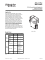
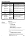
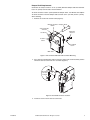
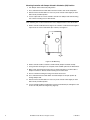
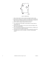
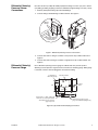
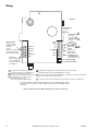
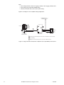
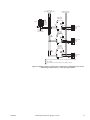
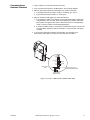
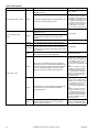
MNL-V1RVx
MNL-V2RVx
TAC I/A Series MicroNet Variable Air
Volume Controllers
Installation Instructions
Application
TAC I/A Series© MicroNet MNL-V1RVx and MNLV2RVx VAV Controllers are interoperable variable air
volume controllers designed in accordance with
LONMARK®-guidelines. These controllers provide
pressure independent control for cooling and reheat
applications. They feature a built-in actuator with overthe-shaft damper mounting, an integral velocity
pressure transducer, LED indication, support for an
MN-Sx digital sensor, push-button manual override,
mechanical position indication, and an easy-to-set
mechanical travel limit. They function in standalone
mode or as part of a MicroNet LonWorks® network
using the integral FT 3150® Free Topology
communications transceiver. A direct connection to a
WPA-LON Work Place Communication adapter and a
PC with Work Place Tech Tool software is necessary to
download and modify applications.
SW
2
SW 4H3
24
SW H2
24H
24H 1
24G
GN
D
S-L
A
CO O
M
UI
K/C DI
OM
S-L
K
LO
N
LO
N
MNL-V2RVx
Model Chart
MNL-V1RVxa
MNL-V2RVxa
Digital Inputs
1
1
Digital
Outputs
0
3
Universal
Inputs
1
1
Analog
Outputs
0
1
Model
Inputs/
Outputs
Box
Configuration
Cooling
•
•
•
•
•
Cooling
Series Fan
Induction
Parallel Fan
None
Reheat Type
None
• Staged Electric
• Time
Proportioned
• Floating/
Proportional
Hydronic Reheat
• None
Other
None
• Occupancy
• Satellite
Control
Strategies
a
Vx denotes LONMARK VAV (Variable Air Volume) profile and profile version
number.
Printed in U.S.A.
02-10
© 2010 Schneider Electric. All rights reserved.
F-26282-6
Applicable Documentation
F-Number
Description
Audience
Purpose
F-26277
TAC I/A Series MicroNet
MN-Sx Series Sensors
General Instructions
–
–
–
–
Application Engineers
Installers
Service Personnel
Start-up Technicians
Provides step-by-step installation and checkout procedures for
TAC I/A Series MicroNet MN-Sx Series Sensors. Also contains
instructions for sensor operation.
F-26303
TAC I/A Series MicroNet
System Overview
–
–
–
–
Application engineers
Installers
Start-up technicians
Service personnel
Provides an overview of the TAC I/A Series MicroNet System. It
includes brief descriptions of the hardware and software
components, and how they may be combined to create MicroNet
networks and stand-alone systems.
F-27254
Work Place Tech Tool 4.0
Engineering Guide
–
–
–
–
Application Engineers
Installers
Service Personnel
Start-up Technicians
Provides engineering and technical information for applying and
using all aspects of Work Place Tech Tool.
F-26507
TAC I/A Series MicroNet
Systems Engineering
Guide
–
–
–
–
Application Engineers
Installers
Service Personnel
Start-up Technicians
Provides engineering and technical information to assist in
designing a complete MicroNet controller system using different
architectures, components, and software.
F-27255
Work Place Tech Tool 4.0
User’s Guide
–
–
–
–
Application Engineers
Installers
Service Personnel
Start-up Technicians
Provides step-by-step instructions for using Work Place Tech Tool.
F-26363
EN-206 Guidelines for
Powering Multiple FullWave and Half-Wave
Rectifier Devices from a
Common Transformer
– Application Engineers
– Installers
– Service Personnel
Offers guidelines for avoiding equipment damage associated with
improperly wiring devices of varying rectifier types. Contains
instructions for identifying device rectifier type, guidelines for
correctly powering devices of varying rectifier types, and examples
illustrating proper power wiring techniques.
F-26421
MicroNet VAV Flow
Balance User’s Manual
–
–
–
–
Provides step-by-step instructions for using the MicroNet VAV
Flow Balance software.
Application Engineers
Installers
Service Personnel
Start-up Technicians
Installation
Inspection
Requirements
(These items not provided)
Inspect carton for damage. If damaged, notify carrier immediately. Inspect controllers for
damage upon receipt.
• Installer must be a qualified technician
• Job wiring diagrams
• Tools:
–
–
–
–
–
–
–
1/8" allen wrench or hex driver
1/4 inch hex driver for travel adjustment screws
Pliers for turning damper shafts
Digital Volt-ohm meter (DVM)
Drill and bits for mounting screw
Static protection wrist strap
Torque wrench (capable of measuring at least 70 in-lb (7.9 N-m))
• MNA-FLO-1 enclosure for connecting to conduit (optional)
• AM-135, 3/8 in. (9.5mm) to 1/2 in. (12.8mm) shaft adapter (optional)
• Class 2 power transformer supplying a nominal 24 Vac (20.4 to 30 Vac) with a minimum
rating of 12 VA, 50/60 Hz per controller plus Digital Output (DO) loads. Each DO can be
up to 24 VA. In European Community, transformer must conform to EN 60742
• Terminators:
– One LON-TERM1 terminator required for each free topology
– Two LON-TERM2 terminators required for each bus topology
• One #10 sheet metal screw
• 0.170 in.(17/100) I.D. FRPE polyethylene tubing or 0.125 in. (1/8) I.D. or 0.25 in. (1/4)
O.D. tygon tubing for piping connections. Not more than five feet (1.52m) long.
2
© 2010 Schneider Electric. All rights reserved.
F-26282-6
Precautions
General
Warning: Electrical shock hazard! Disconnect power before installing or removing the
cover.
• Follow Static precautions when installing this equipment.
• Use copper conductors that are suitable for 167°F (75°C).
• Make all connections according to electrical wiring diagram, national and local electrical
codes.
Static Precautions
Static charges damage electronic components. The microprocessor and associated circuitry
are extremely sensitive to static discharge. Use the following precautions when installing,
servicing, or operating the system.
• Work in a static-free area.
• Discharge static electricity by touching a known, securely grounded object.
• Use a wrist strap connected to earth ground when handling the controller’s printed
circuit board.
Federal Communications Commission (FCC)
This equipment has been tested and found to comply with the limits for a Class B digital
device, pursuant to Part 15 of the FCC Rules. These limits are designed to provide
reasonable protection against harmful interference in residential installations. This
equipment generates, uses, and can radiate radio frequency energy and may cause harmful
interference if not installed and used in accordance with the instructions. Even when
instructions are followed, there is no guarantee that interference will not occur in a particular
installation. If this equipment causes harmful interference to radio or television reception—
which can be determined by turning the equipment off and on—the user is encouraged to
try to correct the interference by one or more of the following measures:
• Reorient or relocate the receiving antenna.
• Increase the separation between the equipment and receiver.
• Connect the equipment to an outlet on a circuit different from that to which the receiver
is connected.
• Consult the dealer or an experienced radio/television technician for help.
Canadian Department of Communications (DOC)
This class B digital apparatus meets all requirements of the Canadian Interference-Causing
Equipment Regulations.
European Community Directives
This equipment meets all requirements of European Community Directives for Low Voltage
(72/23/EEC), General Safety (92/59/EEC), and Electromagnetic Compatibility
(89/336/EEC).
F-26282-6
© 2010 Schneider Electric. All rights reserved.
3
Location
These controllers are for indoor use only.
Caution:
• Avoid locations where excessive moisture, corrosive fumes, vibration, or explosive
vapors are present.
• Avoid electrical noise interference. Do not install near large contactors, electrical
machinery, or welding equipment.
• Locate where ambient temperatures do not exceed 131°F (55°C) or fall below 32°F
(0°C) and relative humidity does not exceed 85% or fall below 5%, non-condensing.
Mounting location must clear the maximum dimensions of the controller case and allow the
controller to be mounted flush to the surface of the terminal box and perpendicular to the
damper shaft.
Mounting
Mount controllers directly over the damper shaft in any direction and on any plane that is
perpendicular to the damper shaft. Mounting dimensions are shown in Figure-1.
Some terminal boxes have sheet metal screw heads or other protrusions near the damper
shaft. In these cases, a spacer or shim may be added under the mounting tab of the actuator
to make the actuator perpendicular to the shaft.
6-1/4
(159)
2-1/2
(63)
4-1/2
(114)
1 3/4
(44)
7-3/4
(197)
5-3/4
(146)
Dimensions shown
are in inches (mm).
Figure-1 Mounting Dimensions.
4
© 2010 Schneider Electric. All rights reserved.
F-26282-6
Damper Shaft Requirements
Controllers are ready to mount on 1/2 in. (12.8 mm) diameter damper shafts that extend at
least 2 in. (51mm) from the side of the terminal box.
To mount controller on 3/8 in. (9.5mm) diameter damper shafts, use AM-135 shaft adapter.
To mount controller on shorter damper shafts, between 3/4 in. (19.1mm) and 2 in. (51mm),
do the following:
1. Remove set screws from actuator collar (Figure-2).
Manual Override Damper Shaft
Button
VAV Controller
Actuator
Mounting
Bracket
Set Srews
Actuator
Collar
SW
2
SW 4H3
24
SW H2
24
24H H1
24G
GN
D
Sheet Metal
Screw
A
CO O
M
UI
K/C DI
OM
S-L
MNL-V2R
S-L
K
LO
N
LO
N
Figure-2 TAC I/A Series MicroNet VAV Controller Mounting.
2. Press manual override button and turn actuator collar to full counterclockwise position
until short shaft set screw holes are accessible (Figure-3).
Short shaft
set screw
locations
AO
M
CO I
U
DI
3
24H
SW 4H2
2
SW 1
24H
SW
OM
K/C
S-L S-LK
N
LO
N
LO
24H
24G
D
GN
Figure-3 Short Shaft Set Screw Location.
3. Install set screws in short shaft set screw holes.
F-26282-6
© 2010 Schneider Electric. All rights reserved.
5
Mounting Controller with Damper Closed in Clockwise (CW) Position
1. Turn damper shaft to full closed (CW) position.
2. Press and hold manual override button and turn actuator collar to full CW position.
3. Release manual override button. If necessary, rotate actuator collar slightly to return
button to fully extended position.
4. Loosen output shaft set screws and slide controller over damper shaft until mounting
foot contacts mounting area on VAV terminal.
Note: Mounting foot can be moved from the factory shipped location to the side location.
5. Rotate controller CCW about three degrees off centerline of VAV terminal and tighten
output shaft set screws to 60-70 in-lb (6.8-7.9 N-m). See Figure-4.
3˚
Figure-4 CW Mounting.
6. Rotate controller CCW to centerline of VAV terminal (damper should be sealed).
7. Using controller mounting foot as a template, mark and drill a pilot hole in VAV terminal.
8. Make certain mounting hole position does not affect performance of terminal box. If
damper movement is affected, install mounting foot in side location.
9. Secure controller mounting foot using a #10 sheet metal screw.
10. Press and hold manual override button and rotate damper to full open position by
turning damper shaft.
11. Release manual override button. If necessary, rotate actuator collar slightly to return
button to fully extended position.
12. Loosen and slide CCW travel adjustment screw to travel indicator pin, and tighten screw
to 28 to 32 in-lb (0.32 to 0.37 Kg-meter) (Figure-5).
6
© 2010 Schneider Electric. All rights reserved.
F-26282-6
CCW travel
adjustment screw
Damper
shaft
Manual override
button
Travel
indicator
CW travel
adjustment screw
Figure-5 Travel Adjustment.
13. Verify damper moves freely between full open and full closed positions. There must be
no binding between the actuator and damper, or obstructions hindering damper
operation.
Mounting Controller with Damper Closed in Counter-Clockwise (CCW)
Position
Note: The default setting for actuator rotation is CW Closes [0]. To reverse rotation, change
to CW Opens [100].
1. If direction of actuator rotation needs to be changed, then do (a.) through (e.) below. If not
go to Step 2.
a. Using Work Place Tech Tool, Open the project.
b. Select controller from network definition page.
c. Change “VAV Box Direction” property from CW Closes [0] to CW Opens [100].
d. Save and download changes.
e. Close Work Place Tech Tool.
2. Turn damper shaft to full closed (CCW) position.
3. Press and hold manual override button and turn actuator collar to full CCW position.
4. Release manual override button. If necessary, rotate actuator collar slightly to return
button to fully extended position.
5. Loosen output shaft setscrew and slide controller over damper shaft until mounting foot
contacts mounting area on VAV terminal.
Note: Mounting foot can be moved from the factory shipped location to side location.
6. Rotate controller Clockwise (CW) about three degrees off centerline of VAV terminal
and tighten output shaft set screws to 60-70 in-lb (6.8-7.9 N-m). See Figure-6.
F-26282-6
© 2010 Schneider Electric. All rights reserved.
7
3˚
Figure-6 CCW Mounting.
7. Rotate controller CCW to centerline of VAV terminal (damper should be sealed).
8. Using controller mounting foot as a template, mark and drill a pilot hole in VAV terminal.
9. Make certain the mounting hole position does not affect performance of terminal box. If
damper movement is affected, install mounting foot in side location.
10. Secure controller mounting foot using a #10 sheet metal screw.
11. Press and hold manual override button and rotate damper to full open position by
turning damper shaft.
12. Release manual override button. If necessary, rotate actuator collar slightly to return
button to fully extended position.
13. Loosen and slide CW travel adjustment screw to travel indicator pin, and tighten screw
to 28 to 32 in-lb (0.32 to 0.37 Kg-meter) (Figure-5).
14. Verify damper moves freely between full open and full closed positions. There must be
no binding between the actuator and damper, or obstructions hindering damper
operation.
8
© 2010 Schneider Electric. All rights reserved.
F-26282-6
Differential (Velocity)
Pressure Sensor
Connections
Use either 0.170 in.(17/100) I.D. FRPE polyethylene tubing or 0.125 in.(1/8) I.D. or 0.25 in.
(1/4) O.D. tygon tubing for piping connections. Maximum length of tubing is five feet (1.52 m).
1. Remove yellow plastic fitting caps from barbed fittings.
2. Connect tubing to barbed fittings on VAV Controller. See Figure-7.
Barbed
Fittings
Differential (Velocity)
Pressure Sensor
Connections
AO
M
CO I
U
DI
OM
K/C
S-L S-LK
N
LO
N
LO
3
24H
SW 4H2
2
SW 1
24H
SW
24H
24G
D
GN
Figure-7 Differential (Velocity) Pressure Connections.
3. Connect tube from P1 fitting on controller to low pressure tap on VAV terminal. See
Figure-8.
4. Connect tube from P2 fitting on controller to high pressure tap on VAV terminal. See
Figure-8.
Differential (Velocity)
Pressure Gauge
Use a differential (velocity) pressure gauge to calibrate and verify central system is
delivering accurate pressure. Figure-8 shows connections for attaching gauge. When gauge
is removed, restrictors must be plugged or removed from tubing.
Terminal Flow
Measuring Pickup
Inlet
VAV Air Terminal
HI LO
P1
P2
Air
Flow
Discharge
Duct
(LO) (HI)
AT-532-222-1-1, .0075" (190.5 µm)
Restrictors are only required when
differential (velocity) pressure
gauge is present.
HI
LO
Differential (velocity) pressure
gauge for Calibration (Magnehelic).
Figure-8 Typical VAV Terminal Piping Connections.
F-26282-6
© 2010 Schneider Electric. All rights reserved.
9
Wiring
LONWORKS
Analog Output
0 to 20mA
into an
80 to 550Ω
3
load
Universal Input
Digital Outputs
24 VA per output
at 24 Vac, Class 2.
Pilot Duty
Form A
Single Pole, Single Throw
Normally Open Relay
(switched 24H outputs)
AC Power
24 Vac, 50/60 Hz
Class 2 (EN 60742)
12 VA per controller
plus DO load
SW24H3*
SW24H2*
SW24H1*
24H
24G(COM)
GND
AO*
COM
UI
DI
S-LK/COM
S-LK
LON
LON
0 to 5 Vdc
0 to 20 mA 4
10K Thermistor 5
1K Balco
1K Platinum
Digital 1 2
Digital Input
Dry Contact 1 6
S-Link
Supports one
TAC I/A Series
MN-SX Sensor
LONWORKS Network
Communications
FT 3150 Transceiver
Controller LEDs
Service Pin Button
4 In applications requiring universal inputs with ranges of 0 to 20 mA,
1 To detect a closed switch, maximum
a 250 ohms shunt resistor kit, AD-8969-202, is needed.
resistance must be less than 300 ohms.
2 To detect an open switch, minimum
resistance must be greater than 1.5K ohms. 5 An 11K ohms shunt resistor kit, AD-8969-206, is required for a 10K ohms Thermistor
Sensor (non-850 series) universal inputs.
3 Input signals of 1 to 11 Vdc must be
converted to 0.45 to 5 Vdc
6 To detect an open switch, minimum resistance must be greater than 100K ohms.
with a voltage divider, AD-8961-220.
* The asterisk indicates that the termination appears only on the MNL-V2RVx Controller.
All other terminations appear on both the MNL-V1RVx Controller and the MNL-V2RVx
Controller.
Figure-9 MNL-V1RVx and MNL-V2RVx Series Terminal Connections.
10
© 2010 Schneider Electric. All rights reserved.
F-26282-6
The following electrical connections can be made to TAC I/A Series MicroNet VAV
controllers:
• Sensor Link (S-Link) connection to an TAC I/A Series MicroNet Sensor (MN-SX)
• MicroNet LONWORKS network (LON) connection to a MicroNet Interface (MI) and other
MicroNet controllers
• LONWORKS network connection from controller to an TAC I/A Series MicroNet Sensor
• I/O connections including:
–
–
–
–
One Universal Input (UI)
One Digital Input (DI)
One Analog Output (AO) (MNL-V2RVx model only)
Three Digital Outputs (DO) (MNL-V2RVx model only)
• Power connection to a 24 Vac nominal Class 2 (EN 60742) power source and earth
ground.
Communications Wiring
Caution:
• Communication wire pairs must be dedicated to S-Link and MicroNet LONWORKS
network (LON) communications. They cannot be part of an active, bundled telephone
trunk.
• Shielded cable is not required for S-Link or LON wiring.
• If the cable is installed in areas of high RFI/EMI, the cable must be in conduit.
• If shielded wire is used, the shield must be connected to earth ground at only one end
by a 470K ohm 1/4 watt resistor. Shield must be continuous from one end of the trunk
to the other.
Communications wiring includes a connection between the controller and an TAC I/A Series
MicroNet Sensor via the S-Link and a connection between the controller and the MicroNet
LONWORKS Network (LON). An optional LONWORKS Network connection between the
controller and one TAC I/A Series MicroNet Sensor is also possible. Figure-9 shows S-Link
and LON wiring terminations.
Sensor Link (S-Link) Wiring
S-Link wiring powers and enables the MN-Sx sensor. The S-Link needs at least 24 gage
(0.51mm), twisted pair, voice grade telephone wire. The capacitance between conductors
cannot be more than 32 pF per foot (0.3m). If shielded cable is used, the capacitance
between any one conductor and the others, connected to the shield, cannot be more than
60 pF per foot (0.3m). Maximum wire length is 200 ft. (61m).
Note:
• Controller supports one TAC I/A Series MicroNet Sensor (MN-Sx).
• S-Link wiring is polarity insensitive.
• If conduit is used between an TAC I/A Series Sensor and a controller, the MicroNet
LONWORKS network and S-Link wiring can be in the same conduit, however, they must
be separate cables. S-Link wiring can be in the same conduit with UI, AO, and DI Wiring.
MicroNet LONWORKS Network (LON) Wiring
An approved Category 4 or 5 twisted-pair cable may be used for both S-Link and optional
LONWORKS network connections between the controller and MN-Sx sensor. LONWORKS
network wiring is polarity insensitive.
Caution: Do not mix with UI, AO, DO, DI, or power types of wiring. If conduit is used
between an TAC I/A Series Sensor and a controller, LONWORKS network wiring and S-Link
wiring can be in the same conduit, however, they must be separate cables.
F-26282-6
© 2010 Schneider Electric. All rights reserved.
11
TAC I/A Series MicroNet VAV controllers use a LONWORKS Free Topology Transceiver (FT
3150) and support polarity insensitive bus (daisy-chain) and free (all combinations of star,
tee, and loop) wiring topologies. A maximum of 62 nodes can be connected per segment.
See TAC I/A Series MicroNet System Engineering Guide, F-26507 to design a MicroNet
LONWORKS TP/FT-10 network, including recommended topologies and approved cable
types.
60 pF per foot (0.3m). Maximum wire length is 200 ft. (61m).
Note:
• Use of the LON terminals to connect to the MN-Sx sensor permits the use of the
sensor’s built-in LON jack.
• To preserve the integrity of the network, the LON wiring connecting an TAC I/A Series
MicroNet controller to an MN-Sx sensor must be run to the sensor and back, in daisychain fashion. A wire “spur” must not be used to connect the sensor to the controller..
• While the MN-Sx sensor is not counted as a “node” in the LONWORKS network (LON),
all LON wiring to the sensor must be counted when determining the length of the FTT
wiring segment.
I/O Wiring
I/O connections include universal input, digital input, analog output, and digital (relay)
outputs. See Figure-9 for wire terminal information.
Caution: If shielded cable is used, connect only one end of the shield to earth ground at
controller.
Universal Input (UI), Digital Input (DI), and Analog Output (AO)
Caution:
• Input and output devices cannot share common wiring. Each connected device requires
a separate signal and return conductor.
• Power wiring cannot share conduit with UI, AO, S-Link, LON, or DI wiring.
Note:
• If maximum closed switch voltage is not more than 1.0 V and minimum open switch
voltage is at least 4.5 V, then solid state switches may be used for a UI or a DI.
• UI, AO, DI, and S-Link wiring can share a single conduit.
UI, AO, DI, wiring needs at least 24 gage (0.51mm), twisted pair, voice grade telephone wire.
The capacitance between conductors cannot be more than 32 pF per foot (0.3m). If shielded
cable is used, the capacitance between any one conductor and the others, connected to the
shield, cannot be more than 60 pF per foot (0.3m). Table-1 provides wiring specifications.
Table-1 UI, AO, and DI Wiring Specifications.
Connection
UI, AO, and DI
Gage
AWG (mm)
Maximum Distance
ft. (m)
18 (1.02)
300 (91)
20 (.81)
200 (61)
22 (.65)
125 (38)
24 (.51)
75 (23)
Digital Outputs (DO) (MNL-V2RVX only)
Caution:
• DO terminals accept one 16 gage (1.29mm) wire or two 18 gage (1.02mm) wires. The
selected wire gage must be consistent with the load current rating.
• DO wiring cannot be intermixed with DI, UI, AO, S-Link, or LON wiring.
• TAC I/A Series MicroNet VAV controllers are Class 2 (EN 60742) only devices.
12
© 2010 Schneider Electric. All rights reserved.
F-26282-6
Note:
• Digital Output wiring can be intermixed with power wiring.
• The minimum permissible load for Digital Outputs is 10mA at 5 Vdc.
Three relay outputs on the controller are used for pilot duty control of electrical contactors
and floating or two-position reheat actuators. See Figure-10. Digital output load
specifications for the controller are shown in Table-2.
1
AC Load
SW24H3
AC Load
SW24H2
AC Load
3
SW24H1
24H
Primary
Frame
24 Vac
2
24G (COM)
Class 2
Transformer
1
2
3
GND
See application documentation for
output designation and wiring specifics.
Polarity must be maintained (24H connected
to 24H and 24G connected to 24G).
Dashed lines represent internal controller
circuitry.
Figure-10 Relay Output Field Wiring.
Table-2 Relay Output Load Specifications.
Specification
Value
Maximum Relay Contact Switched Output Voltage
voltage at 24H
terminala
Maximum Output Load @ 24 Vac, Pilot Duty
24 VA
Minimum Controllable Load
10.0 mA
Maximum Off-state Leakage Current
3.5 mA
Minimum Relay Cycles at Rated Load (Power Factor = 0.4)
300,000 cycles
a
Switched output voltage is equivalent to value of input voltage.
Power Supply Wiring
Caution:
• This product contains a non-isolated half-wave rectifier power supply and must not be
powered by transformers used to power other devices containing non-isolated full-wave
rectifier power supplies. Refer to EN-206, Guidelines for Powering Multiple Full-Wave
and Half-Wave Rectifier Devices from a Common Transformer, F-26363, for detailed
information.
• Power wiring cannot be intermixed with LON, S-Link, UI, AO, or DI wiring.
• Use a Class 2 (EN 60742) power transformer supplying a nominal 24 Vac (20.4 to 30
Vac) with a minimum rating of 12 VA at 50/60 Hz plus digital output loads (84 VA: 12 VA
plus DO loads at 24 VA each). The supply to the transformer must be provided with a
breaker or disconnect.
• The Class 2 (EN 60742) power transformer may be used to power multiple Class 2
powered devices provided that the transformer is properly sized to power all equipment
simultaneously and all devices contain the same type of rectifier power supplies or
internal isolation.
• The transformer frame must be grounded.
• When powering multiple Class 2 devices from the same Class 2 (EN 60742) power
transformer, polarity must be observed (24H connected to 24H and 24G connected to
24G).
F-26282-6
© 2010 Schneider Electric. All rights reserved.
13
Note:
• Power wiring terminals accept one 16 gage (1.29mm) or two 18 gage (1.02mm) wires.
• Power wiring can be intermixed with DO wiring.
• Twisted or untwisted cable can be used for power wiring.
Figure-11 and Figure-12 are acceptable wiring configurations.
To MNL-MI and rest of
LonWorks Network
1
Primary
24 Vac
Secondary
Class 2
(EN 60742)
2
S-LK
LON
Ground Frame
of Transformer
to Known Ground
3
TAC
I/A Series
MN-Sx
Sensor
MNL-V1RVx
MNL-V2RVx
1
Polarity must be maintained (24H connected to 24H and 24G connected to 24G).
2
Class 2 Wiring.
3
Optional connection provides local access to the LonWorks network.
Figure-11 Single Controller Powered from a Separate Class 2 (EN 60742) Power Source.
14
© 2010 Schneider Electric. All rights reserved.
F-26282-6
24VAC to other
MNL-V1RVX or MNL-V2RVx
Controllers
To MNL-MI and rest of
LonWorks Network
MNL-V1RVx
MNL-V2RVx
1
Primary
24 Vac
Secondary
Class 2
(EN 60742)
S-Link
LON
Ground Frame
of Transformer
to Known Ground
3
TAC I/A Series
MN-Sx
Sensor
MNL-V1RVx
MNL-V2RVx
2
S-Link
LON
3
TAC I/A Series
MN-Sx
Sensor
MNL-V1RVx
MNL-V2RVx
2
S-Link
LON
3
TAC I/A Series
MN-Sx
Sensor
1
Polarity must be maintained (24H connected to 24H and 24G connected to 24G).
2
Class 2 Wiring.
3
Optional connection provides local access to the LonWorks network.
Figure-12 Multiple Controllers Powered from a Single Class 2 (EN 60742) Power Source
and Sharing Communications in a Free Topology Segment.
F-26282-6
© 2010 Schneider Electric. All rights reserved.
15
Checkout
Mechanical Hardware
Checkout
1. Verify both set screws are tightened to damper shaft.
2. Press and hold manual override button and rotate damper by turning damper shaft.
Verify damper moves freely between full open and full closed positions.
3. Verify wiring between the TAC I/A Series MicroNet Sensor and controller is installed
according to job wiring diagram and national and local electrical codes.
4. If controller is part of a MicroNet LONWORKS network, verify the TP/FT-10 LONWORKS
network wiring between the controller and other devices is installed according to job
wiring diagram and national and local electrical codes.
Note: Wiring of the S-Link and MicroNet LONWORKS network between the sensor and the
controller is not polarity sensitive.
5. Verify 24 Vac power is provided from a Class 2 (EN 60742) power transformer and
wiring is installed according to job wiring diagrams and with national and local electrical
codes.
6. If multiple devices are powered from the same transformer, verify wiring polarity has
been maintained between all connected devices (24H connected to 24H and 24G
connected to 24G).
7. If multiple devices are powered from a common transformer, verify all issues associated
with powering multiple devices from a common transformer have been addressed.
Note: For more information, refer to EN-206, Guidelines for Powering Multiple Full-Wave
and Half-Wave Rectifier Devices from a Common Transformer, F-26363.
8. For MNL-V2RVx models, verify digital outputs are wired according to job wiring diagram
and with national and local electrical codes.
9. Make certain the current requirements of the controlled device do not exceed rating of
the controller’s digital outputs (MNL-V2RVx only).
10. Verify piping from air station velocity pressure sensor is properly connected to P1 LO
and P2 HI fittings on the controller.
16
© 2010 Schneider Electric. All rights reserved.
F-26282-6
Communications
Hardware Checkout
1. Verify controller is in a manually controlled, safe state.
2. Place controller power breaker in the ON position. See job wiring diagrams.
3. Observe green Data Transmission LED (Figure-13) and do the following:
a. If green Data Transmission LED is steady on or blinking, go to step 4.
b. If green Data Transmission LED is off, check power.
4. Observe red Service LED (Figure-13) and do the following:
a. If the red Service LED is off or flashing, proceed with downloading an application
using WorkPlace Tech Tool (WP Tech) and configuring the controller with a third
party network management tool. Refer to Work Place Tech Tool 4.0 Engineering
Guide, F-27254, for details on downloading applications.
b. If red Service LED is steady on, turn power to controller OFF, wait five seconds, and
turn power ON. If red Service LED is still steady on, turn power OFF and replace
controller.
5. If connected to a MicroNet LonWorks network (LON), verify Reception and
Transmission LEDs (Figure-13) indicate normal operation. See Table-3.
SW
2
SW 4H3
24
SW H2
24
24H H1
24G
GN
D
A
CO O
M
UI
S-L
K/C DI
OM
S-L
K
LO
N
LO
N
AO
COM
UI
DI
S-LK/COM
S-LK
LON
LON
Red service
LED
S-LK
LON
Green power and
data transmission LED
Amber data
reception LED
Figure-13 Location of MNL-V1RVx and MNL-V2RVx LEDs.
F-26282-6
© 2010 Schneider Electric. All rights reserved.
17
Table-3 LED Indication.
Indicator
Data Reception LED – amber
Context
Anytime
Status
Corrective Action
Blinks when the controller receives data from the
LONWORKS network
None required.
On indicates a possible network connection problem, or a
large amount of network traffic is present.
Remove the LONWORKS network
connections from the controller
and determine if the LED goes off.
If the LED does not go off, replace
the controller. If the LED does go
off, check the network topology
(connections to each node, routers, terminators, etc.) and the
amount of traffic on the network.
Off indicates that data reception is not taking place.
Blinks when the controller transmits data to the
LONWORKS network.
Data Transmission LED –
Green
Anytime
Off indicates no power to the controller
Check power
Power-up
The LED blinks once to indicate successful power-up.
Wink mode
Blinks (3 seconds on, 1 second off) three times to indicate
None Required
physical location of the controller. If a sensor (MN-Sx) is
connected, its red occupancy LED will flash (1/sec) during
the wink period.
Anytime
On indicates that the neuron application is not running.
Neuron applications are not field replaceable.
Replace the controller.
Blinks (1/sec) to indicate that the neuron application is
loaded, but the neuron’s communication parameters are
not loaded, are being reloaded, or have been corrupted.
Neuron is considered unconfigured. Communication
parameters cannot be configured by field personnel.
Use a third party network management tool to commission the
controller, or use the change state
tool in WorkPlace Tech Tool (version 4.0 or greater) to set the
Neuron® to the configured/on-line
state.
While the controller is unconfigured, WP Tech can be used to
download an application, but at
the completion of the download,
WP Tech version 4.0 and higher
will restore the Neuron to the
unconfigured state.
Anytime
Off indicate that the neuron application is loaded but the
device is off-line. In this state, a pre-loaded HVAC
application will not run.
Use a third party network management tool to commission the
controller, or use the change state
tool in WorkPlace Tech Tool (version 4.0 or greater) to set the
Neuron® to the configured/on-line
state.
While the controller is unconfigured, WP Tech can be used to
download an application, but at
the completion of the download,
WP Tech version 4.0 and higher
will restore the Neuron to the
unconfigured state.
Anytime
Off usually indicates a normal state. In this state, the
controller operates normally, and you can download
and/or run HVAC applications.
If the controller is able to accept
and/or run a downloaded HVAC
application, no action is required.
Anytime
Service LED – Red
18
None Required
On indicates that the controller is not transmitting data.
On also indicates that power is being applied to the
controller.
© 2010 Schneider Electric. All rights reserved.
F-26282-6
Controller Selection
Identical pairs of factory barcode labels are attached to each controller. The labels can be
used to select controllers for application downloading purposes. Each pair of labels contains
a unique Neuron ID. One of the labels remains on the controller permanently; the other label
can be placed on a job site node list plan. The Neuron ID can then be entered into a job
network profile through the Work Place Tech Tool (must be version 4.0 or greater). The Work
Place Tech Tool (or third party network management tool) can then download an application
to the selected controller. See Work Place Tech Tool 4.0 Users Guide, F-27255, for
additional information.
The service pin button is also used to select controllers. When this button is pressed, the
controller sends a broadcast message containing its Neuron ID to the online or connected
Work Place Tech Tool (or third party network management tool). After the message is
received, the controller can be selected for application downloading. See Work Place Tech
Tool Engineering 4.0 Guide, F-27254, for additional information.
F-26282-6
© 2010 Schneider Electric. All rights reserved.
19
Service
Components within I/A Series MicroNet VAV controllers cannot be field repaired. If there is
a problem with a controller, follow the steps below before contacting your local Schneider
Electric Office.
1. Make sure controllers are connected and communicating to desired devices.
2. Check all sensors and controlled devices are properly connected and responding
correctly.
3. If controller is operating, make sure the correct profile and application is loaded by
checking the LONMARK Program ID and the nvoDeviceinfo using Work Place Tech Tool
(or third party network management tool). For more information, See Work Place Tech
Tool 4.0 Engineering Guide, F-27254.
4. Record precise hardware setup indicating the following:
Version numbers of applications software.
Controller firmware version number.
Information regarding the Work Place Tech Tool.
A complete description of difficulties encountered.
Distributed, manufactured, and sold by Schneider Electric. I/A SERIES
trademarks are owned by Invensys Systems, Inc. and are used on this
product under master license from Invensys. Invensys does not
manufacture this product or provide any product warranty or support.
For service, support, and warranty information, contact Schneider
Electric at 1-888-444-1311.
On October 1st, 2009, TAC became the Buildings Business of its parent company Schneider Electric. This document reflects the visual identity of Schneider Electric, however there
remains references to TAC as a corporate brand in the body copy. As each document is updated, the body copy will be changed to reflect appropriate corporate brand changes.
All brand names, trademarks and registered trademarks are the property of their respective owners. Information contained within this document is subject to change without notice.
Schneider Electric 1354 Clifford Avenue, P.O. Box 2940, Loves Park, IL 61132-2940, USA
F-26282-6
1-888-444-1311
www.schneider-electric.com/buildings
February 2010 tl
© 2010 Schneider Electric. All rights reserved.
•
•
•
•


![[MI 611-225] Model 875PH, Style C Intelligent](http://vs1.manualzilla.com/store/data/005757319_1-1ee84ed274e85c607e950fedd7484b8e-150x150.png)