1
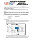
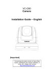
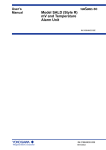
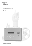
User’s Manual PH201G (Style B) Distributor IM 19B01E04-02E R IM 19B01E04-02E 6th Edition Blank Page i <INTRODUCTION> INTRODUCTION This instruction manual describes the procedures for installing, wiring and carrying out simple maintenance on the PH201G distributor used in the “2-wire Type Transmitter System”. Please read this instruction manual through completely before working with the PH201G. Media No. IM 19B01E04-02E 6th Edition : Apr. 2014 (YK) All Rights Reserved Copyright © 2000, Yokogawa Electric Corporation IM 19B01E04-02E ii <INTRODUCTION> For the safe use of this equipment n Safety, Protection, and Modification of the Product • In order to protect the system controlled by the product and the product itself and ensure safe operation, observe the safety precautions described in this user’s manual. We assume no liability for safety if users fail to observe these instructions when operating the product. • If this instrument is used in a manner not specified in this user’s manual, the protection provided by this instrument may be impaired. • Be sure to use the spare parts approved by Yokogawa Electric Corporation (hereafter simply referred to as YOKOGAWA) when replacing parts or consumables. • Modification of the product is strictly prohibited. • The following symbols are used in the product and user’s manual to indicate that there are precautions for safety: n Notes on Handling User’s Manuals • Please hand over the user’s manuals to your end users so that they can keep the user’s manuals on hand for convenient reference. • Please read the information thoroughly before using the product. • The purpose of these user’s manuals is not to warrant that the product is well suited to any particular purpose but rather to describe the functional details of the product. • No part of the user’s manuals may be transferred or reproduced without prior written consent from YOKOGAWA. • YOKOGAWA reserves the right to make improvements in the user’s manuals and product at any time, without notice or obligation. • If you have any questions, or you find mistakes or omissions in the user’s manuals, please contact our sales representative or your local distributor. n Warning and Disclaimer The product is provided on an “as is” basis. YOKOGAWA shall have neither liability nor responsibility to any person or entity with respect to any direct or indirect loss or damage arising from using the product or any defect of the product that YOKOGAWA can not predict in advance. IM 19B01E04-02E iii <INTRODUCTION> n Symbol Marks Throughout this user’s manual, you will find several different types of symbols are used to identify different sections of text. This section describes these icons. WARNING Indicates a potentially hazardous situation which, if not avoided, could result in death or serious injury. CAUTION Indicates a potentially hazardous situation which, if not avoided, may result in minor or moderate injury. It may also be used to alert against unsafe practices. IMPORTANT Indicates that operating the hardware or software in this manner may damage it or lead to system failure. NOTE Draws attention to information essential for understanding the operation and features. IM 19B01E04-02E iv <INTRODUCTION> After-sales Warranty n Do not modify the product. n During the warranty period, for repair under warranty consult the local sales representative or service office. Yokogawa will replace or repair any damaged parts. Before consulting for repair under warranty, provide us with the model name and serial number and a description of the problem. Any diagrams or data explaining the problem would also be appreciated. l If we replace the product with a new one, we won’t provide you with a repair report. l Yokogawa warrants the product for the period stated in the pre-purchase quotation Yokogawa shall conduct defined warranty service based on its standard. When the customer site is located outside of the service area, a fee for dispatching the maintenance engineer will be charged to the customer. n In the following cases, customer will be charged repair fee regardless of warranty period. • Failure of components which are out of scope of warranty stated in instruction manual. • Failure caused by usage of software, hardware or auxiliary equipment, which Yokogawa Electric did not supply. • Failure due to improper or insufficient maintenance by user. • Failure due to modification, misuse or outside-of-specifications operation which Yokogawa does not authorize. • Failure due to power supply (voltage, frequency) being outside specifications or abnormal. • Failure caused by any usage out of scope of recommended usage. • Any damage from fire, earthquake, storms and floods, lightning, disturbances, riots, warfare, radiation and other natural changes. n Yokogawa does not warrant conformance with the specific application at the user site. Yokogawa will not bear direct/indirect responsibility for damage due to a specific application. n Yokogawa Electric will not bear responsibility when the user configures the product into systems or resells the product. n Maintenance service and supplying repair parts will be covered for five years after the production ends. For repair for this product, please contact the nearest sales office described in this instruction manual. IM 19B01E04-02E v <CONTENTS> PH201G (Style B) Distributor IM 19B01E04-02E 6th Edition CONTENTS INTRODUCTION....................................................................................................i For the safe use of this equipment....................................................................ii After-sales Warranty...........................................................................................iv 1.Overview..................................................................................................... 1-1 1.1 Standard Specifications.................................................................................... 1-1 1.2 Model and Suffix Codes.................................................................................... 1-2 1.3 External Dimensions......................................................................................... 1-3 2.Installation.................................................................................................. 2-1 3. 4. 2.1 Unpacking, and Verifying Specifications........................................................ 2-1 2.2 PH201G Distributor Construction.................................................................... 2-2 2.3 Rack Construction............................................................................................. 2-3 2.4 Mounting............................................................................................................. 2-4 2.5 Removing the Internal Unit............................................................................... 2-6 2.6 External Wiring................................................................................................... 2-7 Operating Principles................................................................................. 3-1 3.1 Loop Isolation..................................................................................................... 3-1 3.2 Communications Function............................................................................... 3-2 Operation.................................................................................................... 4-1 4.1 Components....................................................................................................... 4-1 4.2 Pre-Operation Checks....................................................................................... 4-2 4.3 Communication Output..................................................................................... 4-2 5.Maintenance............................................................................................... 5-1 5.1 6. Fuse Replacement............................................................................................. 5-1 Trouble shooting....................................................................................... 6-1 6.1 Troubleshooting Flowchart.............................................................................. 6-2 6.2 Part Replacement Procedure........................................................................... 6-3 6.2.1 Power Unit Removal........................................................................... 6-3 6.2.2 Main Card Removal............................................................................ 6-3 6.2.3 Cover Removal................................................................................... 6-3 Customer Maintenance Parts List........................................... CMPL 19B1E4-01E Revision Information................................................................................................i IM 19B01E04-02E Blank Page < 1. Overview > 1-1 1.Overview This distributor, designed exclusively for use with these 2-wire transmitter, supplies drive power to the 2-wire transmitter while simultaneously receiving 4 to 20 mA DC current signal from the transmitter and converting it to 1 to 5 V DC voltage signal; it also simultaneously receives a digital signal superimposed on 4 to 20 mA DC signal, and provides contact outputs during hold, failure, and / or cleaning. A current limiter function is built into this unit so it can continue to operate properly even with a short circuit on the transmitter side. 1.1 Standard Specifications <Input / Output Signal Specifications> Number of input points (Number of transmitter units connectable): 1 point Output signal: 1 to 5 V DC (2 points) Load resistance: 2 kΩ or more (1 to 5 V DC Output) Isolation system: Loop isolation type <Mounting / Form> Mounting method: Indoor rack mounting Connection method: External signal connection: M4 screw terminal connection Power supply / Ground connection: 100 V: JIS C8303 ground type 2 plug connection 220 V: CEE 7VII (European electrical device standard) plug connection Cable length: 300 mm External dimensions: 180H x 48W x 300D mm Weight: Approx. 1.7 kg (Including rack and case) <Standard Specifications> Accuracy: ±0.2 % of span Transmitter supply voltage: 26.5 ± 1.5 V DC Insulation resistance Between I/O terminals and ground pin: 100 MΩ / 500 V DC Between power supply pins and ground pin: 100 MΩ / 500 V DC <Operating Specifications> Ambient temperature: 0 to 50 °C Ambient humidity: 5 to 90 % RH (Non-condensing) Power supply: Dual use AC/DC 100 V: DC power 20 to 130 V, no polarity AC power 80 to 138 V, 47 to 63 Hz 220 V: DC power 120 to 340 V, no polarity AC power 138 to 264 V, 47 to 63 Hz Maximum current and power consumption 24 V DC: Approx. 200 mA 100 V AC: Approx. 7 VA 220 V AC: Approx. 11 VA IM 19B01E04-02E 1-2 < 1. Overview > <Contact Output> Contact rating: 250 V AC, maximum 100 VA 220 V DC, maximum 50 VA Hold contact output: N.C. 1 contact, Normally energized Contact closes when power is off or during maintenance. Failure contact output: N.C. 1 contact, Normally energized Contact closes when power is off or during failure. Cleaning contact output:1 contact, Close during cleaning only Used as drive contact for solenoid valve for cleaning. <Regulatory Compliance> Korea Electromagnetic Conformity Standard Class A 한국 전자파적합성 기준 A급 기기 (업무용 방송통신기자재) 이 기기는 업무용(A급) 전자파적합기기로서 판매자 또는 사용자는 이 점을 주의하시기 바라며, 가정외의 지역에서 사용하는 것을 목적으로 합니다. 1.2 Model and Suffix Codes Model Suffix Code Option Code Specification PH201G ••••••••••••••••••••• •••••••••••••••••• Distributor Power Supply -A1 -A2 — Option IM 19B01E04-02E •••••••••••••••••• 100 V AC •••••••••••••••••• 220 V AC *B •••••••••••••••••• Style B /TB Terminal for Power connection 1.3 1-3 < 1. Overview > External Dimensions Unit : mm 48 136 180 160 79 2-ø5.8 Mounting Holes 303 Grounded Power code Figure 1.1 PH201G-Au*B Distributor External Dimensions Unit : mm 48 136 180 160 79 303 2-ø5.8 Mounting Holes Figure 1.2 PH201G-Au*B/TB Distributor External Dimensions IM 19B01E04-02E Blank Page < 2. Installation > 2-1 2.Installation 2.1 Unpacking, and Verifying Specifications This instrument was thoroughly inspected at the factory before shipment. When you have received it, please check visually to verify that no damage has occurred. Also check that the spare fuse, a standard accessory, is present. The model and suffix codes are inscribed on the nameplate attached to the front of the instrument. Check the product model and suffix codes on the instrument’s nameplate against those listed in Section 1.2 to verify that the product is exactly what was ordered. Should any questions arise, please contact your sales representative or YOKOGAWA sales office. The spare fuse is located inside. DISTRIBUTOR MODEL PH201G SUFFIX -A 1* B SUPPLY 80 - 138V AC 47 -63Hz 20 - 130V DC NO. Figure 2.1 Location of Nameplate IM 19B01E04-02E 2-2 < 2. Installation > 2.2 PH201G Distributor Construction The PH201G distributor is a rack instrument. It has a 2-piece construction that enables the internal unit to be separated from the rack case. The internal unit is connected to the rack case by a multi pin connector so that it can be inserted and removed without disconnecting the external wiring to the instrument’s terminals. However, in the case of a terminal-connected power-supply wired distributor, or if wiring is connected to the contact signal terminals on the internal unit, that wiring must be removed. The rack-case terminal-board cover can be used as a handle for pulling out the internal unit. Input/outpit terminal board Terminal cover and handle for pulling out internal unit Rack case These terminala are not used. Multipin connector Grounded power plug Contact signal terminals Note: The figure shows the Model PH201G-A*B distributor. The PH201G-A*B/TB lacks a power cord with a ground plug, having instead a power connection terminal board on the internal unit. Figure 2.2 IM 19B01E04-02E PH201G Distributor Construction Rack Construction The PH201G distributor can be mounted on the same rack as other YOKOGAWA rack instruments. Figure 2.3 is a configuration for mounting several rack instruments as a group. The angle iron used for mounting must be strong enough to support all of the instruments. The example in Figure 2.3 illustrates general practice, using an angle iron 40340 mm wide and 5 mm thick. For safety, and to prevent problems with the cables used for electrical wiring, use a plastic wiring duct, and run the wiring that connects to the instruments through this dust. Unless terminal board connection is specifically desired, the rack instrument power supply and ground connections are provided via a power cord and plug (a two-prong plug with a ground connection, JIS C8303, for 15 A, 125 V service). Connect this plug to a compatible receptacle (See Figure 2.4) Unit: mm 25 50 50 50 50 Mounting screw hole M5 x 0.8 Angle (40 x 40 x 5) 25 or more 140 160 220 2.3 2-3 < 2. Installation > 25 or more Rack support Figure 2.3 Wiring duct Rack Configuration (Example) • Receptacle strip separate from duct • Receptacle strip mounted directly on duct Wiring duct Wiring duct Multi-receptacle strip Multi-receptacle strip Figure 2.4 Examples of Mounting a Receptacle Strip IM 19B01E04-02E 2-4 < 2. Installation > 2.4 Mounting The PH201G distributor can be mounted with the internal unit in the rack case, but mounting is easier if the internal unit is removed. (1) Insert the case into the rack. Orient the case so that the multipin connector is on the left. Align the two mounting holes on the case with the screw holes on the rack, and fasten the case in place with two mounting screws (M5x0.8) [see Figure 2.5]. Figure 2.5 Rack-Case Mounting (2) Pass the electrical wires through the wiring duct and pull them out. Run the wires connecting to the input / output terminal board through the upper duct; through the lower duct run the wires connecting to the contact signal output terminals, and also the power wiring in the case of a terminal-connected power wired model (see Figure. 2.6) Do not connect the wiring to the contact signal output terminals, or to the power supply / ground terminals of a terminal-connected power model, at this time; wait until after the internal unit is plugged into the case in (4) below. Figure 2.6 Wiring (3) Connect the wiring that has been pulled through the ducts to the appropriate terminals. See Section 2.6, “External Wiring”, concerning connections to individual terminals. IM 19B01E04-02E 2-5 < 2. Installation > (4) Plug the internal unit into the case, being careful to make sure that you are inserting it in the proper location. There are labels on the internal unit and the case. If tag numbers have been assigned to the labels, compare them and make sure that they match before inserting the internal unit (see Figure 2.7). If using contact signal out puts, or terminal-connected power wiring, connect the relevant wires to the appropriate terminals. Label Front view Figure 2.7 Rack case Location of Labels (5) Replace the cover on the terminal section. If the instrument has a power cord, insert the power plug into the receptacle above the instrument (see Figure 2.8). Figure 2.8 Placement of Internal Unit IM 19B01E04-02E 2-6 < 2. Installation > 2.5 Removing the Internal Unit It is sometimes necessary to remove the internal unit from the case to make adjustments and carry out maintenance on the instrument. This section describes the procedure for removing the internal unit in such cases. To remove the internal unit, it is not necessary to remove the terminal board wiring. Because the internal unit and the terminal board (case) are connected by a multipin connector, separating them at this connector enables the internal unit to be removed from the case while leaving the wiring to the terminal board in place. However, if there is wiring to the contact signal terminals on the front of the internal unit, or if it is a terminal-connected power wired model, that wiring must be removed. (1) Unplug the power cord from the receptacle. (2) Pull the terminal cover down toward you. The cover also serves as a handle for removing the internal unit. Hook your fingers around the terminal cover and pull out the internal unit. Figure 2.9 Internal Unit Removal (1) Figure 2.10 Internal Unit Removal (2) IM 19B01E04-02E 2.6 2-7 < 2. Installation > External Wiring (1) Mount round M4-screw crimp terminal lugs on the wires to be connected to the terminals. (2) If the internal unit is already installed in the rack case, pull the terminal cover down away from the terminals and connect the wires. Wiring to the terminals on the internal unit such as wiring to the contact signal terminals should also be done with their terminal covers removed. (3) Refer to Figure 2.11 or 2.12 to identify the individual terminals to which to connect the wiring. (4) After completing wiring, be sure to reinstall the contact signal terminal cover and the internal unit serves also as a lock to prevent the internal unit from being removed from the case accidentally. Check that the internal unit is firmly inserted. Terminal symbol A B C D F H J K 1 2 3 4 5 6 7 8 K J B D H A C F a c e b d f 1 3 5 2 4 6 7 8 Figure 2.11 Terminal for contact signals Signal name + OUT1(1 to 5V DC) CMN(Common) OUT2 (1 to 5V DC) CMN(Common) CMN (For safety barrier) (Not used) (Not used) Contact signals a,b c,d e,f HOLD (hold) FAIL (failure) WASH (cleaning) (Note) Terminal symbol mark of "a" to "f" for contact signals are not printed. Terminal Assignment Diagram and Wiring (For Units with a Power Cord) IM 19B01E04-02E 2-8 < 2. Installation > K J B D H A C F L N a c e b d f 1 3 5 2 4 6 7 8 Power supply Contact signal terminals Terminal symbol A B C D F H J K 1 2 3 4 5 6 7 8 Signal name + OUT1(1 to 5V DC) CMN(Common) OUT2 (1 to 5V DC) CMN(Common) CMN (For safety barrier) (Not used) (Not used) Contact signals a,b c,d e,f L,N HOLD (hold) FAIL (failure) WASH (cleaning) Power supply (AC or DC, either polarity) Grounding (Note) Terminal symbol mark of "a" to "f" for contact signals are not printed. Figure 2.12 Terminal Assignment Diagram and Wiring (For Units with Terminal-Connected Power Supply Wiring) IM 19B01E04-02E 3-1 < 3. Operating Principles > 3. Operating Principles 3.1 Loop Isolation For a two-wire transmitter, approximately 26.5 V is supplied through a current regulator CL, and a 4 to 20 mA current signal is obtained. The current regulator orevents excessive current when there is a short circuit in the field wiring. The current signal is converted to 1 to 5 V, which passes through an output amplifier to become the output signal. Communication output 2-wire Transmitter + Wave shaping circuit Signal separator Bandpass filter Fail Noise detection circuit CL + - OUT 2 + - Filter Wash Hold + - - Relay drive circuit Relay contact outputs + OUT 1 - CMN CL: Current regulator SWR: Switching regulator power supply SWR L1 Figure 3.1 L2 GND PH201G Distributor Block Diagram IM 19B01E04-02E 3-2 < 3. Operating Principles > 3.2 Communications Function If the communications setting of a 2-wire transmitter is set to “communications ON”, as AC signal of approximately 500 Hz (approximately 2 mA p-p) is superimposed on the 4 to 20 mA line. Within this signal, “fail”, “wash”, and “hold” signals are incorporated as serial signals. The PH201G distributor distinguished ON and OFF individually for each of these three types of signals, and outputs them as relay contact signals. The signal update interval is approximately 1.2 seconds. Notice: Jumper J1 in the upper middle of the printed circuit board is the Jumper associated with the communication operation. Normally position of the jumper J1 is set to the <a>. When the communication operation is not stable, you can set to <b>. IM 19B01E04-02E 4. 4-1 < 4. Operation > Operation After mounting and wiring have been completed, you need only turn on the power to set this instrument in operation. Before beginning operation, you should first perform the inspections and check in Section 4.2. Note that no operator actions or manipulations are required when this instrument is operating. 4.1 Components Note: The figure shows the Model PH201G-A*B distributor. The PH201G-A*B/TB lacks a power cord with a ground plug, having instead a power connection terminal board on the internal unit. Input/output terminal board Internal unit Terminal cover and handle for pulling out internal unit Rack case Multipin connector Grounded power plug Figure 4.1 Contact signal terminals Components IM 19B01E04-02E 4-2 < 4. Operation > 4.2 Pre-Operation Checks Before beginning operation, inspect / check the following Items. (1) Pull out the internal unit and check that the fuse installation in the fuse holder at the rear of the internal unit is of the proper rating for the power source. When returning the internal unit to the rack case, make sure that the connector that connects the internal unit and the case is properly mated. (2) Check that external wiring to the terminal boards has been performed correctly. (3) If the unit has a power cord, check that the grounded power plug is correctly inserted into the receptacle. 4.3 Communication Output The individual relay contact outputs for “fail”, “wash”, and “hold” will be in the states shown below depending on whether the power is ON or OFF for a PH201G distributor, and whether communications are ON or OFF for a 2-wire transmitter. Table 4.1 Transmitter Communication communications and power status PH201G power Fail Contact IM 19B01E04-02E OFF — OFF Immediately after ON Closed Open ON ON Open Communications output Wash Open Open Open Communications output Hold Closed Open Open Communications output < 5. Maintenance > 5-1 5.Maintenance 5.1 Fuse Replacement When a fuse open-circuits, investigate and deal with the cause, and then replace the fuse as below. If the cause of the loss of continuity is the fuse itself, it is possible that the fuse holder is dirty or the contact is bad, and this should be checked. (1) Detach the open fuse by pulling it strongly in the direction indicated by the arrow in Figure 5.1, and remove it. (2) Install a new fuse, after checking its rating. Fuse Rated current: 1 A P/N: A1609EF Figure 5.1 Fuse Replacement IM 19B01E04-02E Blank Page 6. < 6. Trouble shooting > 6-1 Trouble shooting If a problem occurs during operation, take corrective action according to the troubleshooting flowchart in Section 6.1. Consult your YOKOGAWA service representative if serious trouble is suspected. IM 19B01E04-02E 6-2 < 6. Trouble shooting > 6.1 Troubleshooting Flowchart Problem Communication error? YES YES Is the 2-wire cable shielded? NO NO Is signal update taking place? Change to a shielded wire Is output 0 % or below? NO Is output 100 % or above? YES Is the fuse open? YES NO Are communications ON at the 2-wire transmitter? YES Replace fuse and recheck YES NO Check the noise on the 2-wire line NO Turn communications ON YES NO Recheck the error condition Normal? Replace the main card and recheck NO Normal? YES NO Replace the power unit and recheck Normal? NO Recheck the error condition IM 19B01E04-02E YES Does update take too much time? (See Section 5.3) NO Input / output accuracy problem NO YES YES End YES End 6.2 6-3 < 6. Trouble shooting > Part Replacement Procedure The following shows the disassembly procedures to be used when replacing parts. Disassembly should be limited to a minimum; disassemble carefully, and no more than necessary. To reassemble after replacing a part, perform the disassembly procedures in reverse order. 4 Power unit 1 2 6 3 Main card 8 5 6 7 6 6 Figure 6.1 PH201G Distributor Construction Drawing 6.2.1 Power Unit Removal (1) Remove connector 3 from 1. (2) Remove screw 4 (in two places). (3) Power unit 1 can be removed by pulling it out from main card 5. The card 5 and power unit 1 are connected by a connector. 6.2.2 Main Card Removal (1) Remove screw 6 (in six places). (2) Remove 5 from 1 and 7. 6.2.3 Cover Removal (1) Cover 8 can be removed easily by spreading the rotating section. IM 19B01E04-02E Blank Page Customer Maintenance Parts List Model PH201G (*B) DISTRIBUTOR 3 1 3 2 3 3 4 7 3 6 5 3 3 3 Item Parts No. 1 2 3 4 5 6 7 E9715YB E9715YS A1609EF Y9306JB K9312EF E9713CK E9713EG E9713FS S9079PB Qty 1 1 1 8 1 1 1 1 1 Description Power Supply Unit (for 100V Version) Power Supply Unit (for 220V Version) Fuse 1A Pan H. Screw, M3 x 6 Main Board Assembly Cover Cable Assembly (for 100V Version) Cable Assembly (for 220V Version) Bushing All Rights Reserved, Copyright © 1989, Yokogawa Electric Corporation. Subject to change without notice. CMPL 19B1E4-01E 3rd Edition : Mar. 2012 i Revision Information : PH201G (Style B) Distributor Title Manual No. : IM 19B01E04-02E Apr. 2014/6th Edition Section 1.1; Addition of Regulatory Compliance. Jun. 2012/5th Edition Page layout changed by InDesign Feb. 2010/4th Edition Some of illustrations has been replaced more clearly drawings (no contents changed). Jul. 2007/3rd Edition All over revised: Addition of “For the safe use of this equipment” and “After Sales Warranty”; Sec. 1 Overview revised corresponding to GS.; CMPL 19B1E4-01E revised to 2nd ed. (some parts added) Mar. 2002/2nd Edition Some error correction. Nov. 2000/1st Edition Newly published. n If you want to have more information about Yokogawa products, you can visit Yokogawa’s home page at the following web site. Home page: http://www.yokogawa.com/an IM 19B01E04-02E Blank Page