1
HC900 Hybrid Controller
Installation and User Guide
Doc. No.:
Honeywell Process Solutions
51-52-25-107
Revision:
16
Date:
October 2009
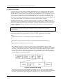
About This Document
Warranty/Remedy
Notices and Trademarks
Copyright 2009 by Honeywell
Revision 16 October 2009
Warranty/Remedy
Honeywell warrants goods of its manufacture as being free of defective materials and faulty workmanship. Contact
your local sales office for warranty information. If warranted goods are returned to Honeywell during the period of
coverage, Honeywell will repair or replace without charge those items it finds defective. The foregoing is Buyer's sole
remedy and is in lieu of all other warranties, expressed or implied, including those of merchantability and
fitness for a particular purpose. Specifications may change without notice. The information we supply is believed
to be accurate and reliable as of this printing. However, we assume no responsibility for its use.
While we provide application assistance personally, through our literature and the Honeywell web site, it is up to the
customer to determine the suitability of the product in the application.
Honeywell Process Solutions
512 Virginia Drive
Fort Washington, PA 19034
Honeywell is a U.S. registered trademark of Honeywell
Other brand or product names are trademarks of their respective owners.
Revision 16
10/09
HC900 Hybrid Controller Installation and User Guide
ii
About This Document
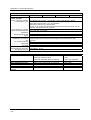
Abstract
This document provides descriptions and procedures for the installation, operation and maintenance of the HC900
Hybrid Controller hardware.
References
The following list identifies all documents that may be sources of reference for material discussed in this
publication.
Document Title
ID #
HC900 Hybrid Controller Technical Overview Specification
51-52-03-31
HC900 Module Specification
51-52-03-41
HC900 Controlware Specification
51-52-03-42
Hybrid Control Designer Specification
51-52-03-43
HC900 Hybrid Controller Operator Interface User Guide
51-52-25-108
HC900 Hybrid Control Designer User Guide
51-52-25-110
HC900 Hybrid Control Utilities User Guide
51-52-25-126
HC900 Hybrid Controller Function Block Reference Guide
51-52-25-109
HC900 Hybrid Controller Communications User Guide
51-52-25-111
HC900 Controller Redundancy Overview & System Operation
51-52-25-133
900 Control Station For use with HC900 Hybrid Controller
51-52-25-148
Station Designer Software manual
51-52-25-149
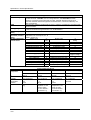
Contacts
World Wide Web
The following lists Honeywell’s World Wide Web sites that will be of interest to our customers.
Honeywell Organization
WWW Address (URL)
Corporate
http://www.honeywell.com
Honeywell Process Solutions
http://hpsweb.honeywell.com
Technical tips
http://hpsweb.honeywell.com/Cultures/enUS/Products/Instrumentation/hybrid/hc900/TechnicalTips/documents.htm
Telephone
Contact us by telephone at the numbers listed below.
Organization
United States and Canada
Revision 16
10/09
Honeywell
Phone Number
1-800-423-9883
1-800-822-7673
HC900 Hybrid Controller Installation and User Guide
Tech. Support
Service
iii
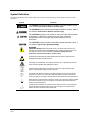
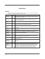
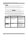
Symbol Definitions
The following table lists those symbols that may be used in this document and on the product to denote certain
conditions.
Symbol
Definition
This DANGER symbol indicates an imminently hazardous situation, which,
if not avoided, will result in death or serious injury.
This WARNING symbol indicates a potentially hazardous situation, which, if
not avoided, could result in death or serious injury.
This CAUTION symbol may be present on Control Product instrumentation
and literature. If present on a product, the user must consult the
appropriate part of the accompanying product literature for more
information.
This CAUTION symbol indicates a potentially hazardous situation, which, if
not avoided, may result in property damage.
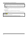
WARNING
PERSONAL INJURY: Risk of electrical shock. This symbol warns the user of a
potential shock hazard where HAZARDOUS LIVE voltages greater than 30 Vrms,
42.4 Vpeak, or 60 Vdc may be accessible. Failure to comply with these
instructions could result in death or serious injury.
ATTENTION, Electrostatic Discharge (ESD) hazards. Observe precautions for
handling electrostatic sensitive devices
CAUTION, HOT SURFACE: This symbol warns the user of potential hot surfaces
which should be handled with appropriate caution.
Protective Earth (PE) terminal. Provided for connection of the protective earth
(green or green/yellow) supply system conductor.
Functional earth terminal. Used for non-safety purposes such as noise immunity
improvement. NOTE: This connection shall be bonded to protective earth at the
source of supply in accordance with national and local electrical code requirements.
Earth Ground. Functional earth connection. NOTE: This connection shall be bonded
to Protective earth at the source of supply in accordance with national and local
electrical code requirements.
Chassis Ground. Identifies a connection to the chassis or frame of the equipment
shall be bonded to Protective Earth at the source of supply in accordance with
national and local electrical code requirements.
Revision 16
10/09
HC900 Hybrid Controller Installation and User Guide
iv
Contents
Symbo Definitions ........................................................................................................................................ iv
Introduction ..................................................................................................................... 1
Purpose ......................................................................................................................................................... 1
Model Selection Guide .................................................................................................................................. 2
Functional Description................................................................................................................................... 6
Feature Summary ......................................................................................................................................... 9
Components and Architecture....................................................................................... 10
Overview ..................................................................................................................................................... 10
Components ................................................................................................................................................ 10
Redundant components .............................................................................................................................. 13
Hardware Components ............................................................................................................................... 15
Ethernet Devices/Considerations................................................................................................................ 24
I/O Network ................................................................................................................................................. 25
Ethernet Open Connectivity Network.......................................................................................................... 26
Serial Ports (RS-232 and RS-485).............................................................................................................. 34
Pre-Installation Planning ............................................................................................... 39
Overview ..................................................................................................................................................... 39
AC Power Supply Selection for racks with I/O ............................................................................................ 40
DC Power Supply........................................................................................................................................ 41
Rack Orientation and Mounting .................................................................................................................. 41
Remote Termination Panels........................................................................................................................ 43
Environment ................................................................................................................................................ 43
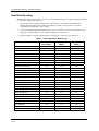
Heat Rise De-rating..................................................................................................................................... 44
Cable/Wiring Distance Planning ................................................................................................................. 45
Electrical Considerations............................................................................................................................. 47
System Monitor Function Blocks................................................................................................................. 54
Rack Installation ............................................................................................................ 55
Overview ..................................................................................................................................................... 55
Mount Racks ............................................................................................................................................... 58
Assemble Controller Rack........................................................................................................................... 60
Assemble I/O Expansion Racks.................................................................................................................. 65
Revision 16
10/09
HC900 Hybrid Controller Installation and User Guide
v
I/O Module Installation and Wiring ................................................................................ 67
Overview ..................................................................................................................................................... 67
Module Placement in Racks........................................................................................................................ 67
Remote Termination Panel (RTP)............................................................................................................... 70
Terminal Block-to-Field (Signal) Wiring ...................................................................................................... 70
Removal and Insertion Under Power (RIUP) .............................................................................................. 73
I/O Module Installation Procedures............................................................................................................. 74
I/O Terminal Block Wiring Diagrams........................................................................................................... 81
Communications Installation ....................................................................................... 113
Overview ................................................................................................................................................... 113
Wiring and cabling..................................................................................................................................... 113
Connecting the Operator Interface to the Controller................................................................................. 117
Connecting the HC900 Controller to a PC with the Hybrid Control Designer Software ........................... 118
Connecting the HC900 Controller to Modbus device(s) ........................................................................... 137
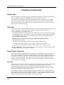
Operating Characteristics............................................................................................ 140
Introduction ............................................................................................................................................... 140
Overview ................................................................................................................................................... 140
Power Down / Power Up ........................................................................................................................... 140
Controller Modes....................................................................................................................................... 144
File Download/Upload Functions .............................................................................................................. 149
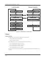
Redundant Operating Characteristics ......................................................................... 151
Overview ................................................................................................................................................... 151
Start-Up ..................................................................................................................................................... 151
Modes of operation (Figure 82)................................................................................................................. 151
Steady State Operations ........................................................................................................................... 152
Failover...................................................................................................................................................... 154
File Download/Upload Functions .............................................................................................................. 155
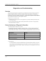
Diagnostics and Troubleshooting ................................................................................ 157
Overview ................................................................................................................................................... 157
External Indications of Diagnostic Information.......................................................................................... 157
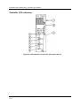
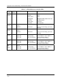
Controller CPU indicators.......................................................................................................................... 158
Scanner indicators .................................................................................................................................... 166
I/O Module Indicators ................................................................................................................................ 171
Ethernet Switch indicators......................................................................................................................... 174
Revision 16
10/09
HC900 Hybrid Controller Installation and User Guide
vi
Analog Calibration ....................................................................................................... 175
Overview ................................................................................................................................................... 175
Removal and Replacement Procedures...................................................................... 179
Overview ................................................................................................................................................... 179
Safety Considerations - PLAN AHEAD!.................................................................................................... 179
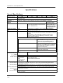
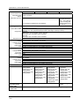
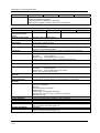
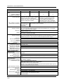
Specifications .............................................................................................................. 190
General Specifications .............................................................................................................................. 190
HC900 Analog Input Ranges vs. UMC800 Analog Input ranges .............................................................. 196
System Sizing and Availability Summary.................................................................................................. 199
Fiber Optics Recommendations................................................................................................................ 200
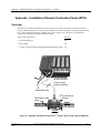
Appendix - Installation of Remote Termination Panels (RTPs)........................................... 203
Overview ................................................................................................................................................... 203
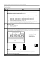
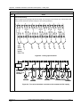
Analog Input .............................................................................................................................................. 204
Relay Output ............................................................................................................................................. 211
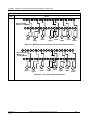
Analog Input/Digital Input/Digital Output/Analog Output........................................................................... 215
Latch/Unlatch RTP to rail .......................................................................................................................... 241
Declaration of Conformity ….………………………………………….…………………… 242
ATEX Certification ………………………………………….………………………………. 243
Index ……………………………………………………….………………………………… 245
Revision 16
10/09
HC900 Hybrid Controller Installation and User Guide
vii
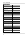
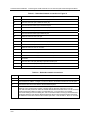
Tables
Table 1 – Descriptions of Major Components (Figure 4)........................................................................................ 12
Table 2 – Descriptions of Major Redundancy Components (Figure 5) ................................................................... 14
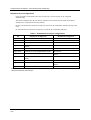
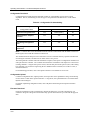
Table 3 – Serial port DIP switch settings ................................................................................................................ 35
Table 4 – Simultaneous serial port configurations .................................................................................................. 36
Table 5 – Power Applied, by Module Type............................................................................................................. 44
Table 6 – Guidelines for Grouping Wires ............................................................................................................... 51
Table 7 – Installation Tools ..................................................................................................................................... 55
Table 8 – Site and Equipment Preparation .............................................................................................................. 56
Table 9 – Mount Racks............................................................................................................................................ 58
Table 10 – Assemble C30/C50/C70 Controller Rack.............................................................................................. 60
Table 11 – Assemble C70R Controller Rack........................................................................................................... 63
Table 12 – Assemble I/O Expansion Racks............................................................................................................. 65
Table 13 – Minimum Recommended Wire Sizes .................................................................................................... 70
Table 14 – RIUP: Potential Hazards and Recommended Actions ........................................................................... 73
Table 15 – Connect Input/Output Wiring ................................................................................................................ 74
Table 16 – Typical Thermocouple resistance in Ohms per Double Foot @ 68 degrees F....................................... 81
Table 17 – Connect Communications Wiring and Cabling ................................................................................... 113
Table 18 – Links to Controller Communication Ports........................................................................................... 114
Table 19 – Parts needed to make RS-485 Cable.................................................................................................... 117
Table 20 – Null Modem Cable Connections.......................................................................................................... 120
Table 21 – Redundant Network connections in Figure 73..................................................................................... 131
Table 22 – Redundant network connections.......................................................................................................... 131
Table 23 – Controller Operating Modes ................................................................................................................ 146
Table 24 – Mode Switch Functions ....................................................................................................................... 147
Table 25 – Controller Behavior in Mode Transition ............................................................................................. 148
Table 26 – Configuration file downloading........................................................................................................... 150
Table 27 – LED Indications on Controller CPUs .................................................................................................. 159
Table 28 – Controller Status LED Diagnostics...................................................................................................... 160
Table 29 – LED Indications on Scanner Module................................................................................................... 166
Table 30 – Scanner LED Diagnostics.................................................................................................................... 167
Table 31 – LED Indications on I/O Module .......................................................................................................... 171
Table 32 – I/O Module LED Diagnostics .............................................................................................................. 172
Table 33 – Bad I/O Channel Diagnostics .............................................................................................................. 173
Table 34 – LED Indications on Ethernet Switch ................................................................................................... 174
Table 35 – Power Supply Replacement (all except C70R).................................................................................... 181
Table 36 – Controller Module Replacement.......................................................................................................... 183
Table 37 – Scanner Module Replacement ............................................................................................................. 184
Table 38 – RIUP: Potential Hazards and Recommended Actions ......................................................................... 185
Table 39 – I/O Module Replacement..................................................................................................................... 186
Table 40 – Installing Backup Battery (CPU not initialized) .................................................................................. 188
Table 41 – Replacing a Backup Battery (CPU Powered))..................................................................................... 189
Table 42 - HC900 PV Input Types and Ranges..................................................................................................... 196
Table 43 – System Size and Availability Summary .............................................................................................. 199
Table 44 – Fiber Optics Equipment Recommendations ........................................................................................ 200
Revision 16
10/09
HC900 Hybrid Controller Installation and User Guide
viii
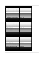
Figures
Figure 1 – Small HC900 Controller Configuration ................................................................................................... 6
Figure 2 – Expanded HC900 Controller Configuration (C50/C70 CPU only) .......................................................... 7
Figure 3 – Single process with redundancies............................................................................................................. 8
Figure 4 – Configuration with Multiple Controllers................................................................................................ 11
Figure 5 – Redundant Configuration with multiple I/O racks ................................................................................. 13
Figure 6 – Controller Rack Components ................................................................................................................. 15
Figure 7 – Redundant Controller Rack Components ............................................................................................... 15
Figure 8 – I/O Expansion Rack Components .......................................................................................................... 16
Figure 9 – Rack Options .......................................................................................................................................... 17
Figure 10 – Power Supply ....................................................................................................................................... 18
Figure 11 – Power Status Module (PSM)................................................................................................................ 19
Figure 12 – Controller Module ................................................................................................................................ 20
Figure 13 – Redundancy Switch Module ................................................................................................................ 21
Figure 14 – Scanner 1 Module................................................................................................................................. 21
Figure 15 – Scanner 2 Module................................................................................................................................. 22
Figure 16 – I/O Module Terminal Blocks ............................................................................................................... 22
Figure 17 – RS-232 Modem Devices ...................................................................................................................... 23
Figure 18 – HC900 Controller Configurations ........................................................................................................ 25
Figure 19 – Modular Network Structure.................................................................................................................. 29
Figure 20 – Modbus/TCP Framing.......................................................................................................................... 29
Figure 21 – Typical installation using a Cable Modem ........................................................................................... 33
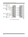
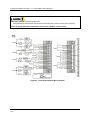
Figure 22 – Controller Serial Ports .......................................................................................................................... 34
Figure 23 – Serial Ports DIP Switch default settings............................................................................................... 35
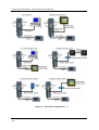
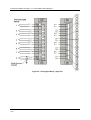
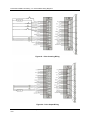
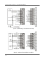
Figure 24 – Serial Port Configurations 1 – 6 ........................................................................................................... 37
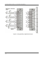
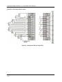
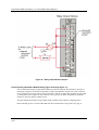
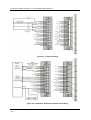
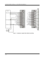
Figure 25 – Serial Port Configurations 7 – 11 ......................................................................................................... 38
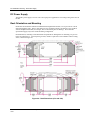
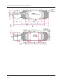
Figure 26 – Rack Dimensions (C30 and C50) ......................................................................................................... 41
Figure 27 – Rack Dimensions with reserve power supply....................................................................................... 42
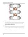
Figure 28 – Vertical Spacing of Racks (all models) ................................................................................................ 43
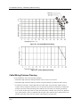
Figure 29 – AC Input Module de-Rating................................................................................................................. 45
Figure 30 – Power Supply de-Rating....................................................................................................................... 45
Figure 31 – Cabinet Wiring, Single Chassis............................................................................................................ 48
Figure 32 – Cabinet Wiring, Multiple Chassis ........................................................................................................ 49
Figure 33 – Redundant power supplies each with external fuse and switch............................................................ 50
Figure 34 – Master Control Relay Wiring Example ................................................................................................ 53
Figure 35 – I/O Module Installation ........................................................................................................................ 67
Figure 36 – Terminal Block Styles .......................................................................................................................... 69
Figure 37 – Signal-Wire Grounding ........................................................................................................................ 71
Figure 38 – Wire-Shield Grounding ........................................................................................................................ 71
Figure 39 – Terminal Block Jumper Installation ..................................................................................................... 72
Figure 40 – RTD Inputs........................................................................................................................................... 81
Figure 41 – Universal Analog Input Wiring Diagram ............................................................................................. 82
Figure 42 – Examples of RTD Input Wiring ........................................................................................................... 83
Figure 43 – Analog Input Wiring - Eight TCs......................................................................................................... 84
Figure 44 – Analog Input Wiring - Eight Resistance Inputs.................................................................................... 85
Figure 45 – Analog Input Wiring - Eight RTDs ...................................................................................................... 86
Figure 46 – Analog Input Wiring – Slidewire (Position Proportion Block) ............................................................ 87
Figure 47 – 16 point High Level Analog Input Wiring ........................................................................................... 88
Figure 48 – 4 channel Analog Output Wiring Diagram........................................................................................... 89
Figure 49 – 8 channel Analog Output Wiring Diagram........................................................................................... 90
Figure 50 – 16 channel Analog Output Wiring Diagram......................................................................................... 90
Figure 51 – DC Input Module Wiring Diagram ...................................................................................................... 92
Figure 52 – DC Input Module Jumper..................................................................................................................... 93
Figure 53 – 32 point DC Input Module Wiring ....................................................................................................... 94
Revision 16
10/09
HC900 Hybrid Controller Installation and User Guide
ix
Figure 54 – AC Input Module Wiring Diagram ...................................................................................................... 95
Figure 55 – AC Input Module Jumper..................................................................................................................... 96
Figure 56 – Contact Input Wiring Diagram............................................................................................................. 98
Figure 57 – DC Output Module Wiring Diagram.................................................................................................. 100
Figure 58 – DC Output Jumpers............................................................................................................................ 101
Figure 59 – 32 point DC Output Module Wiring .................................................................................................. 102
Figure 60 – AC Output Module Wiring Diagram.................................................................................................. 104
Figure 61 – AC Output Module Jumper ................................................................................................................ 105
Figure 62 – Schematic Example: Relay Output and External Wiring ................................................................... 106
Figure 63 – Relay Output Module Wiring Diagram .............................................................................................. 107
Figure 64 – Relay Output Module Jumpers........................................................................................................... 108
Figure 65 – Pulse Counting Wiring ....................................................................................................................... 109
Figure 66 – Pulse Output Wiring........................................................................................................................... 109
Figure 67 – Frequency Wiring............................................................................................................................... 110
Figure 68 – Quadrature, Differential, External Power Wiring............................................................................... 110
Figure 69 – Quadrature, Single Ended, External Power Wiring............................................................................ 111
Figure 70 – Quadrature, Differential, HC900 Power Wiring ................................................................................ 111
Figure 71 – Quadrature, Single Ended, HC900 Power Wiring.............................................................................. 112
Figure 72 – RS-232 Remote Access via Modems ................................................................................................. 121
Figure 73 – Redundant Networks (see Table 21) .................................................................................................. 130
Figure 74 – Two redundant systems with PC supervision..................................................................................... 133
Figure 75 - RS-485 Modbus slave wiring.............................................................................................................. 137
Figure 76 - RS-485 Modbus slave wiring with isolation ....................................................................................... 138
Figure 77 - XYR 5000 RS-485 Modbus connections with isolator ....................................................................... 139
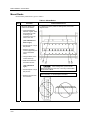
Figure 78 – Warm Start Operation ........................................................................................................................ 142
Figure 79 – Cold Start Operation........................................................................................................................... 143
Figure 80 – Mode Switches: Controller (left), RSM (right) .................................................................................. 147
Figure 81 – Pathways for Upload/Download Transactions ................................................................................... 149
Figure 82 – Modes of operation on RSM .............................................................................................................. 152
Figure 83 – Lead/Controller synchronization ........................................................................................................ 154
Figure 84 – LED Indicators on Controller CPUs (See Table 27) .......................................................................... 158
Figure 85 – LED Indicators on Scanners—1 port (left), 2 port (right) (See Table 29).......................................... 166
Figure 86 – I/O Module LED indicators................................................................................................................ 171
Figure 87 – Terminal Board Connections for AI Calibration ................................................................................ 177
Figure 88 – Terminal board Connections for AO Calibration ............................................................................... 178
Figure 89 – Extended Distance Example #1.......................................................................................................... 200
Figure 90 – Extended Distance Example #2.......................................................................................................... 201
Figure 91 – Example installation (not shown: 2nd RTP & cable for high capacity AI/DI/DO) ............................. 204
Figure 92 – Analog input terminals ....................................................................................................................... 206
Figure 93 – Two–wire transmitter connections with common 24 VDC supply .................................................... 206
Figure 94 – Milliamp input connections with 250 ohm shunt resistance............................................................... 207
Figure 95 – Volt, millivolt input connections........................................................................................................ 207
Figure 96 – Three-wire RTD input connections .................................................................................................... 208
Figure 97 – Two-wire RTD or ohm input connections.......................................................................................... 208
Figure 98 – Slidewire feedback connections for actuators .................................................................................... 209
Figure 99 Voltage input connections ................................................................................................................... 233
Figure 100 Current connections with 2-wire transmitter ....................................................................................... 233
Revision 16
10/09
HC900 Hybrid Controller Installation and User Guide
x
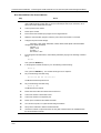
Introduction
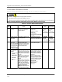
Purpose
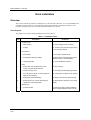
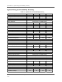
This publication describes the installation, operation, and maintenance of the Honeywell HC900 Hybrid
Controller. This publication includes the following sections.
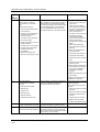
Chapter Title
Page
Content
Introduction
1
Model numbers, how to verify component compatibility, function description of
components, feature summary.
Components and
Architecture
10
Functional features and physical characteristics of the system and of each major
component of the HC900 Hybrid Controller. Networking components and
methods of interconnection.
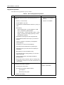
Pre-Installation
Planning
39
Pre-planning considerations and procedural guidelines for planning an installation.
Rack Installation
55
Procedures for installing the major components of the system: controller rack, I/O
expansion racks, and communication interconnections.
I/O Module
Installation and
Wiring
67
Procedures for installing I/O modules in the controller rack and I/O expansion
racks, and for wiring field devices to the terminal block associated with each
I/O module.
Communications
Installation
113
Guidelines for installing RS-232, RS-485, and Ethernet cabling and associated
components.
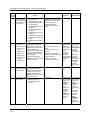
Operating
Characteristics
140
Characteristics of the HC900 Hybrid Controller as they relate to configuration of a
control strategy, and to operation of an installed and running system.
Redundant
Operating
Characteristics
151
Characteristics of redundant operation.
Diagnostics and
Troubleshooting
157
Mechanisms that detect and react to faults in the operation of HC900 Hybrid
Controller hardware and/or software components.
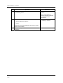
Analog Calibration
175
Hardware configuration required for calibrating AI and AO modules from the
configuration software.
Removal and
Replacement
Procedures
179
Guidelines for replacing system components; includes Cautions and Warnings as
applicable.
Specifications
190
Details of HC900 Hybrid Controller design and functioning.
Appendix Installation of Remote
Termination Panels
(RTPs)
203
The Remote Termination Panel (RTP) provides an easy way to connect the
HC900 controller to the field wiring. The RTP integrates some of the typical
externally connected components, reducing wiring and setup time. It also
minimizes the need for multiple wires under a single screw connection by
expanding the connectivity of the shared terminals of the I/O modules.
Revision 16
10/09
HC900 Hybrid Controller Installation and User Guide
1
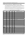
Introduction - Model Selection Guide
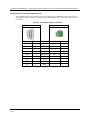
Model Selection Guide
Description
Model number
Racks
4 I/O Slot Rack
900R04 – 0001
8 I/O Slot Rack
900R08 – 0101
12 I/O Slot Rack
900R12 - 0101
8 Slot Rack -Red. Power
900R08R - 0101
12 Slot Rack - Red. Power
900R12R - 0101
Redundant CPU Rack
900RR0 - 0001
Controllers
Controller C50 CPU Config.SW & Docs
900C51 – 00XX-00
Controller C50 CPU
900C52 – 00XX-00
Controller C30 CPU Config. SW & Docs
900C31 – 00XX-00
Controller C30 CPU
900C32 – 00XX-00
Controller C70 CPU Config.SW & Docs
900C71-00XX-00
Controller C70 CPU
900C72-00XX-00
Controller C70R CPU Config.SW & Docs
900C71R-0000-XX
Controller C70R CPU
900C72R-0000-XX
Redundancy switch module
900RSM - 0001
I/O Scanner - 2 Port (1 per I/O rack)
900C73R-0000-XX
I/O Scanner (for remote rack)
900C53 – 00XX-00
Redundant Power Status Module
900PSM - 0001
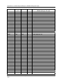
Power Supplies
120/240VAC, 60W
900P01 -0001
120/240VAC, 28W
900P02 -0001
+24VDC
900P24-0001
I/O Modules
Analog Input (8 channel)
900A01 - 0102
High Level Analog Input (16 channel)
900A16 - 0001
Analog Output, 0 to 20mA, (4 channel)
900B01 -0101
Analog Output, 0 to 20mA, (8 channel)
900B08 – 0001
Analog Output, 0 to 20mA, (16 channel)
900B16 - 0001
Digital Input, Contact type, (16 channel)
900G01 - 0102
Digital Input, 24VDC (16 channel)
900G02 - 0102
Digital Input, 24VDC (32 channel)
900G32 - 0001
Digital Input, 120/240 VAC, (16 channel)
900G03 - 0102
Digital Output, Relays ( 8 channel)
900H01 - 0102
Digital Output, 24VDC (16 channel)
900H02 - 0102
Digital Output, 24VDC (32 channel)
900H32 - 0001
Digital Output, 120/240 VAC (8 channel)
900H03 - 0102
Pulse/Frequency/Quadrature
900K01 - 0001
Revision 16
10/09
HC900 Hybrid Controller Installation and User Guide
2
Introduction - Model Selection Guide
Description
Model number
I/O Components
Low VoltageTerminal Block (Euro style)
900TEK - 0001
Low VoltageTerminal Block (Barrier Style)
900TBK -0001
High VoltageTerminal Block (Euro style)
900TER - 0001
High Voltage Terminal Block (Barrier Style)
900TBR - 0001
High Density Terminal Block
900TCK - 0001
Analog Input Remote Terminal Panel (RTP)
900RTA - L001
I/O Components
Relay Output Remote Terminal Panel (RTP)
900RTR - H001
DI, DO, AO Remote Terminal Panel (RTP)
900RTS - 0001
Low Voltage RTP Cable (1.0M, 3.28ft.)
900RTC - L010
Low Voltage RTP Cable (2.5M, 8.2ft.)
900RTC - L025
Low Voltage RTP Cable (5.0M, 16.4ft.)
900RTC - L050
High Voltage RTP Cable (1.0M, 3.28ft.)
900RTC - H010
High Voltage RTP Cable (2.5M, 8.2ft.)
900RTC - H025
High Voltage RTP Cable (5.0M, 16.4ft.)
900RTC - H050
High Density RTP Cable (1.0M, 3.28ft.)
900RTC - 3210
High Density RTP Cable (2.5M, 8.2ft.)
900RTC - 3225
Filler Block Terminal Cover
900TNF - 0001
Shield Terminal Strip (package of 2)
900TSS - 0001
Terminal board jumpers (10, two pos jumpers)
900J02 - 0001
Terminal board jumpers (10, ten pos.jumpers)
900J10 - 0001
Manuals
Full Document set on CD
900ME1-00XX-XX
Full document set, hard copy - Engish
900ME2-00XX-XX
Software
HC Designer Config. Software CD
900W01-00XX-XX
HC Utilities Software/Documentation CD
900W02-00XX-XX
Kits & Accessories
Redundant Power, Rack Extension Kit
900RPE-0001
Spare I/O Label Kit
51452262-501
Replacement Battery Kit
51500638-501
Ethernet Cable (10 feet)
51451432-010
Ethernet Cable (20 feet)
51451432-020
Ethernet Cross-over Cabe (20 feet)
51451996-020
Null Modem Cable
51404755-501
Null Modem Cable used with 900C70R
50004820-501
250 ohm Shunt Resistor Kit ( (8/pkg.)
51205995-501
Ethernet Switching Hub (8 Ports)
50008930-001
24 VDC Power Supply
51452041-501
Revision 16
10/09
HC900 Hybrid Controller Installation and User Guide
3
Introduction - Model Selection Guide
Description
Model number
Operator Interface
559-T12, Type 12
559T12-00XX-XX
559-T4, Type 4
559T04-00XX-XX
1042, with Floppy Drive
10420F-00XX-XX
1042, with ZIP Drive
10420Z-00XX-XX
900 Control Station
900CS10-xx and 900CS15-xx
TREND Manager Software
TMPCON5
OI Accessories & Kits
559-T12 Membrane Keypad
51404493-501
559-T12 Mounting Kit
51404524-501
559-T12 Operator Interface Cover (Type 4X)
51500452-501
559-T12 Bezel & Case Assembly
51404551-501
OI Accessories & Kits
559-T4 Panel Gasket
51451315-501
559-T4 Keyboard Connector Kit
51404533-502
559-T12/T4 LCD Color Display with Backlight
51404528-501
559-T12/T4 Inverter Board
51404597-501
559-T12/T4 OI to Controller Connector
51404600-501
559-T12/T4 Cable Kit
51404797-501
559-T12/T4 Replacement Display Lamp
51404610-501
1042 Zip Drive Replacement/Upgrade Kit
51451948-501
1042 OI Knurled Fastner Kit
51452136-501
1042 OI Maintenance Parts Kit
51451582-501
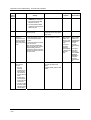
Checking HC900 Model Numbers for Compatibility
ATTENTION: Be sure to check your model numbers for compatibility before installation. For a HC900
system to be fully compatible, all components must have matching model numbers.
Each component’s model number format is XXXXXXX–XXYY-ZZ. For example, HC900 CPU is
900C71R-0000-40. For redundant CPU systems, component model numbers ZZ numbers must match. For
non-redundant CPU systems, component model numbers YY numbers must match. See examples below.
Example of a compatible redundant system
Component
Model Number XXXXXXX-XXYY-ZZ
HC900 CPU
900C71R-0000-40
Scanner 2
900C73R-0000-40
HC Designer Software
900W01-0040-40
Manuals CD
900ME1-0040-40
1042 Operator Interface
10420F-0040-40
Revision 16
10/09
HC900 Hybrid Controller Installation and User Guide
4
Introduction - Model Selection Guide
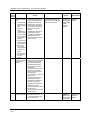
Example of a compatible non-redundant system
Component
Model Number XXXXXXX-XXYY-ZZ
HC900 CPU
900C51R-0040-00
Scanner 1
900C53R-0040-00
HC Designer Software
900W01-0040-40
Manuals CD
900ME1-0040-40
1042 Operator Interface
10420F-0040-40
Revision 16
10/09
HC900 Hybrid Controller Installation and User Guide
5
Introduction - Functional Description
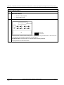
Functional Description
All Controllers
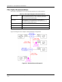
The Honeywell HC900 Hybrid Controller is an
integrated loop and logic controller that is designed
specifically for small- and medium-scale unit operations
It comprises a set of hardware and software modules that
can be assembled to satisfy any of a broad range of
process control applications. The HC900 Hybrid
Controller can consist of a single rack, as indicated in
Figure 1, or can be can be networked with other
controllers via Ethernet links to expand the dimensions
of control over a wider range of unit processes, as
indicated in Figure 2 .
Figure 1 – Small HC900 Controller Configuration
Revision 16
10/09
HC900 Hybrid Controller Installation and User Guide
6
Introduction - Functional Description
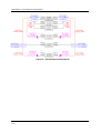
Figure 2 – Expanded HC900 Controller Configuration (C50/C70 CPU only)
The HC900 Controller design enables users and OEMs who are adept in system integration to assemble a
system that fits a broad range of requirements. Any configuration can be readily modified or expanded as
requirements dictate. In initial configuration and in subsequent modifications, the HC900 Controller
affords an optimum balance of performance and economy.
Configurations such as those shown in Figure 1 and in Figure 2, as well as many variations, can be
assembled from modular components. Many of the components are available from Honeywell, and some
are available from third-party suppliers. These modular components are available in any quantity and mix
that make the most sense for a given application.
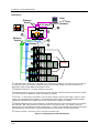
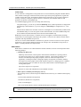
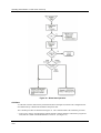
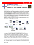
As indicated in Figure 3, the HC900 Controller includes provisions for communication via Ethernet with
host systems such as the Honeywell Experion HMI and other HMI software that supports Ethernet
Modbus/TCP protocol. Also, the communication structure of the HC900 Controller enables remote
placement of input/output components, allowing significant economies in cabling and wiring.
Revision 16
10/09
HC900 Hybrid Controller Installation and User Guide
7
Introduction - Functional Description
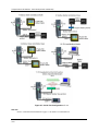
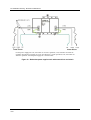
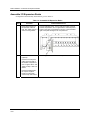
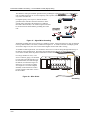
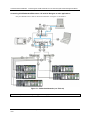
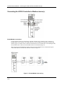
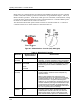
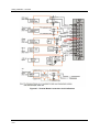
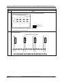
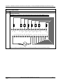
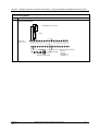
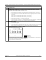
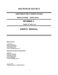
Redundancy
Vista
or 3rd Party
Software
Ethernet
Switch
10/100 base-T
5
1
3
Ethernet
Switch
A
B
100 base-T
2
6
4
4
Process
4
4
4
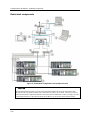
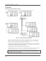
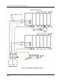
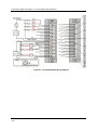
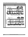
c Redundant CPUs - Redundancy is provided by two C70R CPUs operating in a controller rack; this rack has no
I/O. Each CPU has its own 100 base-T Ethernet physical communication link with one or more racks of I/O. A
Redundancy switch module (RSM) sits between the CPUs.
d Redundant CPU Power - Two power supplies for the CPUs.
e Redundant CPU-I/O connection – Each CPU has its own 100 base-T Ethernet physical communication link with
one or more racks of I/O. Multiple I/O racks require Ethernet switches.
f I/O racks –
5 racks shown, top to bottom: 4-slot w/1 power supply, 8-slot w/1 power supply, 12-slot w/1 power
supply, 8-slot w/redundant power supplies, 12-slot w/redundant power supplies. A Power Status Module (PSM) is
required with redundant power supplies. High and low capacity power supplies are available.
g Redundant Networks for Host communications - Redundant Networks for Host communications are provided on
the C70R CPU. Both network ports are continuously active on the Lead controller. The network ports on the
Reserve CPU are not available for external communications. An OPC server is available from Honeywell to support
redundant Ethernet communications and automatically transfer communications during a network failure.
h Scanner 2 module – has 2 ports, one for each CPU connection to I/O
Figure 3 – Single process with redundancies
Revision 16
10/09
HC900 Hybrid Controller Installation and User Guide
8
Introduction - Feature Summary
Feature Summary
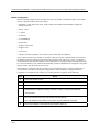
Hardware
•
Modular rack structure; components are ordered individually as needed
•
CPU with Ethernet communications
•
Easy to assemble, modify, and expand
•
Local (C30) and Remote input/output racks (C50/C70), private Ethernet-linked sub-network
•
Parallel processing - a microprocessor in each I/O module performs signal processing, to preserve update
rates
•
Power supplies - provide power to CPU rack and Scanner I/O rack
Redundancy
•
Redundant C70R CPU
•
Redundancy Switch Module (RSM) – required between redundant CPUs
•
Redundant Power Supply – provides redundant power to any CPU rack or Scanner2 I/O rack
•
Power Status Module (PSM) – required when using a second power supply in Scanner2 I/O rack
Communications
All CPUs (except where noted):
•
Two serial ports, each configurable as RS-232 or RS-485.
•
RS-232 port used for link to PC configuration tool (up to 50 feet or 12.7 meters) or modem. Port
configurable as Modbus RTU/TCP master or slave.
•
RS-485 port used for 2-wire link to the Operator Interface (up to 2000 feet or 601meters). Port
configurable as Modbus RTU master or slave.
•
Ethernet 10/100Base-T connection to: up to 5 PC hosts via Modbus/TCP protocol, Peer-to Peer
communication with other HC900 Controllers, and the Internet. C70 has 2 Ethernet ports for connection
to up to 10 PC hosts. It also supports Modbus/TCP Initiator function over both ports.
•
Private Ethernet 100Base-T connection to I/O expansion racks (except C30 CPU)
Redundancy
•
Supervisory Network – Ethernet 10/100 baseT to PC Applications (HC Designer & HC Utilities),
communicates to peer HC900 Controllers over Ethernet. C70R has two Ethernet ports. Lead C70R CPU
supports up to 10 concurrent sockets. It also supports Modbus/TCP Initiator function over both ports.
•
I/O Network – Direct connection to each C70R CPU.
•
Device Network – RS-232 or RS-485 Serial Interface; Modbus RTU. Two serial ports available. Each
port can be set as Modbus Master or Slave. Host Serial Interface for Honeywell or third party operator
interface.
For more information
For complete feature summary and specifications see Specifications on page 190.
Revision 16
10/09
HC900 Hybrid Controller Installation and User Guide
9
Components and Architecture
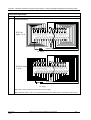
Overview
This section provides a description of each of the major components that can be included in an HC900
Controller physical configuration, and indicates some of the methods by which they can be combined.
Components
The Honeywell HC900 Hybrid Controller includes a set of hardware modules that can be combined and
configured as required for a wide range of small to medium process control applications.
Some of the modules are required in all configurations. Others are optional; they are selected as
appropriate to provide optional functions and/or to "size" the system, either in initial planning, or in
modifying and/or expanding the system to meet changing requirements.
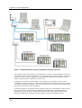
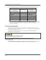
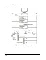
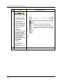
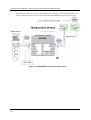
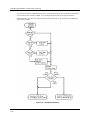
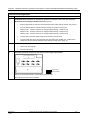
An HC900 Controller configuration with multiple controllers is illustrated in Figure 4. This illustration
includes key-numbers that identify components that are described in Table 1.
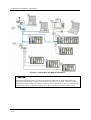
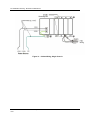
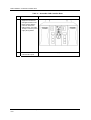
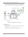
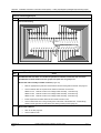
An HC900 Redundant Controller configuration with multiple I/O racks is illustrated in Figure 5. This
illustration includes key-numbers that identify components that are described in Table 2.
Communications lockout is possible in high network traffic conditions.
Extraneous traffic is possible when sharing bandwidth with other devices. We recommend putting the
controller on a private network segment. Failure to do so could, in high traffic cases, result in
communications lockout requiring the controller to be power-cycled.
Revision 16
10/09
HC900 Hybrid Controller Installation and User Guide
10
Components and Architecture - Components
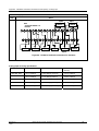
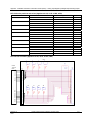
Figure 4 – Configuration with Multiple Controllers
The HC900-expansion I/O link is a private network and the switch used for the interconnection of the
HC900 Processor and Scanners must not be connected to any other LAN or WAN. Likewise, no devices
other than the HC900 components should be connected to the I/O link Switch. Failure to comply will cause
communication failures on the I/O link causing I/O modules to go in and out of their failsafe settings.
Revision 16
10/09
HC900 Hybrid Controller Installation and User Guide
11
Components and Architecture - Components
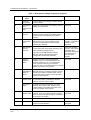
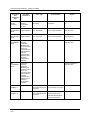
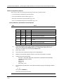
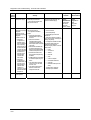
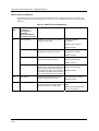
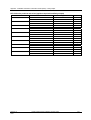
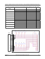
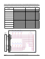
Table 1 – Descriptions of Major Components (Figure 4)
Key No.
Component
Name
Description
Source
1
Controller
(Local) Rack
Includes: Rack, Power Supply, Controller Module,
and I/O modules
Honeywell
2
I/O Expansion
Rack
(C50/C70 CPU
only)
(Optional) Includes: Rack, Power Supply, Scanner
Module, and I/O modules
Honeywell
3
Operator
Interface
(Optional) link to RS-485 port on a Controller
Module; provides operating and utilities displays.
Includes buttons and (optional) AT-keyboard
interface.
Honeywell
4
PC
Configuration
Tool
(Optional) PC (laptop or desktop) connects to
RS-232 port on any (one) Controller module.
Includes Honeywell Hybrid Control Designer
(configuration software).
PC is from third-party
supplier. Configuration
software is from
Honeywell.
5
HMI (HumanMachine
Interface)
(Optional) PC link to Ethernet network, which may
include other HMIs, other HC900 Controllers, and
other networks (including Internet).
PC is from third-party
supplier. HMI software
is available from
Honeywell (PlantScape
or SpecView32) or
from third-party
supplier.
Typically includes HMI operating software.
May also include Hybrid Control Designer
(configuration tool and utility software).
6
Ethernet
100Base-T
Switch
Enables connection of the private Ethernet
100Base-T port on a Controller Module to the
Scanner modules on 2, 3, or 4 I/O Expansion
racks. (C50/C70 CPU only) (If a single I/O
expansion rack is connected directly to a Controller
Module, the Switch is not required.)
Honeywell
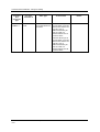
6a
Ethernet
10/100Base-T
Switch or
Router
Enables inter-connection of several 10/100Base-T
Ethernet devices in an Ethernet network. Devices
include other HC900 Controllers, HMIs, and can
also include routers, brouters, servers, and other
devices in wider networks.
Third-party suppliers.
7
Ethernet CAT5
shielded cable
Connects I/O expansion racks (C50/C70 CPU only)
to controllers and/or to 10/100baseT Ethernet
switches. 10’or 20’ (3.04 or 6.08m)
Third-party suppliers or
Honeywell
Fiber Optics
Cable
Controller to remote rack distance up to 750m
(2460 ft.) with one fiber cable. Distances up to
1500m (4920 ft.) are possible with a fiber switch
used as a repeater at the midpoint.
8
Ethernet CAT5
shielded cable
Connects devices in Ethernet Open Connectivity
network. Cross-over cable is used for Controllerto-PC connection; straight-through for Controller-toe connection. 20’ (6.08m).
Third-party suppliers or
Honeywell
9
RS-485 cable
Belden #9271 or equivalent, up to 2000’ (601m).
Third-party suppliers
10
RS-232 cable
Null modem cable, up to 50’ (15.24m) (PC modem
cable if used with Modems.)
Third-party suppliers or
Honeywell
Revision 16
10/09
HC900 Hybrid Controller Installation and User Guide
12
Components and Architecture - Redundant components
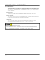
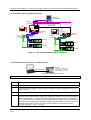
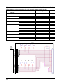
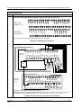
Redundant components
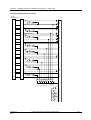
Figure 5 – Redundant Configuration with multiple I/O racks
The HC900-expansion I/O link is a private network and the switch used for the interconnection of the
HC900 Processor and Scanners must not be connected to any other LAN or WAN. Likewise, no devices
other than the HC900 components should be connected to the I/O link Switch. Failure to comply will cause
communication failures on the I/O link causing I/O modules to go in and out of their failsafe settings.
Revision 16
10/09
HC900 Hybrid Controller Installation and User Guide
13
Components and Architecture - Redundant components
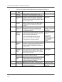
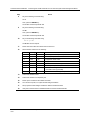
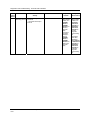
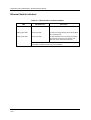
Table 2 – Descriptions of Major Redundancy Components (Figure 5)
Key No.
Component
Name
Description
Source
1
Controller
(Local) Rack
Includes: Rack, 2 Power Supplies, 2 C70R
Controllers, 1 Redundancy Switch Module (RSM)
Honeywell
2
I/O Expansion
Rack
Includes: 1 Scanner 2 module, 1 Power Supply,
and up to 4, 8, or 12 I/O modules. Optional second
Power Supply and Power Status Module (PSM) on
8- and 12-slot I/O racks.
Honeywell
3
Operator
Interface
(Optional) link to RS-485 port on a Controller
Module; provides operating and utilities displays.
Includes buttons and (optional) AT-keyboard
interface.
Honeywell
4
PC
Configuration
Tool
(Optional) PC (laptop or desktop) connects to
RS-232 port on any (one) Controller module.
Includes Honeywell Hybrid Control Designer
(configuration software).
PC is from third-party
supplier. Configuration
software is from
Honeywell.
5
HMI (HumanMachine
Interface)
(Optional) PC link to Ethernet network, which may
include other HMIs, other HC900 Controllers, and
other networks (including Internet).
PC is from third-party
supplier.
Typically includes HMI operating software.
May also include Hybrid Control Designer
(configuration tool and utility software).
HMI software is
available from
Honeywell (PlantScape
or SpecView32) or
from third-party
supplier.
6
Ethernet
100Base-T
Switch
Required if using 2 or more I/O Expansion racks.
Provides connection of the I/O Ethernet 100Base-T
port on a Controller Module to the Scanner
modules. Switch not required for connection to a
single I/O rack.
Honeywell
6a
Ethernet
10/100Base-T
Switch or
Router
Enables inter-connection of several 10/100Base-T
Ethernet devices in an Ethernet network. Devices
include other HC900 Controllers, HMIs, and can
also include routers, brouters, servers, and other
devices in wider networks.
Honeywell or thirdparty suppliers.
7
Ethernet CAT5
shielded cable
Connects I/O expansion racks to controllers and/or
to 10/100baseT Ethernet switches.
Third-party suppliers or
Honeywell
Fiber Optics
Cable
Controller to remote rack distance up to 750m
(2460 ft.) with one fiber cable. Distances up to
1500m (4920 ft.) are possible with a fiber switch
used as a repeater at the midpoint.
8
RS-485 cable
Belden #9271 or equivalent, up to 2000’ (601m).
Third-party suppliers
9
RS-232 cable
Null modem cable, up to 50’ (15.24m) (PC modem
cable if used with Modems.)
Third-party suppliers or
Honeywell
Revision 16
10/09
HC900 Hybrid Controller Installation and User Guide
14
Components and Architecture - Hardware Components
Hardware Components
This section contains general descriptions of each of the major components of the HC900 system. For
environmental specifications, refer to the section on Pre-Installation Planning.
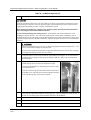
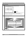
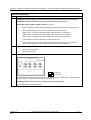
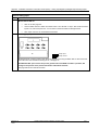
HC900 Controller Rack
An HC900 Controller ("local rack") is shown in Figure 6. As indicated in this figure, the Controller Rack
includes:
1. Rack, available in 4- 8-, or 12-slot versions
2. Power Supply
3. Controller Module
4. Grounding bars (for I/O wiring;
optional)
5. Input/Output modules.
6. I/O Terminal Blocks
Figure 6 – Controller Rack Components
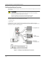
HC900 Redundant Controller Rack
A HC900 Redundant Controller is shown in Figure 7.
1. Rack
2. Redundancy Switch Module (RSM) . Interface
between Lead/Reserve controllers.
3. Lead/Reserve controllers. Two C70R CPUs,
designated “CPU-A” (left), “CPU-B” (right).
4. Two Power Supplies.
Figure 7 – Redundant Controller Rack Components
Revision 16
10/09
HC900 Hybrid Controller Installation and User Guide
15
Components and Architecture - Hardware Components
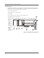
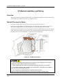
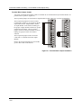
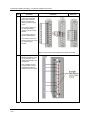
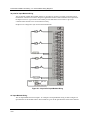
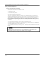
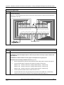
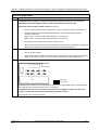
I/O Expansion Rack
I/O expansion ("remote") racks, shown in Figure 8, are available to accommodate additional input/output
modules, and/or to enable location of I/O modules close to the process and remote from the controller. For
C70R, all I/O is in a rack or racks separate from the controller rack.
An I/O expansion rack includes:
1. Rack, available in 4- 8-, or 12-slot versions
2. Power Supply
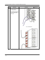
3. Scanner 1 Module (C50/C70) (shown) or Scanner 2 Module (C70R)
4. Grounding bars (for I/O wiring; optional)
5. Input/Output modules
6. I/O Terminal
Blocks
7. Power Status
Module
(PSM)
(req’d if using
Reserve
Power Supply)
8. Reserve Power
Supply
(optional).
Available in 8- or 12slot racks.
Figure 8 – I/O Expansion Rack Components
Revision 16
10/09
HC900 Hybrid Controller Installation and User Guide
16
Components and Architecture - Hardware Components
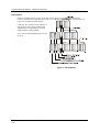
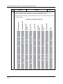
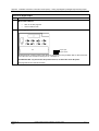
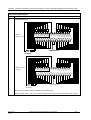
Rack Options
Racks are available in 4-slot, 8-slot, and 12-Slot versions. Racks are interchangeable between the
Controller rack and an I/O expansion rack (C50, C70, C70R CPU only), and all three versions shown in
Figure 9 are available for either purpose.
C70R only: I/O rack has Scanner 2 Module. 8
and 12 slot I/O racks can be modified with
additional slots for optional Reserve Power
Supply and Power Status Module.
Note: You can install redundant power on any
I/O rack.
Figure 9 – Rack Options
Revision 16
10/09
HC900 Hybrid Controller Installation and User Guide
17
Components and Architecture - Hardware Components
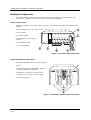
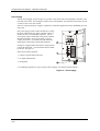
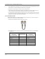
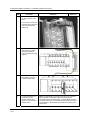
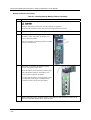
Power Supply
The P01 Power Supply, shown in Figure 10, provides 5 Vdc and 24 Vdc to the backplane connectors in the
local and remote racks. Power Supply is used in each Controller Rack, I/O expansion racks and for all rack
versions (4-slot, 8-slot, and 12-Slot).
The lower capacity P02 power supply is available for reduced I/O applications and for Redundant processor
rack power.
P24 power supply provides 5VDC and 24VDC to satisfy
the power requirements of a single controller with I/O, a
Remote I/O rack or a Redundant C70R CPU. The 60
watt capacity requires minimal de-rating of the available
HC900 I/O modules. A tool-secured door covers the
voltage connections. An internal non-replaceable fuse
limits supply current under certain fault conditions.
Each power supply includes an internal 5.0-amp fuse that
is not field-replaceable. (An external fuse may be added
by the user. See page 61.)
Items shown with key numbers:
1. Voltage test points (P01model only)
2. AC Input terminal block
3. Wiring label
4. Grounding lug (Reference; lug is not part of Power Supply; it is staked to bottom of Rack.)
Figure 10 – Power Supply
Revision 16
10/09
HC900 Hybrid Controller Installation and User Guide
18
Components and Architecture - Hardware Components
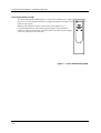
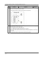
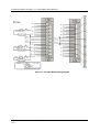
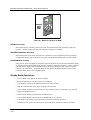
Power Status Module (C70R)
The Power Status Module (PSM) (Figure 11) sits between redundant power supplies on the I/O rack (see
page 16). It is a status module for both power supplies and indicates which are in use, PS-1 (left) or PS-2
(right) or both (typical).
When the status indicator for either or both of the power supplies is lit, it
is reporting that the status of the associated power supply is good and that the
outputs are with in specified limits. When the status is off, either the power supply
is off or the voltages are out of tolerance.
Figure 11 – Power Status Module (PSM)
Revision 16
10/09
HC900 Hybrid Controller Installation and User Guide
19
Components and Architecture - Hardware Components
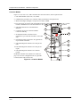
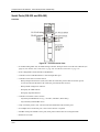
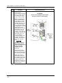
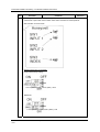
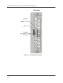
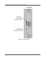
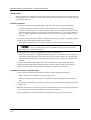
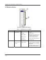
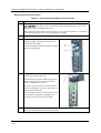
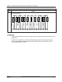
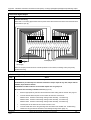
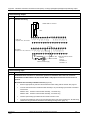
Controller Module
Figure 12. C30, C50, C70, C70R Controllers share the same features, with exceptions noted.
1. CPU model number (C30, C50, C70, C70R).
2. Lithium battery (beneath cover), which is readily accessible for field replacement.
3. Mode switch (Pgm, Run/Pgm). Not present on C70R; see RSM.
4. Two serial ports, S1 and S2, each configurable as RS-232 or RS-485. RS-232 interfaces to PC, external
CXXX
modem or Modbus devices. RS-485 interfaces to PC, Operator
1 Interface or Modbus devices/host.
5. LED status indicators for communications
functions.
6. Connection to I/O port of Scanner Module.
C50/C70/C70R only.
7. Second Ethernet Host Connection to PC
applications or peer HC900 controllers. C70/C70R
only.
11
2
3
Run/Pgm
S1
S2
9. LED status/diagnostic indicator for serial port S2
(left).
11. LED status/diagnostic indicator for controller
module.
Run
4
8. First Ethernet Host Connection to PC applications
or peer HC900 controllers.
10. LED status/diagnostic indicator for serial port S1
(right).
10
Run/Pgm
Pgm
5
Redundant controller rack contains two C70Rs (see
page 15). Left CPU is designated CPU-A, right CPU
is CPU-B; either CPU can be Lead.
9
E1
8
E2
7
I/O
6
Figure 12 – Controller Module
Revision 16
10/09
HC900 Hybrid Controller Installation and User Guide
20
Components and Architecture - Hardware Components
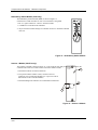
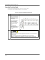
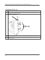
Redundancy Switch Module (C70R only)
The Redundancy Switch Module (RSM) is shown in Figure 13.
It sits between C70R controllers on rack. Left Controller is designated
“CPU-A”; right Controller is “CPU-B.” Features include:
1. Lead/Reserve controller status indicators.
2. Keyed switch for manual changes to controller modes or to facilitate a Manual
Fail Over.
Figure 13 – Redundancy Switch Module
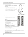
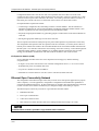
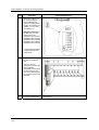
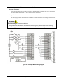
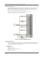
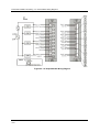
Scanner 1 Module (C50/C70 only)
The Scanner 1 Module is shown in Figure 14. It sits in the I/O rack and provides the link between the
controller and remote I/O. Features at the front of the module include:
SCANNER
1
1 PORT
1. LED status indicator for scanner functions.
2. One private Ethernet 10Base-T Port; connects to the I/O
expansion port on Controller Module (or to a port on a Switch
that connects to the Controller Module)
3. LED status/diagnostic indicators for communications functions.
2
I/O
3
Figure 14 – Scanner 1 Module
Revision 16
10/09
HC900 Hybrid Controller Installation and User Guide
21
Components and Architecture - Hardware Components
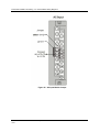
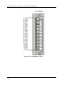
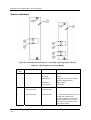
Scanner 2 Port Module (C70R only)
The Scanner 2 Port Module is shown in Figure 15. The dual ports
provide redundancy through the 2 CPUs. Features at the front of the
module include:
1. LED status/diagnostic indicator for scanner functions.
2. I/O port A. Private Ethernet 10Base-T Port. Connects directly to
I/O port on CPU-A (or indirectly through a switch).
3. I/O port B. Private Ethernet 10Base-T Port. Connects directly to
I/O port on CPU-B (or indirectly through a switch).
4. LED status/diagnostic indicators for communications functions
Figure 15 – Scanner 2 Module
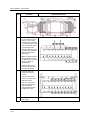
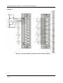
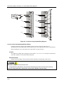
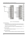
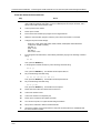
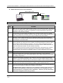
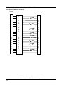
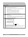
Input/Output Modules
I/O module types:
•
16 point high level analog input module: each point is
configurable for V or mA. Point-to-point isolation.
•
4 point isolated analog output module: Supports from 0 to
20mA each.
•
8 or 16 point analog output module: Supports from 0 to 20mA
each. Isolated in groups of 4 channels.
•
16 point digital input modules: Contact closure type, DC
voltage and AC voltage types.
•
32 point digital input module: DC voltage.
•
8 point AC or 16 point DC digital output modules (sinking
type).
•
32 point digital output: DC voltage (sourcing type)
•
8 point relay output module: four form C type and four form A type relays.
•
8 point Universal Analog Input module
•
4 channel Pulse/Frequency/Quadrature I/O module
Figure 16 – I/O Module Terminal Blocks
Each I/O module includes a status indicator for the module. Digital Input and Digital Output modules also
include a status indicator for each channel. Terminal blocks available include the Euro style (Figure 16
left) and the Barrier style (Figure 16 right).
For more information on I/O modules and associated terminal blocks, refer to the section in this manual on
Input/Output Installation and Wiring.
Revision 16
10/09
HC900 Hybrid Controller Installation and User Guide
22
Components and Architecture - Hardware Components
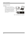
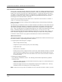
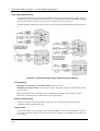
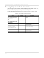
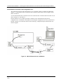
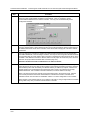
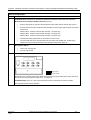
Personal Computer
A Personal Computer is required for creating the control and data acquisition strategy (configuration file)
that runs in the controller, using the Hybrid Control Designer configuration software. The PC can also be
used to download/upload configuration files to/from the controller, and can be used to download program
updates to firmware in the Controller Module and/or Scanner Modules.
A PC can be connected to the controller via the RS-232 Port on the Controller module, and can also be
networked to the controller via the Ethernet 10/100Base-T Open Connectivity Network port.
Redundant controllers: PC communicates with Lead Controller only.
NOTE: For specific PC requirements and for specific software requirements, refer to the Hybrid Control
Designer Users Manual.
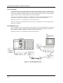
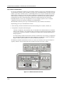
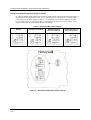
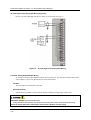
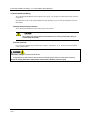
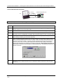
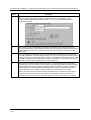
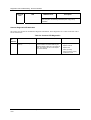
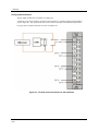
RS-232 Modem Devices
The PC configuration tool connects from the RS-232 serial port of the Controller Module to a serial port on
the PC. (Figure 17) The PC can be located remote from the Controller by using Modems and telephone
links. Modems and suitable cabling are available from third-party vendors.
Redundant controllers: PC communicates with Lead controller only.
Figure 17 – RS-232 Modem Devices
Revision 16
10/09
HC900 Hybrid Controller Installation and User Guide
23
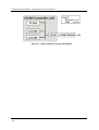
Components and Architecture - Ethernet Devices/Considerations
Ethernet Devices/Considerations
Ethernet device requirements vary with specific applications. Regarding intended use, however, they fall
into two categories:
•
The HC900-expansion I/O link is a private network and the switch used for the
interconnection of the HC900 Processor and Scanners must not be connected to any other LAN or
WAN. Likewise, no devices other than the HC900 components should be connected to the I/O link
Switch. Failure to comply will cause communication failures on the I/O link causing I/O modules to go
in and out of their failsafe settings.
•
Revision 16
10/09
Components of the Ethernet Open Connectivity Network, which links an HC900 Hybrid Controller to
Peers, to HMI Supervisory Stations, and to other Ethernet 10/100Base-T devices that support TCP/IP.
The Ethernet Open connectivity Network is potentially more complex than the I/O expansion network,
and in some cases, may require the services of an IT networking professional.
HC900 Hybrid Controller Installation and User Guide
24
Components and Architecture - I/O Network
I/O Network
I/O Expansion Network (C50/C70 CPU only)
Examples of HC900 Controller I/O expansion configurations are shown in Figure 18.
Figure 18 – HC900 Controller Configurations
In Figure 18, any of the racks shown in each controller configuration can be 4-, 8-, or 12-slot versions.
The Ethernet cables for the I/O expansion links are standard shielded Cat 5 cables, with standard RJ45
connectors. Each cable segment can be up to 100 meters (328 feet) long.
You can also use fiber optic cable for connections between the controller and a remote rack. Distances up
to 750m (2460 ft.) are possible with one fiber cable. Distances up to 1500m (4920 ft.) are possible with a
fiber switch used as a repeater at the midpoint. (See page 200)
Configuration 1 is the C50/C70 CPU with I/O but no I/O expansion racks.
Configuration 2 shows the C50/C70 CPU with 1 I/O expansion rack. The Ethernet cable connects directly
between the 10Base-T connectors on the C50 CPU Controller Module and the Scanner Module.
Attention: For 2 or more I/O expansion racks a switch is required. Use only Honeywell
recommended switches (part no. 50008930-001). The total number of switches is limited to 2 in
series between a CPU and its scanners.
Revision 16
10/09
HC900 Hybrid Controller Installation and User Guide
25
Components and Architecture - Ethernet Open Connectivity Network
Configuration 3 shows the C50/C70 CPU with 3 I/O expansion racks. Since there are at least 2 I/O
expansion racks a switch is required. When an Ethernet switch is used to connect to expansion I/O, a cable
goes between the I/O port on the controller to the switch. Two cables go from the switch to 2 scanners. A
third cable goes from the switch to a second switch, which connects to a third remote scanner.
I/O implementation requirements include:
•
Constructing a configuration file, and loading it into the Controller Module. This file includes I/O
numbering assignments for each I/O Function Block regarding Rack Number, Module Number ("slot"
number, or position in the rack, starting from the left), and Channel Number.
•
Physically assigning Rack Numbers, by positioning jumpers or DIP switches in the Scanner Module for
each rack.
•
Placing the appropriate module type in each slot in each rack.
The I/O expansion network uses Honeywell private protocol that optimizes I/O performance and security.
The configuration and operation of the I/O expansion network is automatic, it is entirely under control of
built-in private software that resides in the Controller Module and in each Scanner Module included in the
HC900 system. The controller examines the control strategy stored in its memory, verifies that the physical
configuration (Rack Numbers, and I/O Module type- by Module Number) matches the stored control
strategy, and establishes communication with each of the I/O modules in each of the I/O racks.
I/O Expansion Network (C70R)
I/O for redundant controllers is the same as I/O Expansion Network page 25, with the following
exceptions/notes.
•
In Figure 18, any of the racks shown in each controller configuration can be 4-, 8- or 12-slot versions.
Redundant I/O power not available with 4-slot.
•
I/O ports are 100 Base-T instead of 10Base-T.
•
Maximum of 2 switches between each CPU (CPU A and CPU B) and the I/O racks.
Ethernet Open Connectivity Network
The configuration of the Ethernet Open Connectivity Network varies with specific applications in purpose
and in complexity. In some applications, configuration is straightforward and within the capabilities of
experienced installation technicians. In other applications (for example, those that include inter-connection
to other networks such as Intranet and Internet), a working knowledge of networking is required.
The Ethernet Open Connectivity Network for a given HC900 Controller enables:
•
Redundant Networks.
•
Peer-to-peer communication
•
Connection to other PC hosts
•
Inter-connection to other networks (such as for sending Alarm/Event messages via e-mail.)
Communications lockout is possible in high network traffic conditions.
Revision 16
10/09
HC900 Hybrid Controller Installation and User Guide
26
Components and Architecture - Ethernet Open Connectivity Network
Extraneous traffic is possible when sharing bandwidth with other devices. We recommend putting the
controller on a private network segment. Failure to do so could, in high traffic cases, result in
communications lockout requiring the controller to be power-cycled.
Redundant Networks
Honeywell OPC Server supports redundant networks. Up to 10 connections may be distributed in any
combination across the controller’s 2 network ports (E1 and E2). PC hosts may include, for example, HMI
supervisory software and/or Hybrid Control Designer configuration software. Redundant ports may be used
in a simplex mode (non-redundant).
Revision 16
10/09
HC900 Hybrid Controller Installation and User Guide
27
Components and Architecture - Ethernet Open Connectivity Network
Peer-to-Peer Communication
Peer-to-peer communication enables any given HC900 Controller to request a peer relationship with up to
32 other HC900 Controllers; other controllers can request a peer relationship with the controller. The total
number of peers that a controller can have a relationship with is 32. Peer-to-peer communication uses the
Ethernet Open Connectivity network and employs standard User Datagram Protocol (UDP) for fast and
efficient transfer of information. Peer-to-peer communication is based on fail-safe and data expiration
mechanisms that provide for fault and loading considerations without requiring reserved network
bandwidth allocation. Peer-to-peer is designed to be easy to configure as part of a device’s standard
configuration and does not require the distribution of a global database.
With redundant controllers, peer-to-peer communication always stays with the Lead controller.
Implementing peer-to-peer communications involves:
• Interconnecting controllers with Ethernet media and networking devices (cables, switches, etc)
• Configuration (via Hybrid Control Designer):
−
Controller configuration, which includes entry of an IP address and a Subnet Mask, and a Controller
Name for each controller. (The Controller Name is used only by the Honeywell proprietary software
for network access between controllers; it should not be confused with a Network Domain Name or
Workgroup Name.)
−
Peer Data Exchange (PDE) function blocks, which are included in the control strategy (configuration
file). PDE function blocks include PDE Control, PDE Write, and PDE Read. (Refer to the HC900
Hybrid Controller Function Block User Guide for additional information.)
An illustration of HC900 Controller Peer-to-Peer on a Local Area Network (LAN) is given in Figure 19.
Typically, a Router is used for interconnection to another network (LAN, WAN, or other).
Figure 19 – Modular Network Structure
Revision 16
10/09
HC900 Hybrid Controller Installation and User Guide
28
Components and Architecture - Ethernet Open Connectivity Network
Connection to PC Hosts
Connection to PC hosts (for example, PCs that include HMI supervisory software and/or Hybrid Control
Designer configuration software) can be via Modbus/TCP as well as serial Modbus RTU over either the
RS-485 or RS-232 communications ports. Both ports support Modbus RTU and are configurable as master
or slave. The 5 TCP hosts can be concurrent with Modbus hosts on one or both of the other ports. Any
given controller is capable of concurrent communication with up to five PC hosts. (The meaning of the
term “host” varies, but for this definition, a PC host is any PC that is on the same LAN as the controller, or
on any LAN or WAN (Wide Area Network) that is network-connected to the controller.
Each HC900 Controller has five “sockets” (software and memory resources), each of which can service
data requests from any networked PC on a client (host)/server (controller) basis. C70R has 10 sockets. The
sockets are available on a first-come, first-served basis. Typically, when the data service for any PC Host
request is completed or times out, it allows the socket to become available to any other PC Host in the
hierarchy of networks.
Note: PDE communications, discussed previously, do not use the PC host connection sockets. PDE
communications are separate from (and are transmitted concurrent with) PC host-to-controller
communications.
The PC host can include software that closely relates to and supports controller functioning and can also
include other software that is related remotely or not at all. Closely related software can include:
Either
Hybrid Control Designer – for generating and managing configuration files,
Or
HMI (Supervisory/Data Acquisition Software) or Operator Panel with Modbus/TCP driver
Or
Both configuration and HMI software (and or panel)
All communications between a controller and a PC host use Open Modbus/TCP protocol, whose
widespread use is making it an industry standard. Modbus/TCP is basically an adaptation of the Modbus
messaging structure that uses TCP/IP for a message carrier. In general, Modbus messaging is available
in two versions: ASCII, in which each eight-bit byte is sent as 2 ASCII characters, and RTU, in which
each byte is sent as two four-bit hexadecimal characters. Each Modbus message frame is embedded into
a TCP/IP datagram as indicated in Figure 20.
Figure 20 – Modbus/TCP Framing
The HC900 Controller uses either Modbus/TCP or Modbus RTU, not ASCII. The Modbus mapping
structure for the HC900 Controller is based on the mapping structure employed in Honeywell’s UMC800
Controller, and the function codes and methods for parameter access are also virtually identical.
Revision 16
10/09
HC900 Hybrid Controller Installation and User Guide
29
Components and Architecture - Ethernet Open Connectivity Network
Modbus Maps
In your controller’s configuration certain parameters are each automatically assigned a Modbus address.
These include certain types of function blocks (such as loops and set point programmers), signals and
variables, among other items. Through their addresses these parameters can be accessed or displayed
remotely, such as by a third-party operator interface. Collectively, these Modbus addresses and
parameters are known as the Modbus map.
Two Modbus Mapping options exist: Fixed map and Custom map
Using HC Designer, you can use a pre-defined fixed map where common parameters are mapped out
automatically at fixed addresses, or you can configure a custom map for configurations rev. 4.0 or
higher.
Function blocks added to the controller in release 4.0 and higher are not automatically included in the
Fixed Modbus Map. To access the registers of these function blocks, the Custom Modbus Map must
be used and the block data manually inserted into the custom Modbus map.
HMI Supervisory/SCADA software is available from various suppliers, and functionality and setup
requirements vary with suppliers and with specific products. In all cases, the software selected must be
compatible with Open Modbus/TCP protocol.
The user can use the standard Modbus command set to generate a custom set of drivers for his specific
application, or may purchase additional software (for example, OPC with Modbus /TCP protocol) to
reduce or virtually eliminate development tasks.
HMI software
HMI software available for use with the HC900 Controller includes, but is not necessarily limited to the
following packages.
•
•
available from Honeywell
−
Plantscape Vista Software, which operates under Windows 2000/XP Pro operating software,
provides PC-based supervisory control and data acquisition. This package includes a large
selection of standard operating display templates, which can reduce development time
significantly. PlantScape includes a full graphic display development environment, enabling
development of custom graphics that include animated responses to changing process conditions.
A batch reporting option is available in release 400, which includes a standard template for
creating batch reports.
−
SpecView32 (SpecView Corporation)
−
OPC Server (works with redundant and non-redundant networks)
Other software (available from third-party sources)
The following software, which incorporates Modbus/TCP connectivity, is available from third-party
sources:
− The
Fix Family (Intellution Incorporated)
− Wonderware
− Citect
− OPC
(Wonderware Corporation)
(CI Technologies)
server/client software (various; available from Kepware and others)
Note: The items in this list are not sold by Honeywell. They have not all been tested and certified by
Honeywell, and are not necessarily recommended or endorsed by Honeywell for any specific use.
Revision 16
10/09
HC900 Hybrid Controller Installation and User Guide
30
Components and Architecture - Ethernet Open Connectivity Network
Inter-Connection to Other Networks
In many cases, an HC900 Controller application will include a single, free-standing controller that involves
no connections via the Ethernet Open Connectivity network. In other cases, the HC900 Controller will be a
member of a Local Area Network (LAN) as indicated in Figure 19. The HC900 controller LAN may be
very simple, or it may include many devices in a complex and very sophisticated structure. In any case, it
must always be regarded as a single, modular entity that can be protected from intrusion by any other
networking device to which this LAN is connected.
Various types of networking devices that enable selective connection to other networks are available. A
“Router” is commonly used for this purpose.
Routers can examine and “filter” message packets, permitting passage of wanted messages and denying
passage of all others.
The feature that gives the Router its name is it enables translation of IP addresses, which enables networks
with dissimilar network IP addresses to communicate as though they were members of the same network.
This feature is particularly useful when an HC900 Controller LAN is installed under “local addressing
rules”. That is, IP addressing can be assigned without approval of or conflict with world Internet governing
bodies. A default IP address is provided in each C30 and C50 CPU: 192.168.1.254. Later, when
connecting to networks with more stringent addressing requirements, it is necessary only to configure the
Router with address mapping and connect it between the existing LAN and the other existing network.
Connections to other networks vary in purposes and methods; some of these are described below.
E-Mail Communications
The HC900 Controller includes e-mail software that enables communication of Alarms and Events to up to
three Internet addresses. Implementing this feature consists of:
• Using the Hybrid Control Designer to configure:
− Alarm Groups and Event Groups
− Assignment of specific alarms to priority and e-mail enabling
− E-Mail address lists
− SMTP mail server IP address
− Default gateway must be configured in order to send e-mail. With redundant controllers, two default
gateways need to be configured; one for each of the redundant networks (assuming both are being
used). This will typically be the LAN side IP address of the routers used to connect the controller to
the external network.
• Installing and configuring hardware
Note: This data is included for reference. The following items should be implemented by qualified
IT/MIS personnel.
− Install and configure a Router to provide isolation and security. (Figure 21) (This should be part of
standard network installation.)
− Install and configure internet access to Simple Mail Transport Protocol (SMTP) server. This may
include the location of an existing server on an existing network.
Note: Consult your service provider for availability of access to network, local cable, or DSL in your area.
Revision 16
10/09
HC900 Hybrid Controller Installation and User Guide
31
Components and Architecture - Ethernet Open Connectivity Network
Figure 21 – Typical installation using a Cable Modem
Revision 16
10/09
HC900 Hybrid Controller Installation and User Guide
32
Components and Architecture - Serial Ports (RS-232 and RS-485)
Serial Ports (RS-232 and RS-485)
Overview
Figure 22 – Controller Serial Ports
•
S1 default setting is RS-232; S2 default setting is RS-485. Each port can be set to RS-232 or RS-485 (see
page 35). For RS-232 cable connections see page 120. For RS-485 connections see page 137.
•
Ports configurable as ELN (default) or Modbus RTU.
•
Controller can act as Modbus master or slave through either port.
•
Controller can be slave to masters such as
•
−
Honeywell Operator Interface (1040, 559). Must be on RS-485 port S2. Will not work on port S1
even if set to RS-485. Will not work on RS-232 port with 232/485 converter.
−
Honeywell HC Designer PC software
−
Third party PC HMI software
−
Third party Operator Interface
Controller can master to slaves such as
−
Any Honeywell Modbus device (e.g., recorders, controllers, flame safety)
−
Any non-Honeywell Modbus device.
•
Only one master port at a time, can’t have RS-232 and RS-485 both as master ports.
•
For multiple slaves on RS-232 port, a 232-to-485 converter is required.
•
Modbus master ports default to slave ports, ELN protocol when CPUs are in Program mode.
•
Baud rates to 57,600
Revision 16
10/09
HC900 Hybrid Controller Installation and User Guide
33
Components and Architecture - Serial Ports (RS-232 and RS-485)
Setting serial ports S1 and S2 to RS-232 or RS-485
S1 serial port default setting is RS-232; S2 serial port default setting is RS-485 terminated. Functionality is
determined by DIP switch setting on SW1 (for S1) and SW2 (for S2). See Figure 23. To change either
port’s setting, use the switch settings in Table 3. Use a small slotted screwdriver or paperclip to gently
move the DIP switches. If you push too hard you could damage the switches or nearby circuitry. Avoid
using pencils because the point could break and cause damage.
Table 3 – Serial port DIP switch settings
RS-232
RS-485 unterminated
RS-485 terminated
(last link in network)
RS-485 with external
bias, unterminated
Figure 23 – Serial Ports DIP Switch default settings
Revision 16
10/09
HC900 Hybrid Controller Installation and User Guide
34
Components and Architecture - Serial Ports (RS-232 and RS-485)
Simultaneous port configurations
Figure 24, Figure 25 and Table 4 show the ways the CPU’s two serial ports can be configured
simultaneously.
The referenced figures show the C30 but any controller can be used. Port S2 (left side) is RS-485 by
default; port S1 (right side) is RS-232 by default.
Be sure to make RS-485 connections to both CPU-A and CPU-B of redundant controllers having C70R
CPUs.
Do not make RS-232 connections to both CPU-A and CPU-B of redundant controllers.
Table 4 – Simultaneous serial port configurations
See
Figure 24 #1
RS-232 Port Configured as
RS-485 Port configured as
ELN device*
ELN device*
Figure 24 #2
Controller is Modbus Slave
ELN device*
Figure 24 #3
ELN device*
Controller is Modbus Slave
Figure 24 #4
Controller is Modbus master to multiple
slaves**
ELN device*
Figure 24 #5
Controller is Modbus Master to single slave
ELN device*
Figure 24 #6
Controller is one of multiple Modbus slaves**
ELN device*
Figure 25 #7
Controller is Modbus slave
Controller is Modbus master to multiple
slaves
Figure 25 #8
Controller is Modbus master to multiple
slaves
Controller is Modbus slave
Figure 25 #9
Controller is Modbus slave
Controller is Modbus slave
Figure 25 #10
ELN device*
Controller is Modbus master to multiple
slaves
Figure 25 #11
Controller is Modbus slave via modem
ELN device*
*Such as Honeywell HCDesigner configuration software running on a PC or Honeywell 1040/559 Operator Interface
**Requires RS-232-RS-485 converter
Revision 16
10/09
HC900 Hybrid Controller Installation and User Guide
35
Components and Architecture - Serial Ports (RS-232 and RS-485)
Figure 24 – Serial Port Configurations 1 – 6
Revision 16
10/09
HC900 Hybrid Controller Installation and User Guide
36
Components and Architecture - Serial Ports (RS-232 and RS-485)
Figure 25 – Serial Port Configurations 7 – 11
See also
Refer to Communications Installation on page 113 for details on communications.
Revision 16
10/09
HC900 Hybrid Controller Installation and User Guide
37
Pre-Installation Planning - Overview
Pre-Installation Planning
Overview
Methodical pre-planning of an installation will preclude false starts and errors that can cause costly
hardware re-configuration and/or poor system performance. Factors to consider in your pre-installation
planning include:
•
C70R CPUs require the 900P02 Power Status Module
•
I/O Rack can use AC Power Supply 900P01, 900P02 (see page 40) or +24DC Power Supply 900P24
(see page 41).
•
Limit of 10 Analog Output modules per rack. Limit of 4 PFQ.
•
Power Supply rack space (if using redundant I/O power) (see page 42)
•
Rack orientation and mounting (see page 41)
•
Remote Terminal Panels (see page 43)
•
Environmental conditions (see page 43)
•
Heat rise de-rating (see page 44)
•
Cabling/wiring distance planning (see page 45)
•
Electrical considerations: controller grounding, CE conformity, grouping wires, master control relay for
emergency shutdown (see page 47)
•
System monitor function blocks (see page 54)
Revision 16
10/09
HC900 Hybrid Controller Installation and User Guide
38
Pre-Installation Planning - AC Power Supply Selection for racks with I/O
AC Power Supply Selection for racks with I/O
To determine which I/O rack AC power supply to use (P01 or P02), calculate power requirements below.
ATTENTION
Using inadequate power supply will cause the controller to cycle power on and off.
A
B
Module type
Enter
Quantity
Max
Max
Current @ Current @ Calculate 5V current Calculate 24V current
5V
24 V
(D=A*B)
(E=A*C)
Controller (C30)
(
)
820 mA
0 mA
(
)
(
0
)
Controller (C50)
(
)
930 mA
0 mA
(
)
(
0
)
Controller (C70)
(
)
1150 mA
0 mA
(
)
(
0
)
Controller (C70R)
(
)
1500 mA
0 mA
(
)
(
0
)
Scanner 1 Port
(
)
670 mA
0 mA
(
)
(
0
)
Scanner 2 Port
(
)
770 mA
0 mA
(
)
(
0
)
Power Status Module (PSM)
(
)
22 mA
0 mA
(
)
(
0
)
Analog Input (8 pts)
(
)
40 mA
25 mA
(
)
(
)
Analog Input (16 pts)
(
)
75 mA
50 mA
(
)
(
)
Analog Output (4 pts)*
(
)
40 mA
200 mA
(
)
(
)
Analog Output (8 pts)
(
)
225 mA
350 mA
(
)
(
)
Analog Output (16 pts)
(
)
350 mA
700 mA
(
)
(
AC Digital Input (16 pts)
(
)
130 mA
0 mA
(
)
(
0
DC Digital Input (16 pts)
(
)
130 mA
0 mA
(
)
(
0
Contact Input (16 pts)
(
)
130 mA
40 mA
(
)
(
DC Digital Input (32 pts)
(
)
215 mA
0 mA
(
)
(
0
)
AC Digital Output (8 pts)
(
)
220 mA
0 mA
(
)
(
0
)
DC Digital Output (16 pts)
(
)
340 mA
0 mA
(
)
(
0
)
DC Digital Output (32 pts)
(
)
235 mA
0 mA
(
)
(
0
Relay Output (8 pts)
(
)
110 mA
100 mA
(
)
(
)
Pulse/Frequency/Quadrature** (
)
110 mA
250 mA
(
)
(
)
*Limit 10 Analog Output modules per I/O rack.
** Limit 4 PFQ modules per I/O rack.
C
D
E
Total mA @ 5V =
(
)
)
)
)
)
)
Total mA @ 24V=
(
)
Complete columns A, D and E above.
1. Is column D total mA @ 5V less than 2000mA?
Yes/No
2. Is column E total mA @ 24V less than 900mA?
Yes/No
3. If the answers to 1 and 2 are YES, go to 4. If the answer to 1 or 2 is NO, use power supply 900P01-0001.
4. Sum results of 4 and 5.
(
)
5. Divide results of 6 by 1000
(
)
6. Is the result of 7 less than 28?
Yes/No
If the answer to 8 is Yes, use power supply 900P02-0001
If the answer to 8 is No, use power supply 900P01-0001
Revision 16
10/09
HC900 Hybrid Controller Installation and User Guide
39
Pre-Installation Planning - DC Power Supply
DC Power Supply
The P24 DC power supply is for use with +24V input power applications. The wattage rating is the same as
the P01.
Rack Orientation and Mounting
Racks must be mounted as indicated in illustrations throughout this manual, so as to provide for vertical
airflow through the racks. That is, racks must never be mounted vertically, and must never be mounted
with the backplane horizontal (for example, flat on a horizontal panel or tabletop). Environmental
specifications apply only to the normal mounting configuration.
Rack dimensions, including overall dimensions and patterns for drilling holes for mounting, are given in
Figure 26 and Figure 27. Vertical spacing of racks, which is required for rack ventilation and for routing
wires, is shown in Figure 28.
Figure 26 – Rack Dimensions (C30 and C50)
Revision 16
10/09
HC900 Hybrid Controller Installation and User Guide
40
Pre-Installation Planning - Rack Orientation and Mounting
Figure 27 – Rack Dimensions with reserve power supply
Revision 16
10/09
HC900 Hybrid Controller Installation and User Guide
41
Pre-Installation Planning - Remote Termination Panels
Figure 28 – Vertical Spacing of Racks (all models)
Remote Termination Panels
If your controller will be mounted in a separate panel with intermediate terminations between field wiring
and controller wiring, consider using RTPs to replace the intermediate terminations. Pre-wired cable
assemblies for the RTPs eliminate the need for separate wiring terminations between the controller and the
intermediate terminal boards. For details see page 203.
Environment
The HC900 Controller must be mounted in suitable equipment enclosures. That is, all components such as
the Controller rack, I/O Racks, and the Operator Interface manufactured by Honeywell must be mounted in
approved furniture designed for industrial applications.
Consideration should be given to the installation so that the potential for the build-up of static electricity is
minimized or eliminated.
See Environmental Conditions and Approvals on page 195.
Revision 16
10/09
HC900 Hybrid Controller Installation and User Guide
42
Pre-Installation Planning - Heat Rise De-rating
Heat Rise De-rating
The HC900 is rated to operate at 60o C. However, for maximum reliability, the following guidelines should
be observed for applications above 52o C.
1.
Locate lower-power modules (Analog Input , Contact Input, etc) beside the Controller/Scanner
Module, and keep higher-power modules (AC Output, AC Input, etc) away from it. For power
consumption of each module, refer to Table 5.
2.
For 240 Vac applications and temperatures above 56o C, or 264Vac, 52o C, de-rate the number of ON
inputs per AC input module. (See AC Input de-rating data, see Figure 29.)
3.
Limit the number of Analog Output modules to a maximum of 10 per rack. (See Figure 30)
Table 5 – Power Applied, by Module Type
Module
HC900 Hardware
Power (Watts)
Field Power
(Watts)
Total Power
(Watts)
Controller C30
4.2
0.0
4.2
Controller C50
4.7
0.0
4.7
Controller C70
5.9
0.0
5.9
Controller C70R
7.7
0.0
7.7
Redundancy switch module (RSM)
0.1
0.0
0.1
Power Status Module (PSM)
0.1
0.0
0.1
Scanner 1 Port
3.4
0.0
3.4
Scanner 2 Port
3.9
0.0
3.9
Analog Input (Universal)
0.8
0.0
0.8
Analog Input (High level)
1.6
0.0
1.6
Analog Output (4 points)
5.1
0.0
5.1
Analog Output (8 pts. internal 24V)
9.4
0.0
9.4
Analog Output (8 pts. external 24V)
1.1
8.3
9.4
Analog Output (16 pts. internal 24V)
18.3
0.0
18.3
Analog Output (16 pts. external 24V)
1.7
16.6
18.3
Contact Input
1.6
0.0
1.6
Relay Output
3.0
0.0
3.0
16 pt DC In (@ 24V)
0.7
2.6
3.3
16 pt DC In (@ 32V)
0.7
5.1
5.7
32 pt DC In (@ 24V)
1.1
3.1
4.2
32 pt DC In (@ 32V)
1.1
5.1
6.2
16 pt DC Out
1.7
1.2
2.9
32 pt DC Out
1.2
1.8
3.0
AC In (@120V)
0.7
1.9
2.6
AC In (@240V)
0.7
7.7
8.3
AC Out
1.1
12.0
13.1
PFQ
6.7
0.1
6.8
Revision 16
10/09
HC900 Hybrid Controller Installation and User Guide
43
Pre-Installation Planning - Cable/Wiring Distance Planning
Figure 29 – AC Input Module de-Rating
Figure 30 – Power Supply de-Rating
Cable/Wiring Distance Planning
For all installations observe the following guidelines.
•
Maximum length of RS-232 cabling (Controller to PC) is 50 feet (15.2 meters).
•
Maximum length of RS-485 cabling (Controller to Operator Interface) is 2000 feet (609.6 meters).
•
For Ethernet connections, cable length must be less than 100m. For greater than 100m a switch is
required. The use of Ethernet cables in excess of 100 meters and/or devices other than recommended
Switches will cause transmission delays that could have adverse affects on Controller performance.
•
You can also use fiber optic cable for connections between the controller and a remote rack. Distances
up to 750m (2460 ft.) can be accomplished with one fiber cable. Distances up to 1500m (4920 ft.) are
possible with a fiber switch used as a repeater at the midpoint. (See page 200)
Revision 16
10/09
HC900 Hybrid Controller Installation and User Guide
44
Pre-Installation Planning - Cable/Wiring Distance Planning
•
With redundant CPUs, when using 2 or more I/O racks an Ethernet switch is required between each CPU
and the I/O racks. Use Honeywell-approved switches only. (see page 200)
•
Maximum of 2 switches between each CPU’s I/O port and all I/O racks.
•
Cable lengths specified in this manual are absolute. When planning for routing of cables and wires, be
certain to include vertical and horizontal routing within cabinets, raceways, and conduits.
•
It is advantageous to minimize length of I/O wiring. However, it is also a good idea to locate racks (and
wiring) away from adverse environmental conditions such as sources of RFI, EMI, and away from areas
with high levels of moisture, dust, and corrosive materials.
How to make Ethernet cables
Ethernet cable (shielded Cat 5) contains 4 twisted pairs of wires and a drain wire. Each pair consists of a
solid color wire and a color wire with a white stripe.
1. Hold the cable ends and RJ45 connectors side by side as shown:
2. For straight through cable, arrange wires as shown in the following table. Wires go “straight through”,
no crossovers.
Straight-through cable assembly
Cable left end
Left to right
10Base-T / 100Base-T
Signal Description
Wire color/pin number
white/orange/1
Revision 16
10/09
Cable right end
Left to right
Wire color/pin number
Tx +
white/orange/1
Orange/2
Tx -
Orange/2
white/green/3
Rx +
white/green/3
Blue/4
Unused
Blue/4
white/blue/5
Unused
white/blue/5
Green/6
Rx -
Green/6
white/brown/7
Unused
white/brown/7
Brown/8
Unused
Brown/8
HC900 Hybrid Controller Installation and User Guide
45
Pre-Installation Planning - Electrical Considerations
3. For crossover cable, arrange wires as shown in the following table. (TX and RX pairs are crossed.)
Crossover cable assembly
Cable left end
Left to right
10Base-T / 100Base-T
Signal Description
Wire color/pin number
white/orange/1
Cable right end
Left to right
Wire color/pin number
Tx +
white/green/1
Orange/2
Tx -
Green/2
white/green/3
Rx +
white/orange/3
Blue/4
Unused
Blue/4
white/blue/5
Unused
white/blue/5
Green/6
Rx -
Orange/6
white/brown/7
Unused
white/brown/7
Brown/8
Unused
Brown/8
4. Crimp an RJ45 connector to each cable end. To ensure reliability do not untwist the pairs any more than
necessary to complete the crimp connection. Use care to ensure that the cable drain wire is securely
connected to the shield of the RJ45 connector when the cable is crimped. Reference the
manufacturer’s instructions.
Electrical Considerations
All racks should be mounted in an appropriate metal enclosure. A diagram that shows recommended
wiring practice for the cabinet enclosure is given in Figure 31 – Cabinet Wiring, Single Chassis, and Figure
32 – Cabinet Wiring, Multiple Chassis.
Deviations from the installation conditions specified in this manual may invalidate this product’s
conformity with Low Voltage and EMC.
Hazardous voltages exist in the equipment enclosure.
•
Identify and avoid contact with voltage sources.
Failure to comply with these instructions could result in death or serious injury.
Controller Grounding
PROTECTIVE BONDING (grounding) of this controller and the enclosure in which it is installed shall be
in accordance with National Electrical Code (ANSI/NFPA 70) and with local electrical codes.
Revision 16
10/09
HC900 Hybrid Controller Installation and User Guide
46
Pre-Installation Planning - Electrical Considerations
Figure 31 – Cabinet Wiring, Single Chassis
Revision 16
10/09
HC900 Hybrid Controller Installation and User Guide
47
Pre-Installation Planning - Electrical Considerations
Figure 32 – Cabinet Wiring, Multiple Chassis
Revision 16
10/09
HC900 Hybrid Controller Installation and User Guide
48
Pre-Installation Planning - Electrical Considerations
For P01 power supply use 3.0A, slow-blow for 115VAC operation; 2.5A, slow-blow for 230VAC
operation. For P02 power supply, use 2.5A, slow-blow for 115VAC operation; 2.0A, slow-blow for
230VAC operation. For P24 power supply use 7.0A slow-blow.
Figure 33 – Redundant power supplies each with external fuse and switch
Revision 16
10/09
HC900 Hybrid Controller Installation and User Guide
49
Pre-Installation Planning - Electrical Considerations
CE Conformity
Electrical noise produces undesirable effects in measurements and control circuits.
Digital equipment is especially sensitive to the effects of electrical noise. You should use the following
methods to reduce these effects:
•
Supplementary bonding of the controller enclosure to a local ground, using a No. 12 (4 mm2) copper
conductor, is recommended. This may help minimize electrical noise and transients that may adversely
affect the system.
•
Separate external wiring – group connecting wires into bundles (see Table 6) and route the individual
bundles through separate conduits or metal trays.
•
Use shielded twisted pair cables for all Analog I/O, Process Variable, RTD, Thermocouple, dc millivolt,
low level signal, 4-20 mA, Digital I/O, and computer interface circuits. Ground shields as described in
the section I/O Module Installation and Wiring page 67.
•
Use suppression devices for additional noise protection. You may want to add suppression devices at the
external source. Appropriate suppression devices are commercially available.
•
Refer to document 51-52-05-01 How to Apply Digital Instrumentation in Severe Electrical Noise
Environments for additional installation guidance.
Grouping Wires for Routing
Wires that carry relatively high electrical energy can produce unwanted noise in wires that transmit signals
of relatively low energy, particularly when they are placed parallel in long wiring runs. Collect and bundle
wires of similar type, and route the bundle separate from bundles of other types. Table 6 provides
suggested guidelines for grouping wires.
Table 6 – Guidelines for Grouping Wires
Wire Group
High voltage
(>50 Vdc/Vac)
Wire Functions
• AC Line power wiring
• Earth ground wiring
• Control relay output wiring
• Line voltage alarm wiring
Signal
(<15 Vdc)
Analog signal wire, such as:
• Input signal wire (thermocouple, 4 mA to 20 mA, etc.)
• 4-20 mA output signal wiring
• Slidewire feedback circuit wiring
Communications
Low voltage
(<50 Vdc/Vac)
Revision 16
10/09
• Low voltage alarm relay output wiring
• Low voltage wiring to solid state type control circuits
HC900 Hybrid Controller Installation and User Guide
50
Pre-Installation Planning - Electrical Considerations
Master Control Relay
A Master Control Relay (MCR) structure is a safety mechanism for shutting down the process control
system in emergency conditions. This mechanism, which is hard-wired (provided and installed by the
User) can include several Emergency Stop switches., strategically located near process equipment. An
example of an MCR structure is given in Figure 34.
Operating any of the Emergency-Stop switches opens the holding path for the MCR. When the MCR
de-energizes, the MCR contact opens, disconnecting all AC power that is supplied to AC Input Modules
and to AC Output Modules. Notice that AC power is disconnected only from the AC input/output modules.
Power is still available to Power Supplies at the Controller Rack and at each I/O expansion rack. The
Controller Module and the Scanner Modules in the racks continue to execute diagnostics and other
programs.
The Master Control Relay does not remove power from the Controller rack or from any of the I/O
expansion racks.
• Before performing service tasks such as installation of terminal connections or fuse replacement, use the
appropriate switch(s) to disconnect power from the power supply at each module.
• Ensure that wiring design precludes over-riding of the MCR by operator actions.
Failure to comply with these instructions could result in death or serious injury.
Class 1, Division 2 Installations
• DO NOT REMOVE OR REPLACE MODULES WHILE CIRCUIT IS LIVE UNLESS THE AREA IS
KNOWN NOT TO CONTAIN FLAMMABLE VAPORS.
Revision 16
10/09
HC900 Hybrid Controller Installation and User Guide
51
Pre-Installation Planning - Electrical Considerations
Figure 34 – Master Control Relay Wiring Example
Revision 16
10/09
HC900 Hybrid Controller Installation and User Guide
52
Pre-Installation Planning - System Monitor Function Blocks
System Monitor Function Blocks
The HC900 Controller includes function blocks that enable the user to monitor the status of system
functions. When constructing a control configuration, consider adding the following monitoring function
blocks to the control strategy:
• ASYS – System Monitor
• FSYS – Fast System Monitor
• RK – Rack Monitor
These function blocks are described in the HC900 Function Block Reference Guide #51-52-25-109.
Revision 16
10/09
HC900 Hybrid Controller Installation and User Guide
53
Rack Installation - Overview
Rack Installation
Overview
This section contains procedures for installing one or more HC900 Controllers. It is recommended that the
information in this section be reviewed before beginning the installation. Familiarity with the overall
procedure will help to prevent errors and will promote efficiency in general.
Tools Required
The primary tools required during installation are listed in Table 7.
Table 7 – Installation Tools
Item
Description
Comments
Common tools
1
• Wire strippers
For Power Supply and for I/O Wiring
2
• Crimper
For Terminal Lugs on Power Supply wiring
and on I/O wiring shields
Screwdrivers
3
• Small flat-tip
For Euro-style Terminal Blocks
4
• Small/medium flat-tip or Phillips
For Barrier style Terminal blocks); also for
captured screws in Terminal Blocks
5
• Large (long blade)
For use as I/O Module extractor
Other
6
• Electric drill, with drill bits for #10 or M4
For rack mounting
screws, and with drill-bit extender
7
• Vacuum cleaner, brush
For use during and after drilling operations
8
• Pen, ball-point or felt-tip, for entering data on
For entering data on labels for I/O modules
labels for I/O modules)
9
• Multi-Meter (Volt/Ohms/Amps)
For safety checks and for equipment test
10
• Soldering pencil or gun (for attaching filter
For attaching filter capacitors on I/O wiring
shields
capacitors to I/O wiring shields)
Special tools
11
Revision 16
10/09
• Precision meters
(If required) for testing Analog calibration;
refer to Analog Calibration in this manual.
HC900 Hybrid Controller Installation and User Guide
54
Rack Installation - Overview
Equipment Preparation
A checklist for site preparation is given in Table 8.
Table 8 – Site and Equipment Preparation
Step
1
Procedure
Verify that sufficient numbers of the following items are on
hand:
• Racks (4-, 8- and 12-slot)
Reference
• Section on Pre-Installation
Planning.
• Sections on installation
• Power Supplies: 1 per rack
• C30/C50/C70 Controller Module or Scanner 1 port (1 per
rack)
• Redundancy:
− Each Controller Rack: 2 Power Supplies, 2 C70R
CPUs, 1 Redundancy Switch Module.
− Each I/O Rack: 1 Scanner dual-port module, 1 Power
Supply, 1 reserve Power Supply (optional), 1 Power
Status Module (optional)
• I/O Modules (correct type for each configured slot)
• Terminal Blocks, Barrier or Euro style, (1 for each I/O
Module)
• Jumpers 2-position or 10-position, (for designated
Terminal Blocks)
• Tie Wraps (1 or 2 for each Terminal Block)
• I/O Label (one per terminal block, by module type)
• Filler Block Cover (1 for each slot not occupied by an
I/O Module)
• Blank label (1 for each Filler Block Cover)
• Grounding Bars for I/O wiring shields (1 or 2 for each 4-
slots in each rack)
• Wiring terminal lugs (for connecting I/O shields to
grounding bars)
• Sheet metal screws, steel #10 or M4, for mounting racks
in enclosures (4 screws for 4-slot racks, 8 screws for 8- or
12-slot racks)
2
Install (or verify correct installation of) enclosures for HC900
Controllers and ancillary equipment:
Mount Racks
Table 9 – Mount Rack
• Mounting rails or flat-panels
• (for cabinet with multiple HC900 Chassis):
−
grounding bus
−
barrier strip for AC power
• Master control Relay
Revision 16
10/09
HC900 Hybrid Controller Installation and User Guide
55
Rack Installation - Overview
Step
3
Procedure
Install (or verify correct installation of) enclosures (“closets”)
for networking devices:
Reference
See Pre-installation planning
sections.
Note : Some networking
devices may share enclosures
with HC900 Controller
components.
4
Install (or verify correct installation of):
• External disconnect switches
See I/O Module Installation
and Wiring on page 67.
• Fuses
at the power source associated with input sensor or output
devices for I/O modules.
5
Revision 16
10/09
Arrange and organize items to be installed at or near
enclosures.
HC900 Hybrid Controller Installation and User Guide
56
Rack Installation - Mount Racks
Mount Racks
Rack assembly information is given in Table 9.
Table 9 – Mount Racks
Step
1
Procedure
Mount the Rack in the
enclosure as follows.
Comments/References
For dimensions of the pattern for drilling holes, refer to the
diagram below.
• Using the diagrams
below as a guide, mark
the locations for rack
mounting in the
enclosure for the top
holes in the rack.
(See CAUTION and
Note at right.)
• Drill and tap for # 10 (or
M4) screws.
• Start the mounting
screws (supplied by the
user) in the drilled
holes.
• Hang the Rack on the
screws at the top.
• Mark the locations for
the bottom screws.
(See CAUTION at
right.)
• Drill and tap for # 10 (or
When drilling holes, prevent metal
flakes from falling into the rack, or onto any surface within
the electrical cabinet.
M4) screws.
• Remove the rack from
Note: Always mount racks as shown above. That is, never
mount vertically, or with backplane horizontal.
the enclosure.
Revision 16
10/09
HC900 Hybrid Controller Installation and User Guide
57
Rack Installation - Mount Racks
Step
2
Procedure
Comments/References
Aluminum grounding bars
for I/O module wiring are
optional. They can be
mounted at top, at bottom,
or at top and bottom of the
rack, as indicated at right.
If grounding bars are
included, attach them with
two M3 screws (supplied
with grounding bars in
plastic bag).
Note: The plastic bag also
includes four M4 screws
for attaching the grounding
wire lugs, which are
attached later.
Attach the M4 screws
loosely to the grounding
bars for safe keeping.
3
Hang the rack in the
enclosure on the top
screws.
Start all screws in the
bottom of the rack, then
tighten all screws.
Note: You may find it
easier to postpone this
step until after all
components have been
installed in the rack.
4
Revision 16
10/09
Repeat for each rack in
your system.
HC900 Hybrid Controller Installation and User Guide
58
Rack Installation - Assemble Controller Rack
Assemble Controller Rack
C30/C50/C70 Controller Rack assembly information is given in Table 10.
C70R Controller Rack assembly information is given in Table 11.
Table 10 – Assemble C30/C50/C70 Controller Rack
Step
1
Procedure
Comments/References
Carefully place the Power
Supply in the leftmost slot
in the Rack, ensuring that
the connector at the back
seats properly.
Insert a slot screwdriver in
the slots at the top and
bottom of the power
supply cover while pulling
backward to open the
cover.
Fasten the screws
(captured in the face of the
power supply) into the
tabs at top and bottom of
the rack.
2
Hazardous Voltage
• Ensure that wiring to the Power Supply is disconnected from the site AC source before
installing wiring.
• Do not remove Yellow/Green wire from grounding stud on the power supply.
Failure to comply with these instructions could result in death or serious injury.
Revision 16
10/09
HC900 Hybrid Controller Installation and User Guide
59
Rack Installation - Assemble Controller Rack
Step
2
Procedure
Ensure that wiring to the
Power Supply is
disconnected from the site
source, and then connect
AC wiring to the power
supply as shown at right.
Comments/References
ATTENTION!
Do not connect PE Ground (Green) Wire
directly to terminal on Power Supply.
Note: The Yellow/Green
wire is supplied with the
power supply. The nuts
(w/star washers) for the
grounding stud are on the
stud. The power supply
has an internal fuse that is
not replaceable. A second
external fuse may be
added if desired. For P01
power supply use 3.0A,
slow-blow for 115VAC
operation; 2.5A, slow-blow
for 230VAC operation. For
P02 power supply, use
2.5A, slow-blow for
115VAC operation; 2.0A,
slow-blow for 230VAC
operation. For P24 power
supply use 7.0A slowblow.
The P24 is a +24V DC
Power supply. Do not
apply AC voltages of any
kind to this power
supply or you will
destroy it.
Apply power. For P01
only, test voltages at the
test points provided on the
face of the Power Supply.
Note: Test-points are
electrically connected to
the backplane of the rack.
If the power supply is not
properly seated in the
backplane connectors, no
voltage will be measured
at the test points.
Revision 16
10/09
HC900 Hybrid Controller Installation and User Guide
60
Rack Installation - Assemble Controller Rack
Step
Procedure
Comments/References
3
Ensure that AC power to
the rack is disconnected.
Set controller module’s
communication ports to
desired settings (page 35).
Carefully place the
Controller Module in the
rack, immediately to the
right of the Power Supply.
Fasten it in place with two
captured screws at top
and bottom.
ATTENTION:
Do not install the battery
at this time. Installing
the battery before the
controller is configured
can substantially
shorten battery life.
Install under power after
the controller
configuration is
complete.
(For more information,
refer to Battery
Installation/Replacement,
page 187.)
4
Revision 16
10/09
I/O will be installed later.
See Page 67.
HC900 Hybrid Controller Installation and User Guide
61
Rack Installation - Assemble Controller Rack
Table 11 – Assemble C70R Controller Rack
Step
Procedure
1
Carefully place the Power
Supplies in the leftmost
and rightmost slots in the
Rack, ensuring that the
connector at the back
seats properly. See Table
10 steps 1 and 2 for power
supply wiring details.
2
Set controller
communication ports.
Revision 16
10/09
Comments/References
See page 35.
HC900 Hybrid Controller Installation and User Guide
62
Rack Installation - Assemble Controller Rack
Step
Procedure
Comments/References
See figure in step 1.
3
Ensure that AC power to
the rack is disconnected.
Carefully place the
Controller Modules in the
rack, adjacent to the
Power Supplies. Fasten
them in place with
captured screws at top
and bottom.
ATTENTION:
The CPU battery comes
installed with a plastic
tab protruding from the
battery cover. This tab
breaks the battery
circuit. Do not remove
this tab at this time.
Removing the tab before
the controller is
configured can
substantially shorten
battery life. Remove the
tab under power after
the controller
configuration is
complete.
(For more information,
refer to Battery
Installation/Replacement,
page 187.)
4
Revision 16
10/09
Insert the RSM in the
middle slot and attach with
screws at top and bottom.
See figure in step 1.
HC900 Hybrid Controller Installation and User Guide
63
Rack Installation - Assemble I/O Expansion Racks
Assemble I/O Expansion Racks
I/O Expansion Rack assembly information is given in Table 12.
Table 12 – Assemble I/O Expansion Racks
Step
Procedure
Comments/References
1
Insert power supply into
left-most slot in the I/O
rack. See Table 10 steps 1
and 2 for wiring details.
If using redundant power, your I/O rack will contain a second
smaller compartment, see 1 in figure below. Insert first power
supply in the larger compartment as shown, to the immediate
right of the plate dividing the two compartments.
2
Redundant Power
(optional):
See 1 in figure above. See Table 10 steps 1 and 2 for details.
Insert the second power
supply in the left side of
the smaller compartment,
see 1 in figure above. See
Table 10 steps 1 and 2 for
details.
Insert the PSM between
the 2 power supplies.
Fasten it in place with
screws at top and bottom.
Revision 16
10/09
HC900 Hybrid Controller Installation and User Guide
64
Rack Installation - Assemble I/O Expansion Racks
Step
3
Procedure
Comments/References
Set scanner address for
the I/O rack using the
Scanner Module DIP
switches on SW3 (shown
at right). For C50/C70, use
address 1-4. For C70R,
use address 1-5.
DIP switches 6-8 must
be OFF. Only one DIP
switch may be ON:
DIP switch 1 ON = Scanner 1
DIP switch 2 ON = Scanner 2
DIP switch 3 ON = Scanner 3
DIP switch 4 ON = Scanner 4
DIP switch 5 ON = Scanner 5
A small slotted screwdriver
or paperclip works well;
avoid pencils.
4
Repeat steps 1 through 3
for each I/O expansion
rack.
Then, for each I/O
expansion rack, insert the
Scanner Module
immediately to the right of
the Power Supply, and
secure it in place with the
two captured screws in the
faceplate.
5
Revision 16
10/09
I/O will be installed later.
See Page 67.
HC900 Hybrid Controller Installation and User Guide
65
I/O Module Installation and Wiring - Overview
I/O Module Installation and Wiring
Overview
This section contains descriptions of and procedures for installing I/O Modules in controller racks (all CPU
models) and in I/O expansion racks (C50, C70, C70R CPU only).
Module Placement in Racks
Each input or output module is placed in an I/O slot in a rack as shown in Figure 35.
Each “slot” in a rack includes a set of guides that locate the circuit board in the rack and a 20-pin (4 x 5)
socket in the backplane that receives the associated 4 x 5-pin plug at the back of the I/O module.
At the front of each I/O module, a 20 or 36 pin plug receives the associated socket on the back of a terminal
block. When the I/O module is inserted into the rack and the terminal block is placed on the circuit board,
two captured screws in the terminal block are fastened to metal tabs on the rack.
Figure 35 – I/O Module Installation
•
Do not use an input/output terminal block if the terminal block is damaged, if the door is
missing, or if one or both mounting screws are missing.
•
Always tighten both terminal block screws before applying field power to the module.
•
•
Do not apply energized (“live”) field wiring to an input/output module that is not installed in
one of the racks in the HC900 Controller.
Do not operate the controller without a Protective Earth connection.
Failure to comply with these instructions could result in death or serious injury.
Revision 16
10/09
HC900 Hybrid Controller Installation and User Guide
67
I/O Module Installation and Wiring - Module Placement in Racks
Terminal Block Styles
The terminal block is available in the barrier style, shown at left in Figure 36, and the Euro style, shown at
right. Not shown: a Euro style with 36 connections is also available for certain high capacity modules.
Terminal blocks have an embossed numbering “key” that
shows the numbering pattern of the 20/36 connections.
The frame associated with the terminal block has a
transparent hinged door. The hinged door is a tool
secured cover. To open the door, insert a flat screwdriver
into the slot at the top and bottom of the door while
pulling out. The door has molded-in tabs that hold labels,
which are uniquely color-coded to identify each module
type.
Each label is printed on both sides. On the front (visible
when the door is closed) are I/O channel numbers, with
spaces in which tag names can be written. On the back
(visible when the door is open) are wiring patterns for the
type of module located in the slot.
Figure 36 – Terminal Block Styles
The 20-pin, inline connectors at the back of the terminal blocks are universal; that is, any type of I/O
module can be used with either the Barrier style or the Euro style terminal block. The 36-pin Euro terminal
blocks must be used with High Level AI, High Level AO, 32 DI, and 32 DO modules.
ATTENTION
Before mounting terminal blocks in the rack, be sure they are properly keyed to the module
type they will be used with. See I/O Module Installation Procedures, page 74.
Terminal Block Colors and Keying
Both the barrier style and the Euro style are available in two colors (red and black). Black terminal blocks,
which have gold contacts, are used for low-voltage, low-energy signals such as contact inputs and low DC
voltages. Red terminal blocks, which have tin contacts, are used for higher voltages such as 120/240 Vac.
Colors of each Terminal Blocks must correlate to that of the mating header on I/O modules with which they
are used; that is:
•
Black terminal blocks, which have gold contacts, are for use with I/O modules that have black headers
and gold pins in the 20-pin connector; these include: Analog Input, 4-channel Analog Output, DC Input,
DC Output, Contact Input, Pulse Input, Pulse Output, Frequency Input, Quadrature Input.
•
Red terminal blocks, which have white (tin) contacts, are for use with I/O modules that have red headers
and white- (tin-) contacts in the 20-pin connector; these include: AC Input, AC Output, and Relay
Output.
•
36-pin black Euro terminal blocks, which have gold contacts, are for use with 8-point AO, 16-point AO,
16-point AI, 32-point DI, and 32-point DO modules.
•
Terminal blocks may be keyed by the installer to prevent high voltage terminal blocks from being
installed on low voltage modules. See Table 15.
•
Any of the color-coded labels will fit into the door of any terminal block. Use care to ensure that all
hardware components match each other, and also match the control strategy in the configuration file.
Revision 16
10/09
HC900 Hybrid Controller Installation and User Guide
68
I/O Module Installation and Wiring - Remote Termination Panel (RTP)
Remote Termination Panel (RTP)
The optional Remote Termination Panel (RTP) provides an easy way to connect the HC900 controller to
the field wiring. The RTP integrates some of the typical externally connected components, reducing wiring
and setup time. It also minimizes the need for multiple wires under a single screw connection by
expanding the connectivity of the shared terminals of the I/O modules.
See Appendix - Installation of Remote Termination Panels (RTPs) page 203 for details.
Terminal Block-to-Field (Signal) Wiring
Although both of the two available terminal block styles can be used on all I/O module types, wiring
methods vary with the module type and with the type of field devices connected to the terminal block. The
descriptions that follow provide details.
Wiring can be routed through the terminal block at the top, at the bottom, or both. Wiring should be fixed
in place using wire ties at the slotted tabs that are molded in at top and bottom of each terminal block.
Wiring Rules and Recommendations
In general, stranded copper wire should be used for non-thermocouple electrical connections. Twisted-pair
wiring with shielded cable will improve noise immunity if wire routing is suspect.
Wire Gage
Observe all local codes when making power connections. Unless local electrical codes dictate otherwise,
the recommended minimum wire size for connections is given in Table 13.
Table 13 – Minimum Recommended Wire Sizes
Wire Application
Wire
Gauge
14
Earth ground to common power supply.
14 to 16
AC to power supply
10 to 14
Earth ground wire
20
DC current and voltage field wiring
22
DC current and voltage wiring in control room
Routing and Securing Wires
Typically, field wiring is routed to connections at a terminal panel near the controller and then from the
terminal panel to the terminal blocks on the I/O modules.
Whatever method of routing is used, wiring must be mechanically supported along its length, and must be
protected from physical damage and electromagnetic (noise) interference. (See Electrical Considerations
page 47.)
Also, all wires must be securely terminated, using appropriate wiring practices.
Signal Grounding (Figure 37)
Revision 16
10/09
HC900 Hybrid Controller Installation and User Guide
69
I/O Module Installation and Wiring - Terminal Block-to-Field (Signal) Wiring
The shield for each input should be grounded at the grounding bar (optional) at the top or bottom of each
rack as indicated in Figure 38. For low-frequency noise rejection, I/O wiring shields should be grounded
only at the controller end.
For high-frequency noise rejection, shields should be
grounded at the controller and at the field device. If the
ground voltage potential at the field device is different
from that at the controller, a DC isolation capacitor should
be used between the shield and the grounding bar on the
rack.
Figure 37 – Signal-Wire Grounding
Aluminum grounding bars for I/O wiring are available as options. When selected for use, they are fastened
to the top and/or bottom of each rack, as indicated in Figure 38. To enable connection of multiple ground
wires with a single screw, the wires can be twisted together and secured with a wire lug.
To facilitate module replacement, it is advisable in most cases to route all wiring through either the top or
the bottom of the terminal block. This allows the terminal block to pivot up or down, allowing ready
access to the module, and is the preferred method for a limited number of wires.
For a larger number of wires, or for
wires of a heavier gauge, it is advisable
to route some wires through the top of
the terminal block, and some through
the bottom, as indicated in Figure 38.
In this case, it is necessary to adjust
wire length so as to ensure adequate
flexibility of the twisted wires and to
provide clearance sufficient to remove
the I/O module.
Figure 38 – Wire-Shield
Grounding
Revision 16
10/09
HC900 Hybrid Controller Installation and User Guide
70
I/O Module Installation and Wiring - Terminal Block-to-Field (Signal) Wiring
Terminal Block Jumper Combs
Two styles of terminal block jumper combs are available for use with the barrier-style terminal blocks: tenposition and two position. (Figure 39)
The ten-position jumpers are used with AC output modules to inter-connect L1 (AC Hot) of all channels.
The two-position jumpers are used to connect
Common (DC negative or AC neutral) for the DC
input module, the DC Output Module, and the
AC Input Module. Each of these module types
has groups of eight channels, with the two groups
isolated from each other. The two-position
jumper connects (Common) terminals 10 and 12,
making one group of sixteen non-isolated
channels.
The two-position jumper can also be used to
connect the V+ terminals on the DC Output
Module.
Refer to the wiring information on each module,
given in this section of this manual.
Figure 39 – Terminal Block Jumper Installation
Revision 16
10/09
HC900 Hybrid Controller Installation and User Guide
71
I/O Module Installation and Wiring - Removal and Insertion Under Power (RIUP)
Removal and Insertion Under Power (RIUP)
Read and understand all of the following information regarding RIUP before attempting to remove and/or
replace any I/O module, particularly in a system that is actively controlling a process.
All of the I/O Module types in the HC900 Controller System include the Removal and Insertion Under
Power (RIUP) feature. That is, while the rack is powered, any of the I/O Modules can be removed or
inserted:
•
With no physical damage to the module, to the rack, or to other modules in the rack
•
Without disturbing the functions of other I/O modules in the rack or in the system.
Under carefully controlled circumstances, this feature enables the user to remove and insert an I/O module
without completely shutting down a running system. However, it must be recognized that removing or
inserting an I/O module under power is potentially hazardous to property and to personnel.
Circumstances that dictate prudent actions depend on conditions and specific process applications at each
user facility. It is the responsibility of site personnel to know all potential consequences of RIUP, and to
take actions to prevent all adverse consequences before removing or inserting an I/O module under power.
Table 14 provides some general guidelines for establishing appropriate procedures at a given installation.
Table 14 – RIUP: Potential Hazards and Recommended Actions
Hazard
Source
Preventive Action(s)
Potentially lethal voltages on
Terminal Boards associated with
I/O Modules.
Disconnect all signals at terminal
blocks from sources of power before
removing the terminal block from
the I/O module.
Each signal at each of the
terminals for an I/O module has a
specific function. Any or all of the
signals may be vital for safely
controlling a process.
Either:
Hazardous Voltages
Loss of control or view of
a running process
Using trained personnel and
appropriate control mechanisms,
transfer to manual control for each
signal that is necessary to maintain
safe process control.
Or:
Bring the process to a safe stop
before initiating the removal or
insertion procedure.
EXPLOSION HAZARD
Class 1, Division 2 Installations
• DO NOT DISCONNECT EQUIPMENT UNLESS POWER HAS BEEN SWITCHED OFF OR THE
AREA IS KNOWN TO BE NON-HAZARDOUS.
Revision 16
10/09
HC900 Hybrid Controller Installation and User Guide
72
I/O Module Installation and Wiring - I/O Module Installation Procedures
I/O Module Installation Procedures
Table 15 – Connect Input/Output Wiring
Step
1
Procedure
Comments
Reference
Using Rack #, Slot #,
Channel # data from a
Hybrid Control Designer
report, fill in the tagnames
on the Label for each
configured I/O Module.
Module slot position
should take heat de-rating
into account. See Heat
Rise De-rating page 44.
Be sure to use the
appropriate label for each
module type.
2
Place the appropriate label
supplied with the module
(tagname side out) into the
hinged door for each I/O
Module.
Slotted tabs, molded into
the door at top and
bottom, hold the label in
place.
Revision 16
10/09
HC900 Hybrid Controller Installation and User Guide
73
I/O Module Installation and Wiring - I/O Module Installation Procedures
Step
3
Procedure
Comments
Reference
(Optional): Install jumper
combs into designated
Barrier style Terminal
Blocks, to reduce the
wiring required to supply
power:
Two-position jumper for
the DC Input Module
and/or on the DC Output
Module.
Ten-position jumper for
the AC Output Module.
Five-position jumper (10position jumper cut in half)
for a Relay Output
Module.
Refer to terminal block wiring diagrams for specific information.
4
For each configured and
labeled I/O Module, break
off the "key-tabs" in the
pattern that identifies each
module type.
(For a diagram of each
key-tab pattern, use the
I/O Modules and/or the
diagram shown next page.
Revision 16
10/09
HC900 Hybrid Controller Installation and User Guide
74
I/O Module Installation and Wiring - I/O Module Installation Procedures
Step
4
cont’d
Procedure
Comments
Reference
NOTE: In the diagram below, the white cut-outs represent the cut-outs on the modules that
accommodate tabs on the Terminal Block. That is, all key-tabs that line up with the white cutouts on the diagram should be retained, and all other tabs should be removed.
The orientation of the diagrams below corresponds to the picture of the terminal block, shown in
the previous picture.
Diagrams for I/O Module Key-Tabs
Revision 16
10/09
HC900 Hybrid Controller Installation and User Guide
75
I/O Module Installation and Wiring - I/O Module Installation Procedures
Step
5
Procedure
Comments
Reference
If installing High Level 16 channel Analog Input module, set its SW1 and SW2 DIP switches to
ON. This connects an internal 250 ohm resistor.
A small slotted screwdriver or paperclip works well; avoid using pencils.
6
If installing 8- or 16-channel Analog Output module, set its DIP switch as follows. (Switch is
located at edge of module, marked “SW1”.)
• For internal rack power, set DIP switch to ON.
• For external power (18-36V), set DIP switch to OFF (default).
Note: 24VDC external power is required if using 6 or more 8-pt. AO modules or 3 or more 16-pt.
AO modules.
A small slotted screwdriver or paperclip works well; avoid using pencils.
Revision 16
10/09
HC900 Hybrid Controller Installation and User Guide
76
I/O Module Installation and Wiring - I/O Module Installation Procedures
Step
7
Procedure
Comments
Reference
If installing a PFQ module, set its Input 1, Input 2 and Index DIP switches to differential or single
ended mode. Inputs mode need not match index mode. See below for switch positions.
Switch location on PFQ module:
Settings (using Input 1 as example)
Single ended (factory setting):
1 and 2 (SINGLE) = ON, 3 and 4 (DIFF) = OFF
Differential:
1 and 2 (SINGLE) = OFF, 3 and 4 (DIFF) = ON
Revision 16
10/09
HC900 Hybrid Controller Installation and User Guide
77
I/O Module Installation and Wiring - I/O Module Installation Procedures
Step
8
Procedure
Comments
Reference
Insert a wire-tie into the
top and/or bottom end of
the terminal block.
Form a bend in each wire
to provide strain relief, and
secure the wire bundle
with the tie.
Euro Terminal Block
Revision 16
10/09
HC900 Hybrid Controller Installation and User Guide
78
I/O Module Installation and Wiring - I/O Module Installation Procedures
Step
9
Procedure
Comments
Reference
Connect wire-tie into the
top and/or bottom of the
Rack.
Form a bend in each wire
to provide strain relief, and
secure the wire bundle
with the tie.
10
Install I/O modules in
racks. Be sure to follow
placement guidelines
under Heat Rise De-rating
page 44.
11
Install I/O module, install a
Filler Block cover, Part
number 900TNF-0001.
12
In each slot location not
occupied by an I/O
module, install a Filler
Block cover, Part number
900TNF-0001.
Revision 16
10/09
Note: The Filler Block Cover looks much like an I/O Terminal
Block assembly, except that it does not include the wire
terminating block (screw terminals). The Filler Block mounts in
the same manner as a Terminal Block (with captured screws at
top and bottom). Blank labels are provided for mounting in the
hinged door.
HC900 Hybrid Controller Installation and User Guide
79
I/O Module Installation and Wiring - I/O Terminal Block Wiring Diagrams
I/O Terminal Block Wiring Diagrams
Universal Analog Input Module Wiring
The Universal Analog Input Module has eight inputs, which can include any combination of the following
input types: RTD, TC, Ohms, Millivolt, Volt, or Milliamp. Figure 41 shows wiring examples of each of the
analog input types. An example of wiring for eight TC inputs is given in Figure 43.
Specifications for this module and for other modules are given in the Specifications section of this manual.
ATTENTION
To indicate sensor failure the Analog Input software will output a warning if thermocouple
resistance > 80 ohms. Use appropriate gauge wiring to prevent inaccurate failure warnings.
Table 16 – Typical Thermocouple resistance in Ohms per Double Foot @ 68 degrees F
AWG No. Diameter Type K Type J
Type T
Type E
Type S
Type R
Type W5/ Type W/
inches
Pt/ PT110 Pt/ PT113
W26
W26
10
0.102
0.058 0.034
0.029
0.069
0.018
0.018
0.023
0.020
12
0.081
0.091 0.054
0.046
0.109
0.028
0.029
0.037
0.031
14
0.064
0.146 0.087
0.074
0.175
0.045
0.047
0.058
0.049
16
0.051
0.230 0.137
0.117
0.276
0.071
0.073
0.092
0.078
18
0.040
0.374 0.222
0.190
0.448
0.116
0.119
0.148
0.126
20
0.032
0.586 0.357
0.298
0.707
0.185
0.190
0.235
0.200
24
0.0201 1.490 0.878
0.7526
1.78
0.464
0.478
0.594
0.560
26
0.0159 2.381 1.405
1.204
2.836
0.740
0.760
0.945
0.803
30
0.0100 5.984 3.551
3.043
7.169
1.85
1.91
2.38
2.03
Table values are shown as a reference only; actual values may vary. Consult manufacturer specifications.
Isolation
This module has eight inputs, which are isolated except for RTD current sources.
RTD Inputs
RTD inputs share current sources (two RTD inputs per source), as shown in Figure 40, Figure 41, and
Figure 42.
For example, the current source for the RTD input at
channel one (terminals 1 and 2) is terminal 3 (IRTD 1 &
2). This same current source (IRTD 1 & 2) is also used
for an RTD input at channel two (terminals 4 and 5).
Figure 40 and Figure 44 show examples of RTD input
wiring (2-wire and 3-wire RTDs). Four-wire RTD
inputs are not available.
Figure 40 – RTD Inputs
Revision 16
10/09
HC900 Hybrid Controller Installation and User Guide
80
I/O Module Installation and Wiring - I/O Terminal Block Wiring Diagrams
OHMs Inputs
Ohms inputs are wired similar to 2-wire RTD inputs. That is, they require a current source, and thus must
use one of the IRTD current sources. Also, two terminals are jumpered together as they are for two-wire
RTD inputs.
Analog channels wired for Ohms inputs differ from RTD inputs in these aspects:
•
Ohms inputs connect to variable resistance devices other than RTDs, and
•
Ohms inputs are configured in Hybrid Control Designer as Ohms inputs, rather than as RTD inputs.
Examples of wiring for resistance inputs are given in Figure 44 .
Shield Grounding
Shields must be grounded as described under Shield Grounding at the beginning of this section.
Hazardous voltages exist at terminal blocks.
•
Using switches at field devices, disconnect the field wiring from power sources before servicing.
Failure to comply with these instructions could result in death or serious injury.
Figure 41 – Universal Analog Input Wiring Diagram
Revision 16
10/09
HC900 Hybrid Controller Installation and User Guide
81
I/O Module Installation and Wiring - I/O Terminal Block Wiring Diagrams
Figure 42 – Examples of RTD Input Wiring
Revision 16
10/09
HC900 Hybrid Controller Installation and User Guide
82
I/O Module Installation and Wiring - I/O Terminal Block Wiring Diagrams
Figure 43 – Analog Input Wiring - Eight TCs
Revision 16
10/09
HC900 Hybrid Controller Installation and User Guide
83
I/O Module Installation and Wiring - I/O Terminal Block Wiring Diagrams
Figure 44 – Analog Input Wiring - Eight Resistance Inputs
Revision 16
10/09
HC900 Hybrid Controller Installation and User Guide
84
I/O Module Installation and Wiring - I/O Terminal Block Wiring Diagrams
Resistance Temperature Device Inputs
Figure 45 – Analog Input Wiring - Eight RTDs
Revision 16
10/09
HC900 Hybrid Controller Installation and User Guide
85
I/O Module Installation and Wiring - I/O Terminal Block Wiring Diagrams
Slidewires
Figure 46 – Analog Input Wiring – Slidewire (Position Proportion Block)
Revision 16
10/09
HC900 Hybrid Controller Installation and User Guide
86
I/O Module Installation and Wiring - I/O Terminal Block Wiring Diagrams
16 point High Level Analog Input Wiring (Figure 47)
Be sure to set the module DIP switches for voltage or current mode. See page 77.
Figure 47 – 16 point High Level Analog Input Wiring
4 channel Analog Output Module Wiring
An example of Analog Output Module wiring is shown in Figure 48. Specifications for this module and for
other modules are given in the Specifications section of this manual.
Isolation
The four outputs are isolated from each other.
Shield Grounding
Shields must be grounded as described under Shield Grounding at the beginning of this section.
Hazardous voltages exist at terminal blocks.
•
Using switches at field devices, disconnect the field wiring form power sources before servicing.
Failure to comply with these instructions could result in death or serious injury.
Revision 16
10/09
HC900 Hybrid Controller Installation and User Guide
87
I/O Module Installation and Wiring - I/O Terminal Block Wiring Diagrams
+
OUT 1+
OUT 1 -
OUT 1+
OUT 1 -
-
OUT 2+
OUT 2 -
OUT 3+
OUT 3 -
OUT 4+
OUT 4 -
OUT 2+
OUT 2 -
OUT 3+
OUT 3 -
OUT 4+
OUT 4 -
Figure 48 – 4 channel Analog Output Wiring Diagram
8 and 16 channel Analog Output Module Wiring
Examples of high level Analog Output Module wiring are shown in Figure 49 and Figure 50.
Specifications for this module and for other modules are given in the Specifications section of this manual.
Before installing, be sure to determine power requirements. See page 40 and 77.
Isolation
The outputs are grouped with 4 outputs per group (outputs 1-4, 5-8, 9-12, 13-16). Groups are isolated from
each other; outputs are non-isolated within each group.
Shield Grounding
Shields must be grounded as described under Shield Grounding at the beginning of this section.
Hazardous voltages exist at terminal blocks.
•
Using switches at field devices, disconnect the field wiring form power sources before servicing.
Failure to comply with these instructions could result in death or serious injury.
Revision 16
10/09
HC900 Hybrid Controller Installation and User Guide
88
I/O Module Installation and Wiring - I/O Terminal Block Wiring Diagrams
+
OUT 1+
OUT 1 -
-
+
24VDC+
OUT 2+
OUT 2OUT 3+
OUT 4+
OUT 3OUT 4OUT 5+
OUT 6+
OUT 5OUT 6OUT 7+
OUT 8+
OUT 7OUT 8NC
NC
NC
NC
NC
NC
NC
NC
NC
NC
NC
NC
NC
NC
NC
NC
NC
NC
24VDC-
-
Figure 49 – 8 channel Analog Output Wiring Diagram
+
OUT 1+
OUT 2+
OUT 1 -
-
+
24VDC+
OUT 2OUT 3+
OUT 4+
OUT 3OUT 4OUT 5+
OUT 6+
OUT 5OUT 6OUT 7+
OUT 8+
OUT 7OUT 8OUT 9+
OUT 10+
OUT 9OUT 10OUT 11+
OUT 12+
OUT 11OUT 12OUT 13+
OUT 14+
OUT 13OUT 14OUT 15+
OUT 16+
OUT 15OUT 16NC
NC
24VDC-
-
Figure 50 – 16 channel Analog Output Wiring Diagram
Revision 16
10/09
HC900 Hybrid Controller Installation and User Guide
89
I/O Module Installation and Wiring - I/O Terminal Block Wiring Diagrams
DC Input Module Wiring
The DC Input Module has sixteen inputs, in two groups of eight inputs per group. The groups are isolated
from each other; inputs are non-isolated within each group. An example of Digital Input Module wiring is
shown in Figure 51. Specifications for this module and for other modules are given in the Specifications
section of this manual.
Shield Grounding
Shields must be grounded as described under Shield Grounding at the beginning of this section.
Common Terminals
Two common terminals are provided for each group of eight inputs. Terminals 9 and 10 are connected in
the input module, and terminals 11 and 12 are connected in the module.
Jumper Comb
A two-position jumper comb is available (as an option, for barrier-style terminal blocks only) for
connecting digital common wiring (at terminals 9 and 11 or 10 and 12). See Figure 52.
Hazardous voltages exist at terminal blocks.
•
Using switches at field devices, disconnect the field wiring from power sources before servicing.
Failure to comply with these instructions could result in death or serious injury.
Revision 16
10/09
HC900 Hybrid Controller Installation and User Guide
90
I/O Module Installation and Wiring - I/O Terminal Block Wiring Diagrams
Figure 51 – DC Input Module Wiring Diagram
Revision 16
10/09
HC900 Hybrid Controller Installation and User Guide
91
I/O Module Installation and Wiring - I/O Terminal Block Wiring Diagrams
Figure 52 – DC Input Module Jumper
Revision 16
10/09
HC900 Hybrid Controller Installation and User Guide
92
I/O Module Installation and Wiring - I/O Terminal Block Wiring Diagrams
32 point DC Input Module Wiring
The 32-point DC Digital Input module (Figure 53) provides two groups of 16 inputs, each with a pair of
terminals for connection to common. DC power applied between the common terminal and an input cause
the input to turn ON. A green LED on the module provides indication of an ON state. Logic in the
controller allows the state to be inverted when necessary.
Requires Low Voltage Euro style 36-terminal terminal block.
Figure 53 – 32 point DC Input Module Wiring
AC Input Module Wiring
The AC Input Module has sixteen inputs. An example of AC Input Module wiring is shown in Figure 54.
Specifications for this module and for other modules are given in the Specifications section of this manual.
Revision 16
10/09
HC900 Hybrid Controller Installation and User Guide
93
I/O Module Installation and Wiring - I/O Terminal Block Wiring Diagrams
Common Terminals
Two common terminals are provided for each group of eight inputs. Terminals 9 and 10 are connected in
the input module, and terminals 11 and 12 are connected in the module.
Jumper Comb
An optional two-position jumper comb is available as an option (for barrier style terminal blocks only) for
connecting digital common wiring at terminals 9 and 11 or terminals 10 and 12. See Figure 55.
Hazardous voltages exist at terminal blocks.
•
Using switches at field devices, disconnect the field wiring from power sources before servicing.
Failure to comply with these instructions could result in death or serious injury.
Figure 54 – AC Input Module Wiring Diagram
Revision 16
10/09
HC900 Hybrid Controller Installation and User Guide
94
I/O Module Installation and Wiring - I/O Terminal Block Wiring Diagrams
Figure 55 – AC Input Module Jumper
Revision 16
10/09
HC900 Hybrid Controller Installation and User Guide
95
I/O Module Installation and Wiring - I/O Terminal Block Wiring Diagrams
Contact Input Module Wiring
The Contact Input Module has sixteen inputs in one group. An example of Contact Input wiring is shown
in Figure 56.
Specifications for the Contact Input Module and other modules are given in the Specifications section of
this manual.
Internally Powered Input Channels
The Contact Input Module provides voltage to the field contacts.
Do not apply any external power to the field device or to the input terminals. Doing so
could damage the module.
Common terminals
Four common terminals are provided for the 16 inputs. Terminals 9, 10, 11, and 12 are connected in the
Contact Input module.
Hazardous voltages exist at terminal blocks.
•
Using switches at field devices, disconnect the field wiring from power sources before servicing.
Failure to comply with these instructions could result in death or serious injury.
Revision 16
10/09
HC900 Hybrid Controller Installation and User Guide
96
I/O Module Installation and Wiring - I/O Terminal Block Wiring Diagrams
Figure 56 – Contact Input Wiring Diagram
DC Output Module Wiring
The DC Output Module provides 16 current-sinking outputs in two groups of eight points per group. The
two groups are isolated from each other; outputs are non-isolated within each group. Current sinking
means that a positive voltage potential is continuously applied to one side of each DC output load, and the
negative side of the load is switched internally in the module.
Specifications for this module and for other modules are given in the Specifications section of this manual.
Examples of DC Output wiring are shown in Figure 57 - DC Output Module Wiring Diagram
Over-Current Protection
Electronic high-current and high-temperature limiting provides overload protection; resets after cycling
power. Conventional external fuses may be used if desired.
Reverse-Polarity Protection
A potential of ± 34 Volts will cause no damage to the module; a reverse polarity power supply connection
allows continuous current flow to the loads that are not controlled by the On/Off state of the output circuits.
Revision 16
10/09
HC900 Hybrid Controller Installation and User Guide
97
I/O Module Installation and Wiring - I/O Terminal Block Wiring Diagrams
Jumper Comb
Two-position jumper combs are available (as an option for barrier style terminal blocks only) for
connecting digital common wiring between terminals 10 and 12, and for connecting +24Vdc between
terminals 9 and 11. See Figure 58.
+V Terminals
The +V1 (terminal 9) and +V2 (terminal 11) are the positive power supply input to power the output
circuits for the two groups of eight inputs per group. The +V supply must provide minimum 24 Vdc at 65
mA (min) per group.
Hazardous voltages exist at terminal blocks.
•
Using switches at field devices, disconnect the field wiring from power sources before servicing.
Failure to comply with these instructions could result in death or serious injury.
Revision 16
10/09
HC900 Hybrid Controller Installation and User Guide
98
I/O Module Installation and Wiring - I/O Terminal Block Wiring Diagrams
Figure 57 – DC Output Module Wiring Diagram
Revision 16
10/09
HC900 Hybrid Controller Installation and User Guide
99
I/O Module Installation and Wiring - I/O Terminal Block Wiring Diagrams
Figure 58 – DC Output Jumpers
Revision 16
10/09
HC900 Hybrid Controller Installation and User Guide
100
I/O Module Installation and Wiring - I/O Terminal Block Wiring Diagrams
32 point DC Output Wiring
The DC digital Output module provides 32 externally powered outputs in 2 groups of 16 (Figure 59). The
outputs are high side switching (current sourcing) type. Over-current protection is provided for each
channel, in 4 groups of 8 channels. In case of short circuit for any output channel, that whole group of 8 is
switched off. Power cycling is not required to reset the module.
A green LED on the module provides indication of an ON state for each output.
Requires Low Voltage Euro style 36-terminal terminal block.
Figure 59 – 32 point DC Output Module Wiring
AC Output Module Wiring
The AC Output Module provides eight output circuits. Each output is isolated from the other outputs. An
example of AC output wiring is shown in Figure 60. Specifications for this module and for other modules
are given in the Specifications section of this manual.
Output Loading
Voltage: 85 to 240 Vac
Maximum per output: 2.0A resistive load
Maximum per module: 8.0A
Revision 16
10/09
HC900 Hybrid Controller Installation and User Guide
101
I/O Module Installation and Wiring - I/O Terminal Block Wiring Diagrams
NOTE
When exceeding 1.0 A per output, it is recommended (but not required) to connect the high-current loads to
every other output - for example, outputs 1, 3, 5, 7 or 2, 4, 6, 8. This distributes heat more evenly across
the heat sink.
Jumper Comb
A ten-position jumper comb is available for inter-connecting all L1 (Hot) terminals (1, 3, 5, 7, 9, 11, 13, 15,
17, 19). See Figure 61.
Replaceable Fuses
Each output circuit on the AC Output Module includes a (plug-in) replaceable fuse.
Replacement fuse is from Wickmann, part #3741315041. This is a 3.15 Amp time lag fuse with UL/CSA
approval for 250 VAC.
Hazardous voltages exist at terminal blocks.
•
Using switches at field devices, disconnect the field wiring from power sources before servicing.
Failure to comply with these instructions could result in death or serious injury.
Revision 16
10/09
HC900 Hybrid Controller Installation and User Guide
102
I/O Module Installation and Wiring - I/O Terminal Block Wiring Diagrams
Figure 60 – AC Output Module Wiring Diagram
Revision 16
10/09
HC900 Hybrid Controller Installation and User Guide
103
I/O Module Installation and Wiring - I/O Terminal Block Wiring Diagrams
Figure 61 – AC Output Module Jumper
Revision 16
10/09
HC900 Hybrid Controller Installation and User Guide
104
I/O Module Installation and Wiring - I/O Terminal Block Wiring Diagrams
Relay Output Module Wiring
The Relay Output Module provides eight individually isolated, electromechanical relay outputs. Four of
the outputs are Form-C, and the other four are Form-A. A schematic showing the relationship of individual
Form-A relays and Form-C relays to external (user) connections is given in Figure 62.
Examples of Relay Output wiring as they relate to connections on the Terminal Block are shown in Figure
63.
Figure 62 – Schematic Example: Relay Output and External Wiring
Contact Rating
Maximum current/output: 4A at 250Vac/30Vdc with resistive load
Maximum current per module: No de-rating per module, but ensure compliance with maximum ratings
for each output.
Note: specified relay life is 1,000,000 cycles. For applications requiring constant cycling of output,
Honeywell recommends using a solid state AC or DC output module.
Required Output Fusing
Outputs are not fused in the Relay module. Install a fuse for each output at the field device that is
appropriate for the load and the wire used.
Jumper Comb
A ten-position jumper comb, available for the AC Output Module, can be cut in half and used as shown in
Figure 64 to reduce the number of wires required to connect the Relay Output Module to AC Neutral or to
DC Common.
Revision 16
10/09
HC900 Hybrid Controller Installation and User Guide
105
I/O Module Installation and Wiring - I/O Terminal Block Wiring Diagrams
Hazardous voltages exist at terminal blocks.
•
Using switches at field devices, disconnect the field wiring from power sources before servicing.
Failure to comply with these instructions could result in death or serious injury.
Figure 63 – Relay Output Module Wiring Diagram
Revision 16
10/09
HC900 Hybrid Controller Installation and User Guide
106
I/O Module Installation and Wiring - I/O Terminal Block Wiring Diagrams
Figure 64 – Relay Output Module Jumpers
Pulse/Frequency/Quadrature Module Wiring (Figure 65 through Figure 71)
The 4 Channel Pulse/Frequency/Quadrature Module provides four different functionalities in the form of
Pulse Input, Frequency measurement, Quadrature encoder input and Pulse Output. Each of the 4 channels
can be configured for any one of these four functionalities; with the exception that quadrature encoder input
(A and B pulses) can be applied to only Channels 1 and 2 respectively. When configured for quadrature,
Channels 3 and 4 will still be available for use.
The Pulse Output functionality uses the digital output available on the module for outputting pulses.
Before installing be sure to set the module DIP switches for differential or single ended. See page 78.
Revision 16
10/09
HC900 Hybrid Controller Installation and User Guide
107
I/O Module Installation and Wiring - I/O Terminal Block Wiring Diagrams
Figure 65 – Pulse Counting Wiring
Figure 66 – Pulse Output Wiring
Revision 16
10/09
HC900 Hybrid Controller Installation and User Guide
108
I/O Module Installation and Wiring - I/O Terminal Block Wiring Diagrams
Figure 67 – Frequency Wiring
Figure 68 – Quadrature, Differential, External Power Wiring
Revision 16
10/09
HC900 Hybrid Controller Installation and User Guide
109
I/O Module Installation and Wiring - I/O Terminal Block Wiring Diagrams
Figure 69 – Quadrature, Single Ended, External Power Wiring
Figure 70 – Quadrature, Differential, HC900 Power Wiring
Revision 16
10/09
HC900 Hybrid Controller Installation and User Guide
110
I/O Module Installation and Wiring - I/O Terminal Block Wiring Diagrams
Figure 71 – Quadrature, Single Ended, HC900 Power Wiring
Revision 16
10/09
HC900 Hybrid Controller Installation and User Guide
111
Communications Installation - Overview
Communications Installation
Overview
This section contains descriptions, procedures and recommendations for installing communications systems
and components.
Wiring and cabling
Table 17 – Connect Communications Wiring and Cabling
Step
1
Procedure
Comments/Reference
Determine requirements
for communications links.
See:
• Ethernet
Devices/Considerations
on page 24
• Serial Ports (RS-232
and RS-485) on page
34
• Cabling/Wiring Distance
Planning on page 45.
2
Refer to the diagram at
right, and to Table 18
Links to Controller
Communication Ports for
connection details.
All ports are shown.
(Availability depends on
controller model, see
Figure 12 p. 20.)
Connect communications
cabling.
For Modbus connections,
see page 137.
Communication Ports (all ports shown)
Revision 16
10/09
HC900 Hybrid Controller Installation and User Guide
113
Communications Installation - Wiring and cabling
Step
3
Procedure
Comments/Reference
Default IP addresses:
Set IP addresses and
subnet masks.
C30/C50: 192.168.1.254 and Subnet Mask of 255.255.255.0.
C70/C70R: E1: 192.168.1.254, E2: 192.168.2.254. Must be on
different subnets.
Links to controller communication ports
Refer to Table 18 and the figure in Step 2 above. Port availability depends on Controller model.
Table 18 – Links to Controller Communication Ports
Controller
Port
/Connector
Type
RS-232
3-plug
connector
Link Type:
Controller to
Desktop or
Laptop PC
Cable Type
To Device/Port
RS-232 Null Modem
cable, up to 50’
Or
RS-232 PC modem
cable, up to 50’
Serial port of PC (w/ Null
Modem cable)
or
Details
For Wiring details of Null
Modem cable see Table
20.
Modem. Refer to RS-232
Remote Connection to PC
Configuration Tool on page
121.
RS-232
3-plug
connector
Modbus master
(controller is
single slave)
RS-232 Null Modem
cable, up to 50’
Or
RS-232 PC modem
cable, up to 50’
RS-232 to RS-485
converter
Refer to device’s port
instructions
Page 37 Figure 24 &
Figure 25 #2, 7, 9
RS-232
3-plug
connector
Modbus master
(controller is one
of multiple
slaves)
RS-232 to RS-485
converter
Refer to device’s port
instructions
Page 37 Figure 25 #6
RS-232
3-plug
connector
Modbus slave
network
(controller is
master)
RS-232 to RS-485
converter
Refer to device’s port
instructions
Page 37 Figure 24&
Figure 25 #4, 5, 8
RS-485
3-Plug
connector
Operator
interface
Terminal connector of
operator interface. (Refer
to Table 19.)
Page 37 Figure 24 &
Figure 25 #1, 2, 4, 5, 6,
11
Belden #9271 (or
equivalent)
Connect from each CPU (A
and B) to the OI.
RS-485
3-Plug
connector
Revision 16
10/09
Modbus master
(controller is
slave)
Belden #9271 (or
equivalent)
Refer to device’s port
instructions
HC900 Hybrid Controller Installation and User Guide
Page 37 Figure 24 &
Figure 25 #3, 8, 9
114
Communications Installation - Wiring and cabling
Controller
Port
/Connector
Type
Link Type:
Controller to
Cable Type
To Device/Port
Details
RS-485
3-Plug
connector
Modbus slave
network
(controller is
master)
Belden #9271 (or
equivalent)
Refer to device’s port
instructions
Page 37 Figure 25 #7,
10
E1
10/100 Base-T
RJ45
Host, Peer, and
Internet Devices
Shielded CAT5 cable,
up to 100 meters.
RJ45 connector on Host,
Peer, or Internet Device
Default IP address is
192.168.1.254
E2
10/100 Base-T
RJ45
Host, Peer, and
Internet Devices
Shielded CAT5 cable,
up to 100 meters.
RJ45 connector on Host,
Peer, or Internet Device
Default IP address is
192.168.2.254
E1
10/100Base-T
RJ45
Lead CPU
supports
redundant
Modbus/TCP
Protocol to OPC
server, PC
supervisory and
data acquisition
software
packages and
Hybrid Control
Designer
configuration
software.
Default IP address is
192.168.1.254
E2
10/100Base-T
RJ-45
Lead CPU
supports
redundant
Modbus/TCP
Protocol to OPC
server, PC
supervisory and
data acquisition
software
packages and
Hybrid Control
Designer
configuration
software.
Default IP address is
192.168.2.254
I/O
100Base-T
Single I/O rack
Shielded Ethernet
C50/C70 Controller’s I/O
CAT5 cable with RJ-45 port to Scanner 1’s I/O port.
connectors
I/O
100Base-T
Single I/O rack
Shielded Ethernet
C70R CPU A’s I/O port to
CAT5 cable with RJ-45 Scanner 2’s I/O A port.
connectors
C70R CPU B’s I/O port to
Scanner 2’s I/O B port.
Revision 16
10/09
HC900 Hybrid Controller Installation and User Guide
115
Communications Installation - Wiring and cabling
Controller
Port
/Connector
Type
I/O
100Base-T
Link Type:
Controller to
2 or more I/O
racks
Cable Type
To Device/Port
Details
Shielded Ethernet
C70R CPU A’s I/O port to
CAT5 cable with RJ-45 approved switch. From this
connectors
switch to each Scanner 2’s
I/O A port. One (1)
additional switch may be
used, for a total of 2
switches between CPU A
and the I/O racks.
C70R CPU B’s I/O port to
approved switch. From this
switch to each Scanner 2’s
I/O B port. One (1)
additional switch may be
used, for a total of 2
switches between CPU B
and the I/O racks.
Revision 16
10/09
HC900 Hybrid Controller Installation and User Guide
116
Communications Installation - Connecting the Operator Interface to the Controller
Connecting the Operator Interface to the Controller
Using parts in Table 19 connect the Operator Interface to the RS-485 port on the controller. See page 34 for
port location. Typically, the cable that interconnects this port to the Operator Interface must be made during
installation, because it will probably be necessary to run the cable through conduit.
On C70R connect cable from each CPU’s RS-485 port to the Operator Interface. See Operator Interface
manual #51-52-25-108 for connection details.
Table 19 – Parts needed to make RS-485 Cable
Part #
Quantity
Belden #9271 (or equivalent),
with 120 ohm resistors (2,000
feet Maximum)
Variable
Description
Commercially available communication
cable
Or
Belden #9182 (or equivalent),
with 150 ohm resistors (4, 000
feet maximum)
1
10-terminal connector (Supplied with the
operator interface)
1
Connector (3-pin) (Supplied with the
controller CPU module)
047260
1
Ferrite cable clamps (Supplied with the
operator interface)
089037
2
Nylon cable ties
Phoenix #1840379 (or
equivalent) for C30/C50
Phoenix 1803581 for C70R.
Revision 16
10/09
HC900 Hybrid Controller Installation and User Guide
117
Communications Installation - Connecting the HC900 Controller to a PC with the Hybrid Control Designer Software
Connecting the HC900 Controller to a PC with the Hybrid Control
Designer Software
To establish communications between the HC900 controller and the Hybrid Control (HC) Designer
configuration software use any of the following methods.
•
A. Direct Serial RS-232 connection. See page 119.
•
B. Modem connection. See page 122.
•
C. Direct Ethernet connection. See page 133.
•
D. Networked Ethernet connection. See page 135.
These methods are described below.
Attention: Always observe the wiring/cabling guidelines on page 45.
Revision 16
10/09
HC900 Hybrid Controller Installation and User Guide
118
Communications Installation - Connecting the HC900 Controller to a PC with the Hybrid Control Designer Software
A. Direct Serial RS-232 Connection
Com1 - Com 8
PC
RS-232 Configuration port
RS-232
(9.6 - 38.4 KB)
Null Modem cable
Attention: Always observe the wiring/cabling guidelines on page 45.
Step
Procedure
1
Prepare a null modem cable. Refer to RS-232 Direct Link to PC Configuration Tool (page 120) for
specific instructions on the null modem cable.
2
Connect one end of the null modem cable to the HC900 controller’s RS-232 configuration port.
3
Connect the other end to an available serial port (COM1 through COM8) on your PC. Refer to RS232 Direct Link to PC Configuration Tool (page 120) for specific instructions on the null modem cable.
4
If a configuration is not available, start a new configuration in HC Designer by selecting File, New.
After selecting controller type and revision, select OK.
5
From the Utilities Worksheet (Utilities tab in the main window) in the HC Designer software, set up
the PC’s serial port attributes for use with the controller. Make sure that the same baud rate is set up
for the PC port and the controller. In general, the faster the baud rate the better the performance,
however, your PC may not communicate reliably at the faster baud rates. (Refer to the HC900
Hybrid Control Designer User’s Guide or its respective on-line help, Setting Up PC Com Ports and
Connections - PC Serial Com Port Setup and Utilities Worksheet - Set Controller Serial Port, for
details on this step).
6
On the PC, use the Utilities Worksheet in the HC Designer software to select the Com port as the
current port.
Revision 16
10/09
HC900 Hybrid Controller Installation and User Guide
119
Communications Installation - Connecting the HC900 Controller to a PC with the Hybrid Control Designer Software
RS-232 Direct Link to PC Configuration Tool
The Controller can be connected directly to the PC, in which case a Null Modem Cable is required. The
Null Modem Cable can be ordered from Honeywell (Part# 50004820-501). Cable connections are shown
in Table 20.
Table 20 – Null Modem Cable Connections
9-pin D female connector
9
8
7
6
Revision 16
10/09
3-plug connector
5
4
3
2
1
1
2
3
Signal Name
Pin No.
Connection
Signal Name
Plug No.
DCD
1
None
RXD
2
Connects to
TXD
2
TXD
3
Connects to
RXD
3
DTR
4
None
GND
5
Connects to
GND
1
DSR
6
None
RTS
7
None
CTS
8
None
RI
9
None
HC900 Hybrid Controller Installation and User Guide
120
Communications Installation - Connecting the HC900 Controller to a PC with the Hybrid Control Designer Software
RS-232 Remote Connection to PC Configuration Tool
The Controller can also be connected remotely by a set of modems, which are available from third-party
suppliers. A Null Modem Cable is used between the Controller and the modem, shown in Figure 72 and
shown in Table 20.
A second Null Modem cable is used between the PC and the internal or external modem at the other end, as
shown in Figure 72. This cable is?
Remote controller access via dial-up modem is available via the communication setup in the PC
configuration tool. All functions of the Hybrid Control Designer configuration tool can be performed over
this link. Remote access functions include on-line monitoring, configuration upload and download, and
firmware upgrade.
Figure 72 – RS-232 Remote Access via Modems
Revision 16
10/09
HC900 Hybrid Controller Installation and User Guide
121
Communications Installation - Connecting the HC900 Controller to a PC with the Hybrid Control Designer Software
B. Modem Connection
Modem
9.6 - 38.4 KB
RS-232 Configuration port
PC
Internal Modem
assigned to a COM port
Attention: Always observe the wiring/cabling guidelines on page 45.
Step
Procedure
1
Connect a modem to the HC900 controller’s for a list of approved modems, their settings, and the
connection specifics.
2
On the PC, check on the Utilities Worksheet in the HC Designer software to see if the PC modem is
properly installed. A modem icon on the associated COM port button indicates the PC modem is
properly installed (internal or external). If the modem icon is not visible on the associated COM port
button, use the modem supplier’s instructions to properly install the modem and verify the installation
using the Windows’ Control Panel Modem property page to confirm proper installation.
3
Set up the phone book in the HC Designer software. This list includes the phone numbers for each
of the HC900 controllers that can be connected using a modem. The phone book can be accessed
from the Main Menu (View | Phone Book) or from the Utilities Worksheet by selecting the modem port
as the current port. (Refer to the HC900 Hybrid Control Designer User’s Guide or its respective online help, Setting Up PC Com Ports and Connections - PC Serial Com Port Setup and Remote
Access, for details on this step.)
4
On the PC, use the Utilities Worksheet in the HC Designer software to select the modem as the
current port. A button will appear to allow you to dial a selected controller.
Revision 16
10/09
HC900 Hybrid Controller Installation and User Guide
122
Communications Installation - Connecting the HC900 Controller to a PC with the Hybrid Control Designer Software
Modem requirements
Most commercially available modems can be used with the HC900 Controller. The modem must have the
following capabilities:
•
RS-232 interface
•
Auto answer
•
Can operate at 1200, 2400, 4800, 9600, 19200, 38400, 57600 baud; recommended 9600 or 19200 or
38400 baud, 8 data bits, 1 stop bit, and no parity
•
Hardware handshaking can be disabled
•
Software handshaking can be disabled
•
Data Terminal Ready (DTR) input can be disabled
•
Result codes can be suppressed
•
Echo can be disabled
•
Must be equipped with non-volatile memory (NVRAM) so that settings that are configured using
command strings can be retained during a power-outage
•
Must be able to load the NVRAM settings automatically on power-up
Cable requirements
You will need an interface cable to connect the modem to the 25-pin connector, be sure to use a DB-25 to
DB-9 modem cable.
TIP
The Null Modem cable used to directly connect a PC running Hybrid Control Designer
software to the controller may typically not be used to connect the PC to the modem or to
connect the modem to the controller.
If your modem requires command string configuration, you will need an interface cable to connect the
modem to your PC. Refer to your modem and computer documentation to determine this cable’s
requirements.
Revision 16
10/09
HC900 Hybrid Controller Installation and User Guide
123
Communications Installation - Connecting the HC900 Controller to a PC with the Hybrid Control Designer Software
Modem configuration
Before connecting a modem to the controller’s RS-232 port (marked “CONFIGURATION”), the modem
must be configured with the following settings:
•
Baud Rate = 1200, 2400, 4800, 9600, 19200, 38400, 57600 (Must match Baud Rate configured in
HC900 Controller)
•
Parity = None
•
1 stop bit
•
8 data bits
•
No handshaking
•
Ignore DTR
•
Suppress result codes
•
Suppress echo
•
Auto answer
•
Disable command recognition (only necessary if the modem has this capability)
Some of these settings may be settable via switches. Others may require command strings to be written to
the modem using a PC terminal program such as Hyperterminal. You will need to refer to your modem’s
documentation to make this determination. Those settings that are configured using command strings must
be saved to the modem’s non-volatile RAM (NVRAM), and the NVRAM must be configured as the profile
that gets loaded when the modem is powered up.
Most modems are equipped with auto-recognition to set the baud rate, parity, stop bits, and data bits. If
your modem has no means of setting these using switches, then most likely it is equipped with autorecognition. To configure the port settings of a modem with auto recognition, do the following:
Step
Action
1
Connect the modem to a PC.
2
Power up the modem.
3
Start up a PC terminal program such as Hyperterminal.
4
Configure the PC COM Port for 1200, 2400, 4800, 9600*, 19200*, 38400*, 57600 baud (must
match Baud Rate configured in HC900 Controller), no parity, 1 stop bit, and 8 data bits.
*recommended
5
Establish communications with the modem. A common way of doing this is simply entering the
AT E1 Q0 command and seeing if the modem responds with OK.
Once you establish communication to the modem, its port settings are configured.
6
Revision 16
10/09
Save the port settings to the profile that gets loaded on power-up.
HC900 Hybrid Controller Installation and User Guide
124
Communications Installation - Connecting the HC900 Controller to a PC with the Hybrid Control Designer Software
Modem configuration examples
Below are procedures for setting up the following commercially available modems:
•
3Com US Robotics 56K Data/Fax External Modem
•
Zoom 56K Dualmode External Modem (page 127)
•
Best Data 56SX Data Fax External Modem (page 128)
•
SixNet VT-MODEM Industrial External Modem (page 129)
3Com US Robotics 56K Data/Fax External Modem
Step
1
Action
Ensure that the switches are set to the factory settings:
Switch
Setting
Position
Function
1
OFF
UP
Normal DTR operations
2
OFF
UP
Verbal (word) results
3
ON
DOWN
Enable result codes
4
OFF
UP
Displays keyboard commands
5
ON
DOWN
Disables auto answer
6
OFF
UP
Modem sends CD signal when it connects with another
modem
7
OFF
UP
Loads Y0-Y4 configuration from user-defined
nonvolatile memory (NVRAM)
8
ON
DOWN
Enables recognition (smart mode)
2
Connect the modem to a PC. If your computer’s RS-232 port has a 25-pin connector, use a
DB-25 male to DB-25 female RS-232 cable. If your computer’s RS-232 port has a 9-pin
connector, use a DB-25 male to DB-9 female modem cable.
3
Power-up the modem.
4
Run a serial communication port program such as Hyperterminal.
5
Within the communication program, select the port to which the modem is connected.
6
Configure the port to these settings:
baud rate = 1200, 2400, 4800, 9600, 19200, 38400, 57600 (Must match Baud Rate
configured in HC900 Controller)
data bits = 8
parity = none
stop bits = 1
flow control = none
7
In the program's terminal window, restore factory defaults by keying-in the following command
string:
AT &F0
Then, press the ENTER key.
The modem should respond with OK.
Revision 16
10/09
HC900 Hybrid Controller Installation and User Guide
125
Communications Installation - Connecting the HC900 Controller to a PC with the Hybrid Control Designer Software
Step
8
Action
Key in the following command string:
AT Y0
Then, press the ENTER key.
The modem should respond with OK.
9
Key in the following command string:
AT &B1
Then, press the ENTER key.
The modem should respond with OK.
10
Key-in the following command string:
AT E0 Q1 &W0
The Modem will not respond.
Revision 16
10/09
11
Power down the modem and disconnect it from the PC.
12
Set the modem switches to the following:
Switch
Setting
Position
Function
1
ON
DOWN
Modem ignores DTR (Override)
2
OFF
UP
Verbal (word) results
3
OFF
UP
Suppresses result codes
4
ON
DOWN
Suppresses echo
5
OFF
UP
Modem answers on first ring
6
ON
DOWN
CD always ON (Override)
7
OFF
UP
Loads Y0-Y4 configuration from user-defined
nonvolatile memory (NVRAM)
8
OFF
UP
Disables command recognition (dumb mode)
13
Connect the modem to the?
14
Connect the modem to a telephone jack.
15
Power up the modem and the HC900 Controller.
16
On a remote computer, run Hybrid Control Designer software.
17
Set up Hybrid Control Designer software to dial the HC900 Controller.
18
Verify that communications is established with the remote HC900 Controller.
HC900 Hybrid Controller Installation and User Guide
126
Communications Installation - Connecting the HC900 Controller to a PC with the Hybrid Control Designer Software
Zoom 56K Dualmode External Modem
Step
Action
1
Connect the modem to a PC. If your PC’s RS-232 port has a 25-pin connector, use a DB-25
male to DB-25 female RS-232 cable. If your PC’s RS-232 port has a 9-pin connector, use a
DB-25 male to DB-9 female modem cable.
2
Connect power to the modem.
3
Power up the modem.
4
Run a serial communication port program such as Hyperterminal.
5
Within the communication program, select the port to which the modem is connected.
6
Configure the port to these settings:
baud rate = 1200, 2400, 4800, 9600, 19200, 38400, 57600 (Must match Baud Rate
configured in HC900 Controller)
data bits = 8
parity = none
stop bits = 1
flow control = none
7
In the program's terminal window, restore factory defaults by keying-in the following command
string:
AT &F0
Then, press the ENTER key.
8
In the program’s terminal window, key-in the following command string:
AT E1 Q0
Then, press the ENTER key. The Modem should respond with OK.
9
Key-in the following command string:
AT &Y0 &C0 &D0 &R1 &S0 &K0 S0=1
Then, press the ENTER key. The Modem should respond with OK.
10
Key-in the following command string:
AT E0 Q1 &W0
Then, press the ENTER key. The Modem will not respond.
Revision 16
10/09
11
Power down the modem and disconnect it from the PC.
12
Connect the modem to the?
13
Connect the modem to a telephone jack.
14
Power up the modem and the HC900 Controller.
15
On a remote computer, run Hybrid Control Designer software.
16
Set up the PC software to dial the HC900 Controller.
17
Use the PC software "Loop-back" feature to verify that communications are established with
the remote HC900 Controller.
HC900 Hybrid Controller Installation and User Guide
127
Communications Installation - Connecting the HC900 Controller to a PC with the Hybrid Control Designer Software
Best Data 56SX Data Fax External Modem
Step
Action
1
Connect the modem to a PC. If your PC’s RS-232 port has a 2- pin connector, use a DB-9
male to DB-25 female modem cable. If your PC’s RS-232 port has a 9-pin connector, use a
DB-9 male to DB-9 female RS-232 cable.
2
Connect power to the modem.
3
Power-up the modem.
4
Run a serial communication port program such as Hyperterminal.
5
Within the communication program, select the port to which the modem is connected.
6
Configure the port to these settings:
baud rate = 1200, 2400, 4800, 9600, 19200, 38400, 57600 (Must match Baud Rate
configured in HC900 Controller)
data bits = 8
parity = none
stop bits = 1
flow control = none
7
In the program's terminal window, restore factory defaults by keying-in the following command
string:
AT &F0
Then, press the ENTER key.
8
In the program’s terminal window, key-in in the following command string:
AT E1 Q0
Then, press the ENTER key. The modem should give an OK response.
9
Key-in the following command string:
AT &C0 &D0 &K0 &R1 &S0 &Y0 S0=1
The Modem should respond with OK.
10
Key-in the following command string:
AT E0 Q1 &W0
The Modem will not respond.
Revision 16
10/09
11
Power down the modem and disconnect it from the PC.
12
Connect the modem’s serial cable to the?
13
Connect the modem to a telephone jack.
14
Power up the modem and the HC900 Controller.
15
On a remote computer, run Hybrid Control Designer software.
16
Set up the PC software to dial the HC900 Controller.
17
Use the PC software "Loop-back" feature to verify that communications are established with
the remote HC900 Controller.
HC900 Hybrid Controller Installation and User Guide
128
Communications Installation - Connecting the HC900 Controller to a PC with the Hybrid Control Designer Software
SixNet VT-MODEM Industrial External Modem
Step
Action
1
Connect the modem to a PC. If your PC’s RS-232 port has a 25 pin connector, use a DB-9
male to DB-25 female modem cable. If your PC’s RS-232 port has a 9 pin connector, use a
DB-9 male to DB-9 female RS-232 cable.
2
Connect power to the modem. You will need to supply an external power supply with a DC
voltage between 10 and 30 VDC.
3
Power-up the modem.
4
Run a serial communication port program such as Hyperterminal.
5
Within the communication program, select the port to which the modem is connected.
6
Configure the port to these settings:
baud rate = 1200, 2400, 4800, 9600, 19200, 38400, 57600 (Must match Baud Rate
configured in HC900 Controller)
data bits = 8
parity = none
stop bits = 1
flow control = none
7
In the program's terminal window, restore factory defaults by keying-in the following command
string:
AT &F0
Then, press the ENTER key.
8
In the program’s terminal window, key-in the following command string:
AT E1 Q0
Then, press the ENTER key. The modem should give an OK response.
9
Key-in the following command string:
AT &Y0 &C0 &D0 &R1 &S0 &K0 S0=1
The Modem should respond with OK.
10
Key-in the following command string:
AT E0 Q1 &W0
The Modem will not respond.
Revision 16
10/09
11
Power down the modem and disconnect it from the PC.
12
Connect the?
13
Connect the modem to a telephone jack.
14
Power-up the modem and the HC900 Controller.
15
On a remote computer, run Hybrid Control Designer software.
16
Set up the PC software to dial the HC900 Controller.
17
Use the PC software "Loop-back" feature to verify that communications are established with
the remote HC900 Controller.
HC900 Hybrid Controller Installation and User Guide
129
Communications Installation - Connecting the HC900 Controller to a PC with the Hybrid Control Designer Software
Connecting C70R Redundant Ethernet to a PC with HC Designer or other applications
Only use Shielded CAT 5 cable for network connections. See Figure 73 and Table 21.
Figure 73 – Redundant Networks (see Table 21)
Attention: Always observe the wiring/cabling guidelines on page 45.
Revision 16
10/09
HC900 Hybrid Controller Installation and User Guide
130
Communications Installation - Connecting the HC900 Controller to a PC with the Hybrid Control Designer Software
Table 21 – Redundant Network connections in Figure 73
Key No.
Connection/Description
1a
Connect CPU-A E1 port to Ethernet switch (3a)
1b
Connect CPU-B E1 port to Ethernet switch (3a)
1c
Connect Ethernet switch (3a) to PC Ethernet port
2a
Connect CPU-A E2 port to Ethernet switch (3b)
2b
Connect CPU-B E2 port to Ethernet switch (3b)
2c
Connect Ethernet switch (3b) to Ethernet port
3a
Ethernet switch for CPU-A E1 port
3b
Ethernet switch for CPU-B E1 port
4a
Connect CPU-A I/O port to Ethernet switch (5a)
4b
Connect CPU-B I/O port Ethernet switch (5b)
5a
Ethernet switch for CPU-A’s I/O racks
5b
Ethernet switch for CPU-B’s I/O racks
6a
Connect Ethernet switch (5a) to each I/O rack’s I/O A port
6b
Connect Ethernet switch (5b) to each I/O rack’s I/O B port
7
I/O Racks
8
Connect CPU-A S2 port (RS-485) to Operator Interface port
9
Connect CPU-B S2 port (RS-485) to Operator Interface port
10
Connect CPU-A S1 port to PC RS-232 port.
Table 22 – Redundant network connections
Step
Procedure
1
Make sure the PC has 2 Ethernet NICs (Network Interface Cards) installed and enabled.
2
Connect Ethernet 10Base-T straight or crossover cables to the HC900 controller’s E1 and E2 ports.
3
Connect the other end of the cables to the PC’s Ethernet ports.
4
On the PC, use the Utilities Worksheet in the HC Designer software to connect to the controller over
Ethernet. Every HC900 C70R controller is shipped with the default IP addresses for port E1
192.168.1.254 and port E2 192.168.2.254. Default Subnet Mask is 255.255.255.0. You can use these
network parameters initially for testing or configuration use. In the Current PC to Controller
Connection Settings area of the dialog box, click on the Network button to bring up the Network Port
Properties dialog box and Add the default IP addresses. Be sure both PC Ethernet NICs have fixed
IP addresses on the same subnet as the controller (192.168.1.x and 192.168.2.x, where x= 2 to 253).
Revision 16
10/09
HC900 Hybrid Controller Installation and User Guide
131
Communications Installation - Connecting the HC900 Controller to a PC with the Hybrid Control Designer Software
Step
Procedure
5
In the Current PC to Controller Connection Settings area of the dialog box, select Network for the
Port to be used and the default IP address for the Address. Click on Loopback to assure
communications between the PC and the controller. You may now use the Ethernet port for
configuration interface.
6
Consult your IT systems administrator for allocating IP addresses if this controller will require a
unique IP address within a plant network. Be also sure that the PC Network Interface Cards have an
IP address that allows access to the controller on the subnet after changing the controller’s network
parameters.
7
You may change the controller’s IP address and related network parameters from its default using
the Utilities Worksheet in the HC Designer software. This may be done using either the RS-232 serial
port (typically used) via a null modem cable connection or the Ethernet connection from the PC to the
controller. If the RS-232 connection is desired, make sure the proper PC serial Com port to be used
has been set up (See Direct Serial RS-232 Connection page 119).
Attention: IP addresses for E1 and E2 must be on different subnets.
8
Select the Set Controller’s Network Parameters button. Using the wizard (bottom radio button),
select the PC port to be used, then set the controller’s new network parameters including IP address,
Subnet Mask (if other than the default), and Default Gateway IP address (if required, otherwise use
default). Refer to the HC900 Hybrid Control Designer User’s Guide or its respective online help,
Utilities Worksheet - Set Controller’s Network Parameters, for further details on this step.
Note: This step will require the controller to be placed temporarily in the Program mode. After the
new network parameters have been downloaded, the controller will conduct a Cold Start in its
transition to RUN. This will cause an initialization if there is a current configuration in the controller.
Note: Network communication will only occur with the Lead CPU. If using a single network connection
during initial setup, verify connection is made with the Lead CPU.
Revision 16
10/09
HC900 Hybrid Controller Installation and User Guide
132
Communications Installation - Connecting the HC900 Controller to a PC with the Hybrid Control Designer Software
Two redundant systems with PC supervision
OPC Server
to PC Software
10/100 baseT
Ethernet
Switch
Peer to Peer
Data Exchange
A
Up to
100m
B
Controller
Rack
A
Ethernet
Switch
100 baseT
Controller
Rack
B
100 baseT
I/O Rack
I/O Rack
I/O Rack
I/O Rack
Figure 74 – Two redundant systems with PC supervision
C. Direct Ethernet Connection to one HC900 controller
Defaults:
IP Address: 192.168.1.254
Subnet Mask: 255.255.255.0
Default Gateway: 0.0.0.0
Ethernet 10 Base-T
Crossover cable
Host 10Base-T Ethernet port, RJ-45 connector
Attention: Always observe the wiring/cabling guidelines on page 45.
Step
Procedure
1
Make sure the PC has an Ethernet NIC (Network Interface Card) installed and enabled.
2
Connect an Ethernet 10Base-T crossover cable to the HC900 controller’s Open Ethernet RJ-45 port
(top RJ-45 port).
3
Connect the other end of the Ethernet 10Base-T crossover cable to the PC’s network port.
4
On the PC, use the Utilities Worksheet in the HC Designer software to connect to the controller over
Ethernet. Every HC900 controller is shipped with the default IP address of 192.168.1.254 and Subnet
Mask of 255.255.255.0. You can use these network parameters initially for testing or configuration
use. In the Current PC to Controller Connection Settings area of the dialog box, click on the Network
button to bring up the Network Port Properties dialog box and Add the default IP address. Be sure the
Ethernet Network Interface Card in the PC has a fixed IP address on the same subnet as the
controller (192.168.1.x, where x= 2 to 253).
Revision 16
10/09
HC900 Hybrid Controller Installation and User Guide
133
Communications Installation - Connecting the HC900 Controller to a PC with the Hybrid Control Designer Software
Step
Procedure
5
In the Current PC to Controller Connection Settings area of the dialog box, select Network for the
Port to be used and the default IP address for the Address. Click on Loopback to assure
communications between the PC and the controller. You may now use the Ethernet port for
configuration interface.
6
Consult your IT systems administrator for allocating IP addresses if this controller will require a
unique IP address within a plant network. Be also sure that the PC Network Interface Card has an IP
address that allows access to the controller on the subnet after changing the controller’s network
parameters.
7
You may change the controller’s IP address and related network parameters from its default using
the Utilities Worksheet in the HC Designer software. This may be done using either the RS-232 serial
port (typically used) via a null modem cable connection or the Ethernet connection from the PC to the
controller. If the RS-232 connection is desired, make sure the proper PC serial Com port to be used
has been set up (See Direct Serial RS-232 Connection page 119).
8
Select the Set Controller’s Network Parameters button. Using the wizard (bottom radio button),
select the PC port to be used, then set the controller’s new network parameters including IP address,
Subnet Mask (if other than the default), and Default Gateway IP address (if required, otherwise use
default). Refer to the HC900 Hybrid Control Designer User’s Guide or its respective online help,
Utilities Worksheet - Set Controller’s Network Parameters, for further details on this step.
Note: This step will require the controller to be placed temporarily in the Program mode. After the
new network parameters have been downloaded, the controller will conduct a Cold Start in its
transition to RUN. This will cause an initialization if there is a current configuration in the controller.
Revision 16
10/09
HC900 Hybrid Controller Installation and User Guide
134
Communications Installation - Connecting the HC900 Controller to a PC with the Hybrid Control Designer Software
D. Network Access to one or more controllers
Ethernet 10Base-T LAN
Hub/Switch
PC
165.125.163.25
165.125.163.26
Attention: Always observe the wiring/cabling guidelines on page 45.
Step
Procedure
1
Make sure the PC has an Ethernet NIC (Network Interface Card) installed and enabled. Be sure the
NIC has an IP address (fixed or DHCP served) that allows access to controllers with IP addresses on
the same or other subnet. Consult your IT department or network administrator for allocating IP
addresses to the controllers if required.
2
You will need to set each controller’s IP address prior to network connection since every HC900
controller is shipped with the default IP address of 192.168.1.254. Placing multiple controllers on the
same network before they have been given unique IP addresses will cause problems.
3
On the PC, use the Utilities Worksheet in the HC Designer software to set up the serial RS-232
connection to the controller at the desired baud rate (see Direct Serial RS-232 Connection above).
This will require a null modem cable.
4
Select the Set Controller’s Network Parameters button. Using the wizard (bottom radio button), select
the PC COM port to be used, then set the controller’s new network parameters including IP address,
Subnet Mask, and Default Gateway (if required). See your IT network administrator for proper
entries. (Refer to the on-line help provided with the HC Designer software, Utilities Worksheet, Set
Controller’s Network Parameters, for further details on this step).
Note: This step will require the controller to be placed temporarily in the Program mode. After the
new network parameters have been downloaded, the controller will conduct a Cold Start in its
transition to RUN. This will cause an initialization if there is a current configuration in the controller.
5
Repeat step 4 for each controller on the same network.
6
Select the Network button at the bottom of the dialog box and Add any or all of controller IP
addresses configured to the list. This will allow selection of any of these Addresses for downloading
or uploading configurations.
7
You may now connect the controllers to your network for access by the Hybrid Control Designer
software. For the Networking Example shown, connect one end of the Ethernet 10Base-T cable to
the PC’s network port. Connect the other end of the Ethernet 10Base-T cable to the Ethernet switch.
8
Connect an Ethernet 10Base-T cable to each HC900 controller’s Open Ethernet RJ-45 port (top RJ45 port). Connect the other end of each Ethernet 10Base-T cable to the Ethernet switch.
9
You may now access any controller on the network for configuration access by assigning Network as
the Port and the respective IP Address as the Address of the controller.
ATTENTION: When multiple controllers are on the network, be careful to check for the correct
IP address of the destination controller prior to download of a new configuration or when
downloading edits to a configuration while in RUN mode. Otherwise, you may inadvertently
download a configuration to the wrong controller.
Revision 16
10/09
HC900 Hybrid Controller Installation and User Guide
135
Communications Installation - Connecting the HC900 Controller to a PC with the Hybrid Control Designer Software
Setting Up the Controller Network Parameters
See the Hybrid Control Designer Users Guide, Doc. # 51-52-25-110 or respective HC Designer Help Files
for setting up following network parameters:
•
IP Address, Subnet Mask (optional), Default Gateway IP Address (optional)
•
Network Name (optionally used in Peer Data Exchange)
•
Local Name (optional, user identifier for controller)
•
E-mail Server IP Address (required if e-mail alarms are configured)
ATTENTION
This setup will require the controller to be placed temporarily in the Program mode. After the
new network parameters have been downloaded, the controller will conduct a Cold Start in its
transition to RUN. This will cause an initialization if there is a current configuration in the
controller.
Revision 16
10/09
HC900 Hybrid Controller Installation and User Guide
136
Communications Installation - Connecting the HC900 Controller to Modbus device(s)
Connecting the HC900 Controller to Modbus device(s)
RS-485 Modbus connections
Use HC Designer software to configure the controller’s RS-485 port as a master or slave. In Figure 75
through Figure 77 the controller’s S1 (right side) port has been configured for RS-485 by setting its DIP
switches (page 35). Install resistor as shown for terminated devices except HC900. For terminating HC900,
do not install resistor. Instead, set internal DIP switches for termination (page 35).
When using the HC900 XYR5000 transmitter function blocks and RS485 serial communications ports,
connect Base Stations to the HC900 controller as shown in Figure 75.
Figure 75 - RS-485 Modbus slave wiring
Revision 16
10/09
HC900 Hybrid Controller Installation and User Guide
137
Communications Installation - Connecting the HC900 Controller to Modbus device(s)
If the RS485 network to slave devices is intermittent or fails completely over short durations and recovers
after the controller is power cycled, use an external isolator with additional port biasing. See Figure 76.
Figure 76 - RS-485 Modbus slave wiring with isolation
Revision 16
10/09
HC900 Hybrid Controller Installation and User Guide
138
Communications Installation - Connecting the HC900 Controller to Modbus device(s)
For XYR 5000 base stations, if the RS485 network is intermittent or fails completely over short durations
and recovers after the controller is power cycled, the need for additional port biasing may be required.
Figure 77 shows recommended installation procedure for using an external isolator and additional port bias.
Figure 77 - XYR 5000 RS-485 Modbus connections with isolator
RS-232 Modbus Connections
Connect to the RX, TX, and ground pins of the controller’s 3-pin RS-232 port. (See page 35 for RS-232
DIP switch settings.)
Table 20 (page 120) identifies the pins. For connections on other device, refer to its product manual.
For multiple devices on RS-232, use an approved RS-232-to-RS-485 converter.
Use HC Designer software to configure the controller’s RS-232 port as a master or slave.
Revision 16
10/09
HC900 Hybrid Controller Installation and User Guide
139
Operating Characteristics - Introduction
Operating Characteristics
Introduction
This section applies to all controllers, that is, non-redundant and redundant. For operating characteristics
unique to redundant controllers, see Redundant Operating Characteristics on page 151.
This section provides insights into system functioning that are useful in configuration, in installation
/commissioning tasks, and also in normal and abnormal operation. For related information regarding
diagnostic indications, how they should be interpreted, and determining appropriate actions, refer to the
Diagnostics section in this user manual.
Overview
The HC900 Controller components begin operation as soon as power is applied, and continue until power is
removed. The operation of the system varies according to the following interacting factors:
•
Power transitions: Power DOWN / Power UP
Power DOWN transitions are usually planned and controlled, but in some cases such as power outages,
are unintended. To ensure proper operation in either case, the HC900 Controller includes software that
controls operation at power restoration. The controller handles a Power-UP transition as one of two
types: Cold Start or Warm Start
•
Operating Modes: Program (Locked), Program, Offline, Run, and Run (Locked)
Operating Modes are selected:
−
by positioning the (Operating) Mode switch on the Controller Module or RSM,
−
by selecting parameters on displays (operator interface, Hybrid Control Designer).
In some cases, mode transitions also restart (Cold Start or Warm Start) controller operation.
•
Results of diagnostics: in case of system hardware or software fault, the controller automatically alters
operation as appropriate for the diagnosed conditions.
Power Down / Power Up
The HC900 Controller is designed to facilitate restoration of process operation after a power outage. The
active control configuration is maintained in battery-backed RAM, and the last configuration update
performed in the program mode is also stored in Flash memory on the Controller Module. When power is
restored, the system automatically enters a diagnostic procedure that checks the integrity of hardware,
software, and the control database. Depending on the results of the diagnostic, the controller will execute
either a Warm Start or a Cold Start.
Warm Start
A Warm Start is a restart of the control strategy using dynamic data that is stored in battery backed RAM to
allow control action to resume exactly as it was before the restart. In the Warm Start procedure
(flowcharted in the main flow of Figure 78), diagnostic testing proves the integrity of the hardware,
software, and configuration database resulting in an automatic Warm Start of process control. Control
action is resumed exactly as it was before the outage.
This flowchart also indicates actions that would be taken by the controller in case of fault. Notice that if
primary diagnostic testing determines that RAM or firmware is faulty, all process control functions cease,
and the Status LED (red color) strobes one blink, periodically. If RAM and firmware tests pass, but the
database in RAM is faulty, the controller initiates the Cold Start operation.
Revision 16
10/09
HC900 Hybrid Controller Installation and User Guide
140
Operating Characteristics - Power Down / Power Up
Figure 78 – Warm Start Operation
Cold Start
A Cold Start clears the data in battery backed RAM, turns all outputs off, transfers the configuration file
from flash memory to RAM and reinitializes all dynamic data.
The Cold Start procedure is flowcharted in Figure 79. The controller initiates the Cold Start procedure:
•
Revision 16
10/09
After a power outage, when diagnostics indicate that the controller hardware and software program are
intact, but the content of the RAM database is incorrect. (See Figure 78.)
HC900 Hybrid Controller Installation and User Guide
141
Operating Characteristics - Power Down / Power Up
•
On a Mode transition from PROGRAM to RUN. (This Mode transition can be initiated by operating the
Mode switch on the controller or RSM, or by exiting the Program mode at an operator interface.)
•
When initiated by the user (after download with Cold Start selected, or any transition from PROGAM
Mode to RUN Mode.)
Figure 79 – Cold Start Operation
Revision 16
10/09
HC900 Hybrid Controller Installation and User Guide
142
Operating Characteristics - Controller Modes
Execution sequence
•
The type of control functions executed during a scan is determined by the system configuration.
−
•
Controller configurations contain a series of algorithms in the form of function blocks that get
executed in a fixed sequence. The first 100 function blocks are pre-assigned by the system to handle
communication tasks, alarm processing, system monitoring functions, etc. and cannot be changed by
the user. Starting with function block number 101, the user may select the type of function to be
executed.
The sequence of function block execution is initially determined by the sequence in which the function
blocks are placed on the graphic diagram in HC Designer.
−
Final desired sequence must be set by the user to achieve proper and optimum performance.
Incorrect execution sequences can contribute to delays in processing outputs
and/or improper or unexpected operation.
•
The HC900 controller samples all inputs before the start of a controller scan.
−
•
Each input being used in the configuration must be assigned to a function block. The sequence order
of the function block determines when in time the actual value will be updated. It is important that
algorithms that need updated input values for their calculations have the inputs execute first in the
sequence.
Except for Time Proportioning Output (TPO), Three-Position-Step-Control (TPSC) and Position
Proportional Output (PPO) function block types that update their physical output values while the
function blocks are being executed, all physical outputs are updated at the end of a scan.
Controller Modes
The HC900 Controller includes three operating modes. The purpose of each mode is described
immediately below, and salient characteristics of each are described in Table 23. The functions of the
Mode Switch are described in Table 24, and the procedures that the controller performs in transitions
between modes are described in Table 25.
PROGRAM Mode
In the PROGRAM Mode, active control processing is suspended. This mode is used for safe execution of
utility functions such as configuration download and calibration of analog inputs and outputs.
All outputs are Off.
RUN Mode
The Run Mode is used for normal operation of the controller; that is, for running the control configuration
that was previously downloaded. Configuration download and other utility functions can be performed in
this mode. See the Hybrid Control Designer User Guide for precautions, restrictions, and procedures.
Revision 16
10/09
HC900 Hybrid Controller Installation and User Guide
143
Operating Characteristics - Controller Modes
OFFLINE Mode
The OFFLINE Mode can be entered only from the RUN Mode, and is intended primarily for performing AI
calibration.
Because Function Blocks are not processed and outputs are Frozen in this mode, inputs (that
is, process values) can vary from the values that existed when the OFFLINE Mode was
entered.
Before entering the OFFLINE Mode:
• KNOW all potential consequences of suspending control action..
• PLAN for all operator actions required to preclude adverse consequences while processing
is suspended, and when resuming control processing.
• EXECUTE prudent control actions (such as placing all control loop in the Manual Mode).
Failure to comply with these instructions may result in product damage.
Revision 16
10/09
HC900 Hybrid Controller Installation and User Guide
144
Operating Characteristics - Controller Modes
Table 23 – Controller Operating Modes
Mode Name
RUN
Functions in selected mode
I/O scanning (Controller and Expander Racks)
Function block execution; outputs are set according to function block algorithms.
Monitoring of Diagnostics (controller rack and I/O expander racks)
Detection of I/O Modules
Other functions permitted:
• Downloading of configurations
• Indications of Forces at Status LEDs on I/O modules
Other functions NOT permitted:
• AI calibration
• AO calibration
PROGRAM
I/O scanning (Controller and expansion Racks[C50 CPU only]) is performed, but
function blocks are not executed, and all outputs (digital and analog) are set to OFF.
(See Note 1.)
Monitoring of Diagnostics (Controller and Expander Racks)
Detection of I/O Modules
Other functions permitted:
• AI calibration
• AO calibration
• Downloading of configurations
• Downloading controller firmware (Program Locked or Program)
Other functions NOT permitted:
• Indications of Forces at Status LEDs at I/O modules
OFFLINE
IO scanning (Controller and Expander Racks) is performed, but function blocks are
not executed, and all outputs (digital and analog) are Frozen (see Note 2) at the
states they were in when the OFFLINE mode was selected.
Monitoring of Diagnostics (local and expanded racks)
Detection of I/O Modules
Other functions permitted:
• AI calibration
• Indications of Force at Status LEDs of I/O modules
Other function NOT permitted: AO calibration
Note 1: The Off state of the module outputs are defined as:
• Digital output - low state
• Time proportional Output (TPO) : 0% duty cycle
• PPO and TPSC Outputs: Both Fwd and Rev are Off.
• Analog output: 0.0 mA
Note 2: The Frozen states of module outputs are defined as:
• Digital output: same state as previous (last active state)
• Time Proportional Output (TPO): Same duty cycle as in last active state
• PPO and TPSC Outputs: digital outputs are Off to freeze the motor position.
• Analog output: same current as previous (last active current level)
Revision 16
10/09
HC900 Hybrid Controller Installation and User Guide
145
Operating Characteristics - Controller Modes
Controller Mode Transitions
Mode changes are controlled primarily by positioning of the MODE switch (Figure 80) on the controller
module or RSM, and secondarily by selection of mode names on operator interface displays. That is, the
Mode switch takes precedence. In the RUN (Locked) position or in the PROG (Locked) position, selecting
a mode name at the operator interface has no effect on the operational mode. In the RUN/PROG position,
the mode may be changed from any mode to any other mode.
The effects of the Mode switch operator interface selections are described in Table 24. The effects on
controller operation for each mode transition are described in Table 25.
Figure 80 – Mode Switches: Controller (left), RSM (right)
Table 24 – Mode Switch Functions
Mode Name
Mode Selections at
Operator Interface
Switch Function
RUN
(Locked)
None (locked in RUN)
In this position, the Controller is locked in the RUN mode of
operation. Run mode configuration changes are disabled
and mode can not be changed at any operator interface.
RUN/PROG
PROGRAM
In this position, the mode can be changed at any operator
interface using screen selections PROGRAM, RUN, or
OFFLINE.
RUN
OFFLINE
PROG
(Locked)
None (locked in Program)
In this position, the Controller is locked in the PROGRAM
mode of operation. Mode can not be changed at any
operator interface.
While in PROG position the S1 serial port is set to
Honeywell ELN protocol. This temporarily overrides the
configured settings for S1 port. With your PC’s serial com
port connected to S1, use Hybrid Control Designer’s
Utilities to view any setting of any controller port (such as
network IP address) and change if needed. Refer to Hybrid
Control Designer documentation for details. Placing the
Run/Program switch in RUN or RUN/PROG mode returns
S1 to its configured protocol and settings.
Failover
Revision 16
10/09
N/A
Transfers all primary tasks to the Reserve Controller,
establishing this controller as the new Lead. Does not
affect controller mode. Turn key to Failover and hold it
there until both Reserve lights are on, then release key.
HC900 Hybrid Controller Installation and User Guide
146
Operating Characteristics - Controller Modes
Table 25 – Controller Behavior in Mode Transition
Initial Mode
PROGRAM
New Mode
RUN
Controller Behavior
Validate configuration database.
Reset all I/O scanners.
Upon startup, initiate Cold Start sequence.
Diagnostic: Identify and configure all I/O racks and modules. (All
output modules are configured with Failsafe values. Any modules
not included in the configuration are configured with default values,
which causes outputs to be Off.)
While in transition, all output modules are Off; when transition
procedures are completed, Function Block processing begins, and
output values are set to Function Block output values.
Any calibration process that was in progress is immediately aborted,
and the results are discarded.
PROGRAM
OFFLINE
Same as PROGRAM to RUN transition, except that Function Blocks
are not processed, and outputs remain Off.
Any calibration process that was in progress is immediately aborted,
and the results are discarded.
RUN
PROGRAM
Set all channels of all output modules to Off.
Set all output module Failsafe values to the Off state.
Turn off the LED indications on all output modules.
OFFLINE
PROGRAM
Same as RUN to PROGRAM transition.
Any calibration process that was in progress is immediately aborted,
and the results are discarded.
RUN
OFFLINE
Freeze output module channels.
Freeze Force LED indications on all output modules.
OFFLINE
RUN
Function Block execution starts immediately.
Any calibration process that was in progress is immediately aborted,
and the results are discarded.
Revision 16
10/09
HC900 Hybrid Controller Installation and User Guide
147
Operating Characteristics - File Download/Upload Functions
File Download/Upload Functions
The following is a general description of file transfers between the controller and computer devices external
to the controller.
Performing download procedures incorrectly could cause loss of control in an operating
process or loss of data and program files in a controller.
Refer to the appropriate User's Manuals for download/upload procedures.
Failure to comply with these instructions may result in product damage.
Two types of software files can be downloaded to the controller:
•
Configuration files
•
Firmware files.
Configuration files can also be uploaded from the controller for archiving. Firmware can only be
downloaded to the controller. Pathways for file transactions between the controller and computer devices
external to the controller are shown in Figure 81.
Figure 81 – Pathways for Upload/Download Transactions
Revision 16
10/09
HC900 Hybrid Controller Installation and User Guide
148
Operating Characteristics - File Download/Upload Functions
Configuration Download
Configuration files include the items indicated in Table 26. Downloading of some items is mode
dependent. That is, downloading of some file types is not permitted in the Run mode or in the Offline
mode.
Table 26 – Configuration file downloading
Downloading of
Configuration items:
Permitted When Controller is in . . .
PROGRAM Mode
RUN Mode
OFFLINE Mode
Controller Configuration Files
Yes
Yes/No (Note 1)
No
Setpoint Profiles / Setpoint
Schedule
Yes
Yes
Yes
Recipe Files
Yes
Yes
Yes
Data Storage Configuration
Files
Yes
Yes
Yes
Data Storage Non-volatile
parameters
Yes
Yes
Yes
Note 1 - Controller files can be downloaded with the controller in Run Mode with the Mode switch set to
Run/Program, but not with the switch set to Run/Lock.
The download from the host processor is directed to an area of controller memory separate from that used
for running the controller, and hence has no effect on the active process.
The host signals the controller when the download is complete, and requests a configuration validation test
and report from the controller. The controller then checks the new database and compares it to the current
(running) database. Using the test report as a basis, the host then presents the operator (user) with a dialog
box containing a set of choices: begin using the new database with no cold start, use it with a re-start, or
abort the download.
For downloading procedures, refer to the Operator Interface User Manual #51-52-25-108.
Configuration Upload
Controller configuration files, setpoint profiles, and recipe files can be uploaded for storage and archiving
in a PC and/or to a disk in the Operator Interface. Using the PC, the Upload function is accessed from the
Hybrid Control Designer.
For details of uploading configuration items, refer to Hybrid Control Designer and Operator Interface
manuals.
Firmware Download
Firmware Download provides a mechanism to upgrade the firmware in your CPU and Scanners. It is
available in Program or Program Locked modes only. Specific instructions are provided with the upgrade
files.
Revision 16
10/09
HC900 Hybrid Controller Installation and User Guide
149
Redundant Operating Characteristics - Overview
Redundant Operating Characteristics
Overview
This section describes operating characteristics specific to redundant controllers.
In a redundant HC900 system, the Lead Controller performs all primary tasks including interfacing with
remote I/O racks, communicating with a local HMI, exchanging data with peer controllers, interfacing with
Modbus slave devices, and communicating with a Host PC application. Detection of a fault or removing
power from a Reserve Controller will initiate a diagnostic prompt in the Lead Controller, but will have no
impact on the process under control. The detection of a fault or removing power from a Lead Controller
will initiate failover, that is, transfer all primary tasks to the Reserve Controller, establishing this controller
as the new Lead. Following a failover, the new Lead Controller will remain the Lead, even if the condition
that caused the failover is corrected.
Start-Up
•
Assignment of Lead and Reserve status is determined at start-up
−
First available C70R assumes Lead
−
In case of a tie, CPU mounted in the left position of the rack will Lead
−
No user configuration or manual operations required to establish Lead / Reserve status
•
Lead Controller assumes control of I/O and all external communication interfaces.
•
Reserve Controller receives the configuration from the Lead Controller
Modes of operation (Figure 82)
The modes of operation are:
•
Run
•
Run/Program
•
Program
You can change modes with:
•
key-switch on the redundancy control module
•
HC Designer software
•
HC Utilities software
•
local 1042 or 449 operator interfaces.
•
a command from a supervisory host
Both Lead and Reserve Controllers maintain the same mode. Placing the Lead Controller into the Program
mode will also place the Reserve Controller in the Program mode.
Revision 16
10/09
HC900 Hybrid Controller Installation and User Guide
150
Redundant Operating Characteristics - Steady State Operations
Reserve
Redundancy
Switch
Module
(RSM)
Run/ Run
Pgm
FailOver
Pgm
E1
E2
I/O
Figure 82 – Modes of operation on RSM
RUN Mode (Locked)
In the Run mode, the controller performs all control and communication tasks needed for steady-state
operation. On-line configuration edits and configuration changes are inhibited.
RUN/PROGRAM Mode (Unlocked)
In the Run/Program mode, steady-state tasks are executed and on-line configuration edits are permitted.
Configuration changes made in this mode are retained in both RAM and Flash memory in the controller.
PROGRAM Mode (Locked)
In the program mode, all outputs are turned OFF, function blocks do not execute and configuration changes
are permitted. Exiting the Program Mode performs a cold-start, which clears all timers, counters, totalizers
and other function blocks with residual data. Function blocks are initialized to their initial state with no
reference to previous history. Exiting the Program mode updates the RAM and Flash memory of the
controller with the most recent configuration data.
Steady State Operations
•
Lead Controller issues polls to I/O Racks for inputs
•
Both Lead and Reserve read I/O responses from I/O Racks
•
Lead and Reserve both execute function blocks in the control strategy
•
Only the Lead Controller writes physical outputs to the I/O Racks
•
Lead Controller responds to communication messages from host devices on the Supervisory Network
and RS-232/RS-485 interfaces
•
Lead Controller handles communications with HC900 peers
•
Lead Controller handles communications with Modbus RTU slave devices
•
Lead and Reserve exchange system status data to determine conditions for failover.
•
I/O Scanners relay system status data between each Controller to determine conditions for failover
Revision 16
10/09
HC900 Hybrid Controller Installation and User Guide
151
Redundant Operating Characteristics - Steady State Operations
Execution time
HC900 Controllers are designed to execute control functions within fixed scan cycles for analog data types
and logic data types. In redundant controllers, the maximum scan time is 500ms for analog data types and
53ms for logic data types.
Execution sequence
•
The type of control functions executed during a scan is determined by the system configuration.
−
•
The sequence of function block execution is initially determined by the sequence in which the function
blocks are placed on the graphic diagram in HC Designer.
−
−
•
Final desired sequence must be set by the user to achieve proper and optimum performance.
Incorrect execution sequences can contribute to delays in processing outputs
and/or improper or unexpected operation.
The HC900 controller samples all inputs before the start of a controller scan.
−
•
Controller configurations contain a series of algorithms in the form of function blocks that get
executed in a fixed sequence. The first 100 function blocks are pre-assigned by the system to handle
communication tasks, alarm processing, system monitoring functions, etc. and cannot be changed by
the user. Starting with function block number 101, the user may select the type of function to be
executed.
Each input being used in the configuration must be assigned to a function block. The sequence order
of the function block determines when in time the actual value will be updated. It is important that
algorithms that need updated input values for their calculations have the inputs execute first in the
sequence.
Except for Time Proportioning Output (TPO), Three-Position-Step-Control (TPSC) and Position
Proportional Output (PPO) function block types that update their physical output values while the
function blocks are being executed, all physical outputs are updated at the end of a scan.
Lead/Reserve controller synchronization
•
Lead Controller automatically synchronizes the Reserve with the configuration database
−
During download of a configuration from a Host to the Lead
−
During process operation to bring a Reserve Controller from the Unavailable state to the On-Line
state
•
Lead Controller automatically synchronizes the Reserve with run-time data during each function block
execution cycle
•
Both the Lead and Reserve Controllers execute the function blocks in the control strategy, but only the
Lead Controller writes the physical outputs to the I/O Racks. See Figure 83.
•
The Lead and Reserve controllers exchange system status to determine conditions for failover.
Revision 16
10/09
HC900 Hybrid Controller Installation and User Guide
152
Redundant Operating Characteristics - Failover
Lead Controller
Reserve Controller
Get Inputs
Get Inputs
SYNC
SYNC
Control SYNC
Control SYNC
Execute Control Strategy
Execute Control Strategy
Write Outputs
Diagnostic Check
Diagnostic Check
Communications
Figure 83 – Lead/Controller synchronization
Failover
Automatic Failover
•
•
•
Revision 16
10/09
Triggered on any of the following conditions of the Lead Controller:
−
Loss of communications with I/O Rack(s)
−
Processor exception conditions
Error conditions that occur in the following areas will not cause a failover:
−
Loss of communications to a Host on a network
−
Loss of communications to Modbus Slave devices
−
Loss of communications to Operator Interface
−
Loss of communications with a Peer controller
During the transition from the Lead to the Reserve, analog and digital output status is maintained at the
I/O racks.
HC900 Hybrid Controller Installation and User Guide
153
Redundant Operating Characteristics - File Download/Upload Functions
Manual Failover
•
Via Key Switch on the Redundancy Switch Module in the Redundant Controller Rack. When doing
manual failover with keyed switch, turn key to Failover and hold it there until both Reserve lights are on,
then release key.
•
Via Software Command from HC Designer & HC Utilities PC Software
•
Via Software Command from Modbus / TCP & Serial Modbus RTU Hosts
•
Via Software Command from OI-1042 & OI-559 Operator Interfaces
Failover Performance
Failure condition detection and failover from Lead to Reserve CPU executed in 4 analog control cycles or
less.
Redundancy Diagnostic Monitoring
•
From HC Designer and HC Utilities PC Software
−
Redundant System Status - current status of Lead/Reserve Controller CPU’s
−
On-Line Monitoring, Controller Diagnostics, Communications Loop-Back tests
−
Redundant Link Status – status of communications between Lead and Reserve controllers.
−
Lead CPU status
−
Reserve CPU status
−
Scanner status
File Download/Upload Functions
See page 149.
Revision 16
10/09
HC900 Hybrid Controller Installation and User Guide
154
Diagnostics and Troubleshooting - Overview
Diagnostics and Troubleshooting
Overview
The HC900 system incorporates a comprehensive set of diagnostic tools that test hardware and software
operation. Diagnostic software elements are contained in each system component. The diagnostic
elements that are executed at any given time depend on operating conditions such as current operating
mode and the current status of hardware and software. As long as power is applied, each major component
of the controller will execute one or more diagnostic elements.
Diagnostics have two functions; they:
•
Automatically alter system operation to react appropriately to operating conditions (particularly in the
event of a system fault).
•
Provide external indications that enable operating and maintenance personnel to react appropriately
when external actions are required.
External Indications of Diagnostic Information
The following diagnostic indicators are provided.
•
Light Emitting Diodes (LEDs) included in controller hardware. Locations of LEDs are shown in the
following figures and tables. The LEDs are useful when personnel are performing troubleshooting
activities solely at the controller. Also, they are useful for verifying indications viewed as screen items.
LED indicators
•
Revision 16
10/09
See page
Controller CPU indicators
158
Scanner indicators
166
I/O Module Indicators
171
Ethernet Switch indicators
174
Screen items on:
−
The Operator Interface connected to the RS-485 port. See Operator Interface manual 51-52-25-108.
−
A PC with Hybrid Control Designer/Hybrid Control Utilities connected to the controller module via
the RS-232 port or the Ethernet 10Base-T Open Connectivity port. See the Diagnostics section in the
application’s help.
HC900 Hybrid Controller Installation and User Guide
155
Diagnostics and Troubleshooting - Controller CPU indicators
Controller CPU indicators
Figure 84 – LED Indicators on Controller CPUs (See Table 27)
Revision 16
10/09
HC900 Hybrid Controller Installation and User Guide
156
Diagnostics and Troubleshooting - Controller CPU indicators
Table 27 – LED Indications on Controller CPUs
CPU
model
All
models
Figure
79 item
1
All
models
All
models
C50
C70
C70R
Revision 16
10/09
Description
Off
No power.
Solid Red
Failed
Blinking Yellow
Failed
Blinking Red
(Diagnostic Code; refer to Table 28.)
Solid Green
PROGRAM Mode
Blinking Green
RUN Mode
Solid Yellow
OFFLINE Mode
XMT/RCV
Yellow/Green
Yellow when transmitting, green when
receiving.
Yellow/Green
Yellow when transmitting, green when
receiving.
RS-232/RS-485
S2 port
3
C70
C70R
Controller Status
LED State/Color
RS-232/RS-485
S1 port
2
All
models
LED
XMT/RCV
E1 port
4
Upper LED
Yellow (On/Off)
On for 100Base-T, Off for 10Base-T
5
Lower LED
Green (On/Off/Flash)
On for connection, Off for no
connection, Flash for activity
E2 port
6
Upper LED
Yellow (On/Off)
On for 100Base-T, Off for 10Base-T
7
Lower LED
Green (On/Off/Flash)
On for connection, Off for no
connection, Flash for activity
I/O port
8
Upper LED
Yellow (On/Off)
On for 100Base-T, Off for 10Base-T
9
Lower LED
Green (On/Off/Flash)
On for connection, Off for no
connection, Flash for activity
HC900 Hybrid Controller Installation and User Guide
157
Diagnostics and Troubleshooting - Controller CPU indicators
Controller Status LED Diagnostic indicators
When the Controller Status LED (Figure 84 on page 158, item 1) is flashing red, consult Table 28.
Hazardous voltages exist in the equipment enclosure.
•
Identify and avoid contact with voltage sources.
•
Disconnect power before servicing. (More than one switch may be required to disconnect all power.)
Failure to comply with these instructions could result in death or serious injury.
Table 28 – Controller Status LED Diagnostics
Number
of Red
Strobes
1
Possible Causes
Lead and/or Reserve Controller
Action(s)
User Action
RAM or ROM failed on Executes an infinite loop that toggles 1. Cycle power
power-up.
the LED. Communications and
2. Replace CPU
control are disabled.
3. Replace power supply
4. Replace rack
Honeywell OI
Indication
HCDesigner/HC
Utilities Indication
Not available
because the
C70R
communication
ports are disabled.
Not available
because the
C70R
communication
ports are disabled.
5. Check grounding
6. Ensure system is properly isolated
from noise
2
At least one function
block has an output
that is forced.
See SYSTEM in
The block’s output(s) is/are forced to If it is not desirable to have forced
the value(s) specified.
block outputs, use HCDesigner to
the “Controller
locate and remove the forced outputs. Diagnostics
Overview” display.
2
The RAM and FLASH
copies of the
configuration database
were corrupted and
are now set to a valid
empty database.
Usually this is a result
of a firmware upgrade.
An empty database is created, and
the lead and reserve will not
synchronize. The reserve’s RSM
LED is flashing to indicate it’s not
synchronized with the lead.
2
One of the following
RSM failures was
detected:
See System
Diagnostics in
the “Diagnostic
Overview” dialog
box.
Use HCDesigner, HCUtilities, or OI to
download a valid configuration.
The lead uses its own switch
1. Install RSM if none present. NOTE:
reading and dictates to the reserve
WHEN PLUGGING IN THE RSM
what the mode is. If the lead’s switch INTO A LIVE UNIT, YOU MUST
1. The RSM module is position is invalid, then the lead uses MAKE SURE THE SWITCH IS IN
the last good known position prior to THE PROPER STATE PRIOR TO
not installed.
the failure.
INSERTION.
2. The RSM switch
If
failover
occurs,
the
new
lead
will
2.
If the key is installed in the RSM,
position is invalid.
assume the mode prior to failover
remove it to make sure the switch is
3. The lead and
until a good switch reading is
seated properly. If the key does not
reserve switch
acquired.
pull out, turn it slightly to the proper
positions do not
position until it can be removed.
If
after
the
power
is
cycled
to
both
agree.
the lead and reserve, and the lead is 3. Replace the RSM
unable to acquire a valid switch
4. Replace reserve CPU
position, the system will default to
the run-program mode of operation. 5. Replace lead CPU
6. Replace rack
This diagnostic will cause the
HWOK pins of the analog and fast
logic “System Monitor” blocks
(AYSY and FSYS) to be turned off.
Revision 16
10/09
HC900 Hybrid Controller Installation and User Guide
158
Diagnostics and Troubleshooting - Controller CPU indicators
Number
of Red
Strobes
2
Possible Causes
Lead and/or Reserve Controller
Action(s)
User Action
Honeywell OI
Indication
HCDesigner/HC
Utilities Indication
If the lead’s status
LED is indicating
the failure, see
CPU in the “Lead
CPU Diagnostics”
display.
If the lead’s status
LED is indicating
the failure, see
CPU Diagnostics
in the “Lead
Diagnostics
Overview” dialog
box.
There are slave blocks • MSTRFAIL pins on ASYS and 1. Use the OI, HCDesigner, or
HCUtilities to configure one of the
in the configuration,
FSYS blocks turn on.
serial ports (S1 or S2) as a master.
and no communication
• All Modbus slave and Modbus
port is configured as a
read blocks freeze their output 2. Use the OI, HCDesigner, or
Modbus master.
HCUtilities to download a
pins to the last value.
configuration that has no slave
• All slave blocks have their BAD
blocks.
COMM pin on.
• All slave blocks have their NO
SCAN pin on.
• IN SCAN STATUS is set to NO
for all slaves.
• COMM STATUS is set to BAD
for all slaves in the function block
diagram.
• Statistical counters for all slaves
are 0.
3
One of the following
microprocessor
exceptions occurred:
• Watchdog timer
timeout
• Address error
• Prefetch error
• Data abort error
• Software interrupt
• Undefined
instruction error
3
At the time of the exception, the
microprocessor resets. If it’s the
Lead controller, and there is an
available reserve, a failover occurs.
When the microprocessor
completes its reset condition, it will
become an available reserve if a
lead is present or become a lead if
no lead is present.
To clear the diagnostic, force a cold
start.
If the problem reoccurs, try the
following:
1. Ensure the system is properly
grounded
If the reserve’s
2. Ensure the system is properly
status LED is
isolated from external noise sources indicating the
3. Upgrade the firmware
failure, see CPU in
This diagnostic will cause the
the “Reserve CPU
HWOK pins of the AYSY and FSYS 4. Replace the CPU board.
Diagnostics”
blocks to be turned off.
5. Contact Honeywell Personnel.
display.
If the reserve’s
status LED is
indicating the
failure, see CPU
Diagnostics in
the “Reserve
Diagnostics
Overview” dialog
box.
The exception vector was
One of the exception
vectors located in RAM automatically corrected in the
became corrupted.
controller’s RAM and the controller
continues to operate normally.
This diagnostic will cause the
HWOK pins of the AYSY and FSYS
blocks to be turned off.
4
Estimated battery life is • ASYS and FSYS blocks’ HW
less than 5 days.
OK pins are turned off.
Replace battery.
• Firmware upgrade is still
permitted.
If the lead’s status
LED is indicating
the failure, see
MEMORY in the
“Lead CPU
Diagnostics”
display.
If the reserve’s
status LED is
indicating the
failure, see
MEMORY in the
“Reserve CPU
Diagnostics”
display.
Revision 16
10/09
HC900 Hybrid Controller Installation and User Guide
If the lead’s status
LED is indicating
the failure, see
Memory
Diagnostics in
the “Lead
Diagnostics
Overview” dialog
box.
If the reserve’s
status LED is
indicating the
failure, see
Memory
Diagnostics in
the “Reserve
Diagnostics
Overview” dialog
box.
159
Diagnostics and Troubleshooting - Controller CPU indicators
Number
of Red
Strobes
4
Possible Causes
Lead and/or Reserve Controller
Action(s)
Battery voltage is low.
• ASYS and FSYS blocks’
LOWBTRY pins are turned on.
User Action
Honeywell OI
Indication
HCDesigner/HC
Utilities Indication
If the lead’s status
LED is indicating
the failure, see
RTC in the “Lead
CPU Diagnostics”
display.
If the lead’s status
LED is indicating
the failure, see
Real-Time Clock
Diagnostics in
the “Lead
Diagnostics
Overview” dialog
box.
Replace battery.
• ASYS and FSYS blocks’ HW
OK pins are turned off.
• Firmware upgrade is inhibited
until both the Lead and Reserve
batteries are good.
4
5
5
Flash failed to burn
ASYS and FSYS blocks’ HW OK
pins are turned off.
1. Force a cold start
2. If diagnostic does not clear, replace
CPU module.
Use HCDesigner, HCUtilities, or OI to
The Real-time Clock 1. On power-up, time and date is
initially set to 00:00:00, January 1, program the real-time clock (RTC).
(RTC) is not
1970 on both the lead and the
programmed. This is
reserve.
usually a result of the
lead’s battery failing
2. ASYS and FSYS blocks’ HW OK
when it was poweredpins are turned off.
down.
Note: If the reserve’s battery fails
when it is powered-down. The lead
will automatically program the
reserve’s RTC with the correct date
and time when the lead and reserve
are synchronized.
One of the following
RTC conditions
occurred:
• RTC was
previously
programmed, but
when it was last
read, its date and
time were deemed
invalid.
If the reserve’s
status LED is
indicating the
failure, see RTC in
the “Reserve CPU
Diagnostics”
display.
If the reserve’s
status LED is
indicating the
failure, see RealTime Clock
Diagnostics in
the “Reserve
Diagnostics
Overview” dialog
box.
Same actions as described above. 1. Use HCDesigner, HCUtilities, or OI
to program the real-time clock
(RTC).
2. If problem persists, replace the CPU
module
• An attempt was
made to program
the RTC, but it was
unsuccessful.
• The RTC is unable
to be read. Usually
indicating a serious
hardware failure.
Revision 16
10/09
HC900 Hybrid Controller Installation and User Guide
160
Diagnostics and Troubleshooting - Controller CPU indicators
Number
of Red
Strobes
6
Possible Causes
Lead and/or Reserve Controller
Action(s)
User Action
One of the following 1. Associated blocks set their fail pins Locate the Scanner 2 that has a
on, their warn pins off, and their
remote I/O conditions
status LED indicating a diagnostic,
output pins to the failsafe value.
exist:
and follow the scanner 2 diagnostic
section to solve the problem.
• Communications 2. Associated blocks set their IO
statuses to either “Channel No
Comm” if the module cannot be
communicated to or a message
indicating the bad channel
condition.
between the CPU
and a Scanner 2 is
failing.
Honeywell OI
Indication
HCDesigner/HC
Utilities Indication
See the
See “Rack
associated rack’s Diagnostics”
“Rack Diagnostics dialog box.
Overview” display
for details
regarding the
diagnostic.
• Scanner 2 is
unable to
communicate to a 3. Associated rack monitor block’s
module or a wrong module fail pin is turned on.
module is installed. 4. Associated rack monitor block’s
• A module in the I/O RACK OK pin is turned off.
rack is reporting a 5. ASYS and FSYS blocks’ HW OK
diagnostic.
pins are turned off.
• C70R and Scanner
2 firmware versions
are incompatible.
• Scanner 2, I/O
rack, or powersupply is defective.
• C70R module is
defective
• A bad channel has
been detected on
one of the
modules.
6
High temperature
1. Associated AI blocks that are
condition in a Scanner configured as T/Cs set their fail pin
2 rack has been
on, their warn pin off, and their
detected.
output pin to the failsafe value.
2. Associated AI blocks that are
configured as T/Cs set their IO
status to either:
“CJ High Temperature” if one of
the two CJs on an AI card is
indicating a temperature greater
than 70 degrees C
“CJ Failure” if both CJ sensors are
failing to convert.
3. Associated rack monitor block’s
module fail pin is turned on.
4. Associated rack monitor block’s
RACK OK pin is turned off.
5. Associated rack monitor block’s
HITEMP pin is turned on.
6. ASYS and FSYS blocks’ HITEMP
pins are turned on.
7. ASYS and FSYS blocks’ HW OK
pins are turned off.
6
Scanner 2 has a CPU 1. Associated rack monitor block’s
or Memory diagnostic. RACK OK pin is turned off.
2.
Revision 16
10/09
ASYS and FSYS blocks’ HW
OK pins are turned off.
HC900 Hybrid Controller Installation and User Guide
See CPU or
MEMORY in the
associated rack’s
“Rack Diagnostics
Overview” display.
See CPU or
Memory in “Rack
Diagnostics”
dialog box.
161
Diagnostics and Troubleshooting - Controller CPU indicators
Number
of Red
Strobes
7
Possible Causes
Lead and/or Reserve Controller
Action(s)
A Scanner 2 rack has 1. Associated rack monitor block’s
a bad power supply.
RACK OK pin is turned off.
2.
8 or 9
ASYS and FSYS blocks’ HW
OK pins are turned off.
1. ASYS and FSYS blocks’ HW
If 8 flashes, the S1
serial port is reporting a OK pins are turned off.
diagnostic.
2. If configured as a Modbus
If 9 flashes, the S2
serial port is reporting a
diagnostic.
Possible causes are:
• If the port is
configured as a
Modbus or ELN
slave, the data link
layer is reporting
that at least 75% of
the last characters
received have had
a failure reported by
the UART or at
least 75% of the
last messages
received have
been invalid.
• If the port is
configured as a
Modbus Master, at
least 75% of the
last requests to a
particular slave
resulted in no
response or a reply
that failed the data
link protocol.
The UART failed its
power-up tests
Revision 16
10/09
master:
• ASYS and FSYS blocks’
Modbus Master Fail pins are
turned on.
User Action
Honeywell OI
Indication
Locate the Scanner 2 that indicates a See POWER
SUPPLY
bad power-supply diagnostic, and
replace the defective supply.
DIAGNOSTICS in
the associated
rack’s “Rack
Diagnostics
Overview” display.
1.
HCDesigner/HC
Utilities Indication
See Power
Supply
Diagnostics in
“Rack
Diagnostics”
dialog box.
Check baud rate
2.
Check connectors
3.
Check cable polarity
4.
Isolate cabling from electrical
interference
5.
If RS-232 to RS-485 converter is
used, check its power, switch/jumper
settings, and polarity.
• Slave and read blocks
associated with the slaves
6. If configured as a Modbus master,
experiencing the failure have
use the slave status screens to
their read pins frozen to the last
determine which slaves are
value read.
experiencing the problem. For those
• Slave blocks associated with
slaves check:
the slaves experiencing the
• Power
failure have their BAD COMM
• Connections
and NO SCAN pins turned on.
• IN SCAN STATUS is set to
NO for all slaves experiencing
the failure.
• COMM STATUS is set to BAD
for all slaves experiencing the
failure.
• The slaves with the data link
errors have a non-zero data
link error count.
• The slaves experiencing the
failure are moved to the
background scan rate.
See above
7.
•
address
•
baud rate
•
parity
•
number of stop bits
•
for electrical interference
•
grounding
•
termination resistor (if at end
of link)
The diagnostic is cleared by
clearing the port’s statistics.
Replace CPU module
HC900 Hybrid Controller Installation and User Guide
162
Diagnostics and Troubleshooting - Controller CPU indicators
Number
of Red
Strobes
10
Possible Causes
Lead and/or Reserve Controller
Action(s)
Ethernet port tests
1. E1 or E2 port diagnostic is set
failed during power-up. toe FAILED.
2.
User Action
Replace CPU module.
ASYS block’s HW OK pin is
turned off.
Honeywell OI
Indication
HCDesigner/HC
Utilities Indication
If the lead’s status
LED is indicating
the failure, see
NETWORK
PORT E1 or
NETWORK
PORT E2 in the
“Lead CPU
Diagnostics”
display.
If the lead’s status
LED is indicating
the failure, see
Lead Port E1:
Network Port
Diagnostics or
Lead Port E2:
Network Port
Diagnostics in
the “Lead
Diagnostics
Overview” dialog
box.
If the reserve’s
status LED is
indicating the
failure, see
NETWORK
PORT E1 or
NETWORK
PORT E2 in the
“Reserve CPU
Diagnostics”
display.
Revision 16
10/09
HC900 Hybrid Controller Installation and User Guide
If the reserve’s
status LED is
indicating the
failure, Lead Port
E1: Network Port
Diagnostics or
Lead Port E2:
Network Port
Diagnostics in
the “Reserve
Diagnostics
Overview” dialog
box.
163
Diagnostics and Troubleshooting - Scanner indicators
Scanner indicators
Figure 85 – LED Indicators on Scanners—1 port (left), 2 port (right) (See Table 29)
Table 29 – LED Indications on Scanner Module
Figure 80
item
1
LED
Scanner Status
LED State/Color
Description
Off
No power
Solid Red
Failed
Blinking Red
(Diagnostic Code; refer to Table 30 Scanner LED Diagnostics.)
Solid Green
Startup Mode
Blinking Green
Scan Mode
10Base-T port
2
XMT (upper LED)
Green (On/Off)
3
LINK (lower LED)
Green (On/Off)
On while a message is being sent from
the Main CPU; otherwise Off.
On while the Main CPU is receiving a
message. Remains On as long as
host is present; Off when the host is
removed from the link.
Revision 16
10/09
HC900 Hybrid Controller Installation and User Guide
164
Diagnostics and Troubleshooting - Scanner indicators
Figure 80
item
LED
LED State/Color
Description
NOTE: These LEDs indicate activity on the communication
port, they are controlled by hardware (PHY chip), not by
software.
Scanner Diagnostic LED Indication
The scanner uses its LED to communicate diagnostic information. These diagnostics are a subset of the main CPU’s
and are listed below.
Table 30 – Scanner LED Diagnostics
Number Possible Cause
of
Strobes
1
Scanner Action
RAM or ROM failed diagnostics on Executes an infinite loop that toggles the LED.
power-up.
Communications and module scanning are
disabled. Module outputs are in the power-off
state -- DO outputs are off, and AO outputs
are at zero milliamps.
User Action
1. Cycle power
2. Replace scanner
3. Replace rack
4. Check grounding
5. Ensure system is properly
isolated from noise
Revision 16
10/09
HC900 Hybrid Controller Installation and User Guide
165
Diagnostics and Troubleshooting - Scanner indicators
Number Possible Cause
of
Strobes
Scanner Action
2
Modules are not scanned and the outputs are 1. Verify that the address
either at failsafe or in the power-down state. If
switches on the scanner are
communication was lost while the modules
set correctly.
were being scanned, then the module outputs
2. C70R only: Verify that the
are in their failsafe state. If communication
CPU A cable is connected to
was never established to the Scanner, then
the A port, and the CPU B
the module outputs are in the power-off state.
cable is connected to the B
port on the Scanner 2.
The scanner has no configuration
data because it is unable to
communicate to the controller
CPU.
Possible causes include:
1. Scanner address switches are
not correctly set.
2. C70R only: The C70R I/O port
is connected to the wrong
Scanner 2 I/O port.
3.
User Action
3. If a switch is used, check that
all cables are properly
connected to the switch,
proper crossover cables are
used, that the switch is
powered, and it supports 100
Base-T.
If a switch is used, there may
be a problem with it.
4. Cables are defective or are not
properly shielded.
4. Check cable shielding for
proper grounding and noise
immunity.
5. Controller CPU is not powered.
6. Controller CPU and Scanner
firmware versions are
incompatible.
5. Make sure the cables have
the correct pinout.
7. Defective Controller CPU,
Scanner, power supply, or rack.
6. Cycle power to the Scanner.
7. Cycle power to the switch.
8. Cycle power to the controller
CPU.
9. Replace the expansion rack’s
scanner module.
10. Ensure that the Scanner and
and Controller CPU software
versions are compatible. If
not, perform a firmware
upgrade.
11. Replace the expansion rack’s
power supply.
12. Replace the expansion rack.
13. Replace the main CPU.
3
One of the following
microprocessor exceptions
occurred:
Scanner restarts. The main CPU detects that
the Scanner restarted, and places the
Scanner back into the scan mode.
• Watchdog timer timeout
• Address error
Cycling power to the scanner will
clear the diagnostic.
If the problem reoccurs, try the
following:
1. Ensure the system is properly
grounded.
• Prefetch error
• Software interrupt
2. Ensure the system is properly
isolated from external noise
sources.
• Undefined instruction error
3. Upgrade scanner firmware
• Data abort error
4. Replace scanner module
5. Contact Honeywell Personnel.
3
One of the exception vectors
The vector is restored to the proper value and
located in RAM became corrupted. the Scanner continues to operate normally.
4
Flash failed to burn properly when
the firmware was being upgraded.
Revision 16
10/09
The boot code is the only software running.
This software waits for a request to burn the
flash. It does no scanning of modules. Module
outputs remain in their off state.
HC900 Hybrid Controller Installation and User Guide
Do a code download.
166
Diagnostics and Troubleshooting - Scanner indicators
Number Possible Cause
of
Strobes
Scanner Action
5
C70R only. This problem may cause onC70R only:
demand failover attempts to be unsuccessful. 1. Verify that the CPU A cable is
connected to the A port, and
the CPU B cable is connected
to the B port on the Scanner
2.
C70R only. The communications
with the reserve is failing for the
following reasons:
1. There is a problem with the
connection between the
scanner and the reserve.
User Action
2. If a switch is used, check that
all cables are properly
connected to the switch,
proper crossover cables are
used, that the switch is
powered, and it supports 100
Base-T.
2. The scanner port used to
communicate to the reserve
has a hardware failure
3. Check cable shielding for
proper grounding and noise
immunity.
4. Make sure the cables have
the correct pinout.
5. Cycle power to the Scanner 2.
6. Cycle power to the switch.
7. Cycle power to the reserve.
8. Replace the expansion rack’s
scanner module.
9. Ensure that the Scanner 2 and
and reserve software versions
are compatible. If not, perform
a firmware upgrade.
10. Replace the expansion rack’s
power supply.
11. Replace the expansion rack.
12. Replace the main CPU.
6
The modules installed do not
agree with those required by the
configuration.
No action is taken.
Verify that the correct modules
are installed for the configuration.
6
The Scanner cannot communicate
to a module or the module is
experiencing a diagnostic
condition.
No action is taken.
For each module with a red
blinking LED, follow the actions
described in the I/O Module
Diagnostic Indication, page 172.
6
An AI module’s CJ temperature
No action is taken.
reading is indicating a thermal
problem. The scanner determines
this problem not the AI module;
therefore, the module’s status LED
will not indicate this diagnostic.
1. Improve ventilation to rack
2. Replace AI module
Possible reasons for this
diagnostic are:
1. One of the two CJs on the
module is indicating a
temperature reading greater
than 70 degrees C.
2. Both cold-junction sensors are
failing to convert.
3. The CJs are converting
properly, but their differential is
greater than 10 degrees C.
Revision 16
10/09
HC900 Hybrid Controller Installation and User Guide
167
Diagnostics and Troubleshooting - Scanner indicators
Number Possible Cause
of
Strobes
Scanner Action
User Action
6
The scanner determined that a
No action is taken
module has a bad channel. In this
condition, the module’s status LED
will not indicate the failure
because the Scanner determines
the condition, not the module itself.
Refer to the Bad I/O Channel
Diagnostics on page 173 to
determine the nature of the
problem and possible user
actions.
7
One of the power-supplies failed.
Replace the power-supply
Revision 16
10/09
No action is taken
HC900 Hybrid Controller Installation and User Guide
168
Diagnostics and Troubleshooting - I/O Module Indicators
I/O Module Indicators
Figure 86 – I/O Module LED indicators
Table 31 – LED Indications on I/O Module
Figure 86 item
1
2
LED
Module Status
LED State/Color
Description
Off
No power.
Solid Red
Hardware failure
Blinking Red
Diagnostic Code; refer to Table 32
– I/O Module LED Diagnostics.
Blinking Yellow
At least one output is Forced.
Solid green
Cold start with passing diagnostics
Blinking Green
Normal scanning
Channel LEDs
(one per input or
output)
Green (On/Off)
For Inputs, indicates On or Off status
of the field input even if Forced to the
opposite state.
For Outputs, indicates On or Off status
of the output including if Forced.
Revision 16
10/09
HC900 Hybrid Controller Installation and User Guide
169
Diagnostics and Troubleshooting - I/O Module Indicators
I/O Module Diagnostic Indication
To indicate the type of diagnostic failure, the module’s status LED is flashed red with a number of quick
strobes followed by a long off time. Table 32 outlines the potential module diagnostics.
Table 32 – I/O Module LED Diagnostics
Number of
Strobes
Failure
Description
AI AO DI
1
FAIL SAFE
The module is in the failsafe state √
because it is not receiving message
requests from the CPU or Scanner
at a rate that satisfies the configured
failsafe timeout.
DO
PFQ User Action
Contact AC DC Relay AC DC
√
√
√
√
√
√
√
√
1.
2.
3.
4.
5.
6.
7.
1.
2.
If expansion I/O rack, go to step 2.
If no expansion I/O rack, go to
step 3.
Check the Scanner status LED
(see p. 166).
If it’s flashing 6 times, proceed
with step 3.
If it’s flashing some other red
status code, refer to Table 30
to solve that problem first.
If it’s flashing green, the module
probably is not required in the
configuration.
If it’s not on or steady, cycle
power to the scanner.
Make sure the module is the
correct one for the configuration.
Remove the module and check
for a bent pin, then reinsert the
module
Replace the module
Remove other modules and
replace one at a time until the
problem reoccurs. Most likely the
last module inserted needs to be
replaced.
Replace the rack.
Remove/reinsert module.
Replace module.
√
√
√
√
√
√
√
√
√
√
√
√
√
√
√
√
√
√
√
√
FACTORY CAL
CRC failure of primary and backup √
factory calibration
√
Replace module.
7
FIELD CAL
CRC failure of field calibration
values
√
√
1. Remove/reinsert module.
2. Replace module.
8
HARDWARE
General Hardware Failure
(AI=convertor not working)
√
9
HW/SW Key
The software residing on the
module does not match the module
type. This diagnostic should only
result in the factory.
√
√
√
√
11
Shift Register
The loopback test of the shift
register failed.
√
√
√
√
2
EAROM
3
RAM
4
ROM
5
+24 V
6
Revision 16
10/09
EA ROM Failed its checksum
√
√
1. Remove the module and check
for a bent pin, then reinsert the
module
2. Measure power supply voltage. If
not correct, replace power supply.
3. Replace module
4. Replace rack
Replace module.
√
√
Replace module
√
Replace module
HC900 Hybrid Controller Installation and User Guide
170
Diagnostics and Troubleshooting - I/O Module Indicators
Bad I/O Channel Diagnostics
Individual channels on I/O modules indicate their diagnostics by 6 flashes on the Scanner and CPU; the
channel’s LED does not indicate a diagnostic. Table 33 is a list of conditions that can cause a bad channel
diagnostic.
Table 33 – Bad I/O Channel Diagnostics
Module
Type
Description
Failure message
indicated on
Honeywell OI or
Honeywell
HCDesigner/Utilities
function block monitor
User Action
AI
Burnout Failure
Check terminal block
connections
The sensor – T/C, RTD, or mV source -is failing burnout checks.
Replace source element
Replace module.
Under range
The signal at the terminals is less than
10% below the range of the sensor.
Check the signal level being
applied to the terminals.
Replace module.
Over range
The signal at the terminals is more than
10% over the range of the sensor.
Check the signal level being
applied to the terminals.
Replace module.
AO
DO
Revision 16
10/09
Failing to convert
When attempting to take a reading, the
Check the signal level being
ADC fails. This could result if the incoming applied to the terminals.
signal is either too large or small. It also
Replace module.
could result if the ADC circuit is failing. If
the problem is the ADC circuit, most likely
other channels will have the same failure.
Bad Channel
The board indicates that the channel is
failing to output the correct value.
Check terminal connections.
The number of configured channels in the
DO function block exceeds the number of
hardware channels on the DO card.
Reconfigure the DO function
block.
Bad Channel
HC900 Hybrid Controller Installation and User Guide
Replace module.
Replace DO card with correct
number of channels.
171
Diagnostics and Troubleshooting - Ethernet Switch indicators
Ethernet Switch indicators
Table 34 – LED Indications on Ethernet Switch
LED
LED State/Color
Description
10Base-T port
XMT (upper LED)
Green (On/Off)
On while a message is being sent from the Main
CPU; otherwise Off.
LINK (lower LED)
Green (On/Off)
On while the Main CPU is receiving a message.
Remains On as long as host is present; Off
when the host is removed from the link.
NOTE: These LEDs indicate activity on the communication port, they are
controlled by hardware (PHY chip), not by software.
Revision 16
10/09
HC900 Hybrid Controller Installation and User Guide
172
Analog Calibration - Overview
Analog Calibration
Overview
All calibration data for Analog Input Modules and Analog Output Modules is stored in non-volatile
memory in the I/O modules. Calibration data is stored for each channel of each AI or AO module.
Calibration data for each channel can be either:
•
Factory calibration, which is stored permanently in the module, and
•
Field Calibration, which is entered from an HMI (OI- on the RS-485 Port, and/or a PC on the RS-232
Port and/or the Ethernet 10Base-T Port using Hybrid Control Designer software.
A field calibration procedure consists of two parts:
•
Connecting a calibration device to each channel of an AI or AO module, and
•
Using the Operator Interface, HC Designer, or HC Utilities to select actions and enter custom calibration
data values calibration into the I/O module.
This section contains information and instructions for connecting calibration devices.
Hazardous voltages exist at the Power Supply and at the terminal boards on I/O Modules
Only trained and authorized personnel should perform the procedures in this section.
Failure to comply could result in death or serious injury.
ATTENTION
For calibration procedures, refer to the Operator Interface manual or Hybrid Control Designer
manual.
Revision 16
10/09
HC900 Hybrid Controller Installation and User Guide
173
Analog Calibration - Overview
Analog Input Calibration
Analog input modules can accommodate five input types:
•
RTD*
•
Thermocouple*
•
Ohms*
•
Volt
•
milliVolt*
•
4-20 mA
*Not available on high level analog input modules.
Calibration values for each channel are stored in the module as numeric values paired with A/D conversion
counts corresponding to those numeric values. The numeric values are those identified as ‘REFERENCE’
on the OI or HCD calibration displays; apply these values to the input terminals during the calibration
procedure.
For AI channels configured as thermocouple inputs, the stored calibration values are compensated by the
measured temperature of the terminals. Because of this observe the following rules:
•
If you plan on calibrating the 2 cold junction compensation devices, perform this operation first before
performing any thermocouple calibrations. However, because cold junction measurement inaccuracies
will be compensated in each individual thermocouple calibration, cold junction calibration may be
skipped.
•
After connecting the thermocouple extension wire to the terminals, you must wait for the terminal
temperature to stabilize.
•
If using a compensated calibrator, input the equivalent simulated temperature values corresponding to
the REFERENCE mV values. These will be the hi and low range values for the particular thermocouple
configured.
Figure 87 is an adaptation of the wiring diagram given in the installation section of this manual. This
figure indicates how a calibration device can be connected to the appropriate terminals of an analog input
module. The calibration device(s) must have the following precision characteristics:
•
TC, mVolts, Volts inputs: 1 microvolt resolution
•
Ohms, RTD inputs: .01 ohm resolution
•
4-20mA inputs: 4 microamp resolution
Revision 16
10/09
HC900 Hybrid Controller Installation and User Guide
174
Analog Calibration - Overview
Figure 87 – Terminal Board Connections for AI Calibration
Revision 16
10/09
HC900 Hybrid Controller Installation and User Guide
175
- Overview
Analog Output Calibration
Analog output modules have essentially one output type.
A diagram of a precision ammeter connected to the terminals of a 4-channel Analog Output module is
given in Figure 88. The specifications of the meter must be consistent with calibration requirements.
See page 90 for terminal connections for 8 and 16 channel AO.
Figure 88 – Terminal board Connections for AO Calibration
Revision 16
10/09
HC900 Hybrid Controller Installation and User Guide
176
Removal and Replacement Procedures - Overview
Removal and Replacement Procedures
Overview
This section contains procedures for removing and replacing the active components of an HC900 Hybrid
Controller. It also includes recommendations, suggestions, and hints as they apply to the circumstances
under which the procedures are used.
Safety Considerations - PLAN AHEAD!
When using the procedures in this section, plan the sequence of procedural actions so as to ensure:
•
The safety of personnel
•
The protection of property
•
The integrity of operating processes
The first consideration is safety of personnel. While there is always an inclination to preserve the
materials and time invested in a running process, no action should ever be taken that would risk
injury to personnel.
Protection of personnel property is an important consideration that always requires comprehensive
knowledge of the entire control process: the control equipment, the process control strategy, and the
conditions and circumstances that exist when the removal and replacement procedures are taken.
The procedures in this section include notices of potential hazard as they apply to various components in
the controller. Because each control process and the set of conditions and circumstances at each user site
are unique, it is the user's responsibility to know the potential consequences of each action as it relates to a
running process.
It is recommended that the user becomes familiar with the significant aspects of each set of circumstances
and has a plan for execution of the proper action sequence.
All of the modules (input, output, RSM, PSM) available for use in the HC900 Controller have a RIUP designation.
That is, they can be Removed and Inserted Under Power, where "power" refers to DC power at the backplane of the
rack. (It does not refer to power for field wiring at the terminal board associated with the I/O module, which must be
disconnected (using a user-supplied switch) at the field device before removing or inserting the module.
For all other components of the controller, AC power to the controller must be removed before removal or
replacement of the component.
Hazardous voltages exist at the Power Supply and at the terminal boards on I/O Modules
•
Only trained and authorized personnel should perform the procedures in this section.
•
Disconnect all sources of power associated with these components before removal or insertion.
Failure to comply with these instructions could result in death or serious injury.
Revision 16
10/09
HC900 Hybrid Controller Installation and User Guide
177
Removal and Replacement Procedures - Safety Considerations - PLAN AHEAD!
EXPLOSION HAZARD
Class 1, Division 2 Installations
• SUBSTITUTION OF COMPONENTS MAY IMPAIR SUITABILITY FOR CLASS I, DIVISION 2.
EXPLOSION HAZARD
Class 1, Division 2 Installations
• DO NOT DISCONNECT EQUIPMENT UNLESS POWER HAS BEEN SWITCHED OFF OR THE
AREA IS KNOWN NOT TO BE HAZARDOUS.
Replacing the Power Supply
The power supply for the HC900 Hybrid Controller is available in two models and is used in the local
(controller) rack and in the remote (I/O expansion) racks, in 4-, 8-, and 12-module sizes. This reduces
required inventories of spare parts, and also simplifies removal and replacement procedures.
Removing the power supply from a rack will remove all DC voltages from the rack that powers the
Controller Module or Scanner Module, and from all I/O modules within the rack.
NOTE:
The power supply includes an internal fuse, rated at 5 amperes. This fuse is not replaceable in the field. If
desired, the user can provide an external fuse that has a current rating lower than that of the internal fuse.
See page 61.
Table 35 – Power Supply Replacement (all except C70R)
Step
1.
Action
ATTENTION: This procedure does not apply to C70R power supplies.
If the power supply to be replaced is powering a rack that is currently controlling a running
process, then:
Either:
• Ensure that powering the rack down will not have adverse consequences on any running
process.
Or:
• Bring the process to a safe and orderly shutdown.
2.
Using an external, user-supplied switch, disconnect the power supply from the source of site AC
power. Use a meter to ensure that power is off.
3.
Depending on the type of wire lugs used, loosen or remove the three screws on the terminal
board, and remove the three wires from the terminal board.
NOTE: DO NOT remove the nut that secures the lug for the PE Ground wire (green) to the
grounding stake at the bottom of the rack.
4.
At the top and bottom of the module, loosen the captured screws that secure the module in the
rack, and remove the power supply from the rack.
5.
Place the new power supply in the rack. (cont’d)
Revision 16
10/09
HC900 Hybrid Controller Installation and User Guide
178
Removal and Replacement Procedures - Safety Considerations - PLAN AHEAD!
Step
6.
Action
Secure the lugs for AC wiring to the terminals on the new power supply.
• L1 (top terminal) - Black (USA) or Brown (Europe)
• L2 /N (middle terminal - White (USA) or Blue (Europe).
• Ground (bottom terminal)
7.
Ensure power can be applied safely, and use the external (user-supplied) switch to re-connect
power to the power supply.
8.
Using a meter and the test points on the face of the power supply, ensure that voltages (measured
on the backplane) are within specifications.
Revision 16
10/09
HC900 Hybrid Controller Installation and User Guide
179
Removal and Replacement Procedures - Safety Considerations - PLAN AHEAD!
Replacing the Controller Module
Removing and replacing the Controller Module requires that that the source of AC power is removed from
the rack. Removing power from the Controller rack has the following consequences:
•
All control action stops
•
All power to all I/O modules in the rack is lost; hence all control outputs to the process are lost. Because
external power connected to terminal boards (from or to field devices) will still be present, it is essential
that field devices are maintained in a safe condition during replacement procedures.
•
Control to all I/O expansion racks is lost. If power is available to the expansion racks, outputs go to
configured Failsafe values.
C70R module
•
Does not impact the other C70R CPU module, which will continue to control the process
•
Contains start-up diagnostics after replacement to verify proper operation
•
If there is a Lead Controller, the configuration database is automatically copied from the Lead to the
newly replaced C70R CPU module.
Before replacement:
•
(If possible), upload and SAVE a copy of the configuration, or ensure that a previously SAVEd copy of
the current configuration is available.
•
(If possible), bring the process to a safe and orderly shutdown.
Table 36 – Controller Module Replacement
Step
Revision 16
10/09
Action
1.
If a process is currently in operation, bring it to a safe and orderly shutdown.
2.
Using an external (user-supplied) switch, disconnect the power supply in the Controller rack from
the site AC power source.
3.
Observe where communications cables are plugged into the Controller Module, and if necessary,
tag them to identify their functions. Unplug all communications cables.
3.
At the top and bottom of the module, loosen the captured screws that secure the module in the
rack, and remove the Controller Module from the rack.
4.
Ensure that the new Controller Module is properly aligned with the slot guides, insert the new
Controller Module in the rack, and secure it in place with the captured screws at top and bottom
of the module.
5.
Re-install communications cables.
6.
Using the (user-supplied) switch, re-connect site AC power to the rack.
7.
If using the Ethernet port for configuration, use the Hybrid Control Designer software to set the
proper network address.
8.
Download the configuration.
9.
Set the Real-Time Clock.
10.
If all status indications are green, power may be restored to the I/O modules per the application's
procedures.
HC900 Hybrid Controller Installation and User Guide
180
Removal and Replacement Procedures - Safety Considerations - PLAN AHEAD!
Replacing the Scanner Module
Removing and replacing the Scanner Module from an I/O expansion rack (C50, C70, C70R CPU
controllers only) requires that the source of AC power is removed from the rack. Removing power from
the Expansion rack has the following consequences:
•
All power to all I/O modules in the rack will be lost; hence all control outputs from the rack to the
process are lost.
•
Redundant controllers will operate with the affected I/O in failsafe state during Scanner2 module
replacement
•
Does not impact other I/O Racks in the same configuration
Table 37 – Scanner Module Replacement
Step
1.
Action
If a process is currently in operation, then:
•
Either ensure that powering-down the expansion rack will not have adverse consequences on
any running process, or
•
bring the process to a safe and orderly shutdown.
2.
Using an external (user-supplied) switch, disconnect the power supply or supplies in the
expansion rack from the site AC power source.
3.
Unplug the cable(s) from the scanner port(s).
4.
At the top and bottom of the Scanner Module, loosen the captured screws that secure the module
in the rack, and remove the module from the rack.
5.
Configure the scanner address jumpers/DIP switches on the replacement module to match those
of the removed module.
6.
Ensure that the new Scanner Module is properly aligned with the slot guides, insert the new
Scanner Module in the rack, and secure it in place with the captured screws at top and bottom of
the module.
7.
Re-install the cable(s).
8.
Using the external (user-supplied) switch, connect the power supply or supplies in the expansion
rack to the site AC power source. The Scanner Module should resume communications with I/O
modules in the rack and with the Controller Module with which it is connected.
9.
Check status indications at the Scanner Module, at the Controller Module, and at the OI.
Revision 16
10/09
HC900 Hybrid Controller Installation and User Guide
181
Removal and Replacement Procedures - Safety Considerations - PLAN AHEAD!
Replacing an I/O Module
Read and understand all of the following information regarding RIUP before attempting to remove and/or
replace any I/O module, particularly in a system that is actively controlling a process.
All of the I/O Module types in the HC900 Controller System include the Removal and Insertion Under
Power (RIUP) feature. That is, while the rack is powered, any of the I/O Modules can be removed or
inserted:
•
With no physical damage to the module, to the rack, or to other modules in the rack
•
Without disturbing the functions of other I/O modules in the rack or in the system.
Under carefully controlled circumstances, this feature enables the user to remove and insert an I/O module
without completely shutting down a running system. However, it must be recognized that removing or
inserting an I/O module under power is potentially hazardous to property and to personnel.
Circumstances that dictate prudent actions depend on conditions and specific process applications at each
user facility. It is the responsibility of site personnel to know all potential consequences of RIUP, and to
take actions to prevent all adverse consequences before removing or inserting an I/O module under power.
Table 38 provides some general guidelines for establishing appropriate procedures at a given installation.
Table 38 – RIUP: Potential Hazards and Recommended Actions
Hazard
Loss of control or view of a
running process can cause
damage to equipment
and/or to process product.
Source
Preventive Action(s)
Each signal at each of the
terminals for an I/O module has a
specific function. Any or all of the
signals may be vital for safely
controlling a process.
Either:
Using trained personnel and
appropriate control mechanisms,
transfer to manual control of each
signal that is necessary to maintain
safe process control.
Or:
Bring the process to a safe stop
before initiating the removal or
insertion procedure.
Potentially lethal voltages on
Terminal Blocks.
Human contact with high
voltage sources will result
in death or serious injury.
Disconnect all signals at terminal
blocks from sources of power
before removing the terminal
block from the I/O module.
Ensure that the Protective Earth
(PE) ground is properly connected
and properly functioning.
Revision 16
10/09
HC900 Hybrid Controller Installation and User Guide
182
Removal and Replacement Procedures - Safety Considerations - PLAN AHEAD!
Table 39 – I/O Module Replacement
Step
Action
Removal or Insertion Under Power of an I/O module is an option, but if operating circumstances permit,
disconnecting power from the rack is the preferred option. Plan and develop an action sequence before
beginning the replacement procedure. Primary considerations include:
When replacing I/O module, the voltages to the modules must be disconnected at the field device
before removing the terminal block from the module.
Loss of control/monitoring in a running process - Each signal at each of the terminals for an I/O
module has a specific function. Any or all of the signals may be vital for safely controlling a process.
Determine the functions of all signals to the modules and know the potential consequences of losing each.
If possible, transfer control to alternate mechanisms; otherwise, bring the process to a safe and controlled
shutdown.
1.
Disconnect all signals from power sources, using (user-supplied) switches at field devices. Use a
meter to ensure that all voltages are disconnected.
If a power-down replacement procedure is opted, also disconnect power from the rack, using the
(user-supplied) switch in the site AC power source.
2.
Loosen the captive screws at top and bottom of the module; loosening the screws will cause the
terminal block to be partly extracted from the module connector. Remove the terminal block
from the module.
3.
Using the extractor loop on the cover on the module, pull the
module from the slot as shown in the illustration at right.
As shown in the illustration, a long flat-tip screwdriver is used
as an extraction lever.
Insert the screwdriver tip into the extraction tab on the front of
the module cover, and rotate the screwdriver handle toward the
back, using the top edge of the rack as a fulcrum.
4.
Verify that the replacement module is of the proper type. Then, carefully insert it into the slot in
the rack so as to make proper contact with the connector in the backplane.
5.
Replace the terminal block on the module.
6.
If the rack was powered-down for the procedure, restore power to the rack.
7.
Re-connect signals to field devices.
Revision 16
10/09
HC900 Hybrid Controller Installation and User Guide
183
Removal and Replacement Procedures - Safety Considerations - PLAN AHEAD!
Battery Installation/Replacement
Advisory Regarding Battery Installation
Memory for the CPU in the Controller Module includes:
•
Volatile memory and
•
Non-volatile memory (Flash)
Only volatile RAM requires battery backup.
When power is applied to the Controller Module, the CPU is initialized automatically. If the battery is
installed after initialization, and if site power is maintained, the current draw from the battery is very low approximately 4 microamps. If site power is disconnected with the battery in place and with the CPU in
the initialized state, the current draw on the battery is approximately 800 microamps. However, if the
battery is installed before power is applied (and the CPU initializes), the SDRAM will draw approximately
40 milliamps.
At the 4 microamp level, the battery will retain energy over an extended period.
At the 800 microamp level, the battery will retain sufficient energy to maintain the content of SDRAM for
50 weekends (approximately 100 days) of backup service.
At the 40 milliamp level, battery life is severely reduced. The battery could be rendered useless in less than
60 hours.
Installing the backup battery when the CPU is not initialized will cause undue battery drain.
Do not install or replace the backup battery until after site power is applied.
Revision 16
10/09
HC900 Hybrid Controller Installation and User Guide
184
Removal and Replacement Procedures - Safety Considerations - PLAN AHEAD!
Battery Installation Procedures
Table 40 – Installing Backup Battery (CPU not initialized)
Step
Action
1.
Improper application of site power can cause damage to equipment.
Ensure that the controller rack is ready and safe for application of AC power.
2.
Apply site AC power to the Power Supply that is associated with the controller Module..
3.
Press the latch on the battery cover (1) to release
the battery holder, and pull on the handle (2) to
remove the battery holder.
Note the orientation of the battery-holder assembly
(battery toward the left).
4.
The battery is retained in the holder by spring
tension of the plastic holder itself.
Insert the negative end of the battery into the back
end of the holder, and press on the battery (see
arrow) so that it snaps into the holder.
To ensure that the battery is seated properly, rotate
it in the holder, using finger or thumb pressure
toward the positive (front) end of the battery.
5.
Revision 16
10/09
While maintaining proper orientation (battery toward the left), slide the battery holder into the
slot in the Controller Module until it snaps into place.
HC900 Hybrid Controller Installation and User Guide
185
Removal and Replacement Procedures - Safety Considerations - PLAN AHEAD!
Battery Replacement Procedures
Table 41 – Replacing a Backup Battery (CPU Powered))
Step
1.
Action
If the battery is removed from the Controller Module when AC power is not
applied, the content of SDRAM will be lost.
Before beginning this procedure, upload and SAVE a copy of the configuration, or ensure that a
previously SAVEd copy of the current configuration is available.
2.
Apply site AC power to the Power Supply that is associated with the controller Module..
3.
Press the latch on the battery cover (1) to release
the battery holder, and pull on the handle (2) to
remove the battery holder.
Note the orientation of the battery-holder assembly
(battery toward the left).
4.
The battery is retained in the holder by spring
tension of the plastic holder itself.
Extract the battery from the holder by using your
thumb to apply pressure to the front end of the
battery, and rotating it to the left.
Insert the negative end of the new battery into the
back end of the holder, and press on the battery so
that it snaps into the holder.
To ensure that the battery is seated properly, rotate
it in the holder, using finger or thumb pressure
toward the positive (front) end of the battery.
5.
Revision 16
10/09
While maintaining proper orientation (battery toward the left), slide the battery holder into the
slot in the Controller Module until it snaps into place.
HC900 Hybrid Controller Installation and User Guide
186
Specifications - General Specifications
Specifications
General Specifications
Controller Design
Rack Mounting and
Installation
Controller I/O
support
Remote I/O racks
Remote I/O interface
type
Remote I/O Distance
I/O Capacity
Combined Analog and
Digital
Analog Inputs
Analog Outputs
Rack Size
4 I/O slot chassis
8 I/O slot chassis
8 I/O slot chassis with
redundant power
support
12 I/O slot chassis
Revision 16
10/09
C30
C50
C70
C70R
Modular design with metal rack enclosure, power supply, controller CPU and user selectable
I/O module types.
Surface mounting with 4 screws in back of rack.
Installation Category II, Pollution Degree 2, IEC 664, UL840 Installation coordination
4, 8, or 12 I/O slots per Rack
None (requires
remote I/O racks)
None
1 w/o switch, using Ethernet direct cable. Up
1 w/o switch, using
to 4 with recommended Honeywell switches
Ethernet direct cable. Up
(part no. 50008930-001).
to 5 with recommended
Honeywell switches (part
no. 50008930-001)
None
Separate Ethernet 100Base-T port on CPU, RJ-45 connection,
dedicated communications link
None
100 m (328 ft.) – Ethernet cable, controller to remote rack or controller
to switch. Up to two switches per connection, 300m (984 ft.), maximum
distance.
750m (2460 ft.) – Fiber optic cable, controller to remote rack or
controller to switch. Up to two switches per connection, 1500m
(4920 ft) maximum distance.
Fiber Optics Equipment Recommendations
Moxa Unmanaged Ethernet Switch model
Ethernet Switch
EDS-308-MM-SC with (6) 10/100 Ethernet
ports, (2) multi-mode fiber ports with SC
Connectors (require 24VDC power)
Converter
Moxa Media Converter model IMC-101-MSC with (1) 10/100BaseT(X) to 100BaseFX
multi-mode fiber port with SC connectors
(require 24VDC power)
Fiber Cable
Multi-mode, Duplex, 62.5/125 with SC
connectors on both ends
Copper Ethernet Cable
Shielded Cat5 Ethernet
384
1920
192
40
48 with heat derating
192 with external
power source
960
200
240 with heat de-rating
960 with external power source
*
5.4”(137mm) H” x 10.5”(266.7mm) W x 6.0” (151.7 mm) D (rear mounting plate extends
height to 6.9” (175.3mm)
*
5.4”(137mm) H x 16.5”(419.1mm) W x 6.0” (151.7mm) D (rear mounting plate extends height
to 6.9” (175.3mm)
*
5.4”(137mm) H x 20.9”(530.9.1mm) W x 6.0” (151.7mm) D (rear mounting plate extends
height to 6.9” (175.3mm)
*
5.4”(137mm) H x 22.5”(571.5mm) W x 6.0” (151.7mm) D (rear mounting plate extends height
to 6.9” (175.3mm)
HC900 Hybrid Controller Installation and User Guide
187
Specifications - General Specifications
12 I/O slot chassis with
redundant power
support
Redundant CPU rack
C30
C50
C70
C70R
*
5.4”(137mm) H x 26.9”(683.3mm) W x 6.0” (151.7mm) D (rear mounting plate extends height
to 6.9” (175.3mm)
N/A
* 6.4 (162.6) for 32 DI/DO and 16 AI Modules
5.4”(137mm) H x
10.3”(261.6mm) W x
*
6.0,,” (151.7mm) D
(rear mounting plate
extends height to 6.9”
(175.3mm)
I/O Wiring
Type
Terminal Block Styles
Gauge wires
Shield terminals
Power (P01)
Voltage
In Rush Current
Input rating
Output rating
Fuse
Power (P02)
Voltage
In Rush Current
Input rating
Output rating
Fuse
Power (P24)
Voltage
In Rush Current
Input rating
Output rating
Fuse
Normal Scan Time
Fast Scan Time
Detection+Failover
Time from Lead to
Reserve CPU
Run-Mode Edit
Transfer Time
Revision 16
10/09
Removable terminal blocks
20 screw: Barrier or Euro-style, tin-plated or gold-plated (for DC connections)
36 screw: Euro style gold plated (Required with certain higher capacity modules)
20 screw:
Barrier style – #14 to 26 AWG, solid or stranded
Euro-style - #14 to 26 AWG, solid or stranded
36-screw:
Euro-style - #12 to 26 AWG, solid or stranded
Optional brackets mounted top/bottom of rack
Universal power, 90 to 264VAC, 47 to 63 Hz
7 Amps peak-to-peak for 150 ms at 240VAC
130 VA
60W
Internal non-replaceable fuse. User installed external fuse.
Universal power, 90 to 264VAC, 47 to 63 Hz
7 Amps peak-to-peak for 120 ms at 240VAC
90 VA
28W
Internal non-replaceable fuse. User installed external fuse.
21 to 29VDC
30A for 3ms @29VDC
72.5W
60W
Internal non-replaceable fuse. User installed external fuse.
500ms. Each analog input card has its own A/D converter providing parallel processing.
53ms for up to~500 fast
27ms for up to ~330
53ms for up to~250
27ms for up to ~250
logic blocks
fast logic blocks
fast logic blocks
fast logic blocks
67ms for up to ~780
53ms for up to~660
67ms for up to ~315
53ms for up to~500
fast logic blocks
fast logic blocks
fast logic blocks
fast logic blocks
107ms for up to ~1040
67ms for up to ~1040
107ms for up to ~400
67ms for up to ~780
fast logic blocks
fast logic blocks
fast logic blocks
fast logic blocks
133ms for up to ~1300
107ms for up to ~1380
107ms for up to ~1040
fast logic blocks
fast logic blocks
fast logic blocks
133ms for up to ~1700
133ms for up to ~1300
267ms for up to~2500
fast logic blocks
fast logic blocks
fast logic blocks
267ms for up to~3300
fast logic blocks
N/A
Up to 4 analog scan
cycles
3 normal scan times (1.5 sec. typical) for all configuration edits not including I/O changes
HC900 Hybrid Controller Installation and User Guide
188
Specifications - General Specifications
Operating Modes
C30
C50
C70
Run (No configuration download in this position)
Run/Program (Download allowed)
Program (Outputs Off, initialization on download).
Offline mode is available via software selection (for AI calibration).
C70R
Features
Maximum userconfigurable Function
Blocks
Maximum Control Loops
System Blocks (Not user
configurable)
Loop Outputs
Control Loop Types
Auto-tuning
Setpoint Programmers
C30
400
C50
2000
C70
C70R
5000
Quantity based on available memory
100 (not part of 400, 2000 or 5000), for Alarm Group blocks, System block, Rack
Monitor blocks, Communications
Current, time proportional, position proportional, 3-position step (motor positioning),
dual output [heat/cool])
PID A, PID B, Duplex A, Duplex B, Ratio, Cascade, % Carbon, Dewpoint, Relative
Humidity, On-Off, Auto/Manual-Bias
Accutune III, fuzzy logic overshoot suppression, applicable to all control loops
Programmer Events
Ramp Types:
Ramp Rate or Ramp Time
Time Units:
Hours or Minutes
Segment Time: 0-99,999.999 hours or minutes
Program Cycles: Up to 100 or infinite, configurable segment range
Assignable to DO or internal status
Setpoint Profiles
50 segments per profile. Number of stored profiles is user-configurable.
Setpoint Scheduler
Ramp type:
Ramp time
Time units:
Hours or minutes
Segment time:
0.001 to 9999.999 hours or minutes
Cycles: Per segment to 999 or infinite
Up to 8 setpoints, soak only
Auxiliary Scheduler
Setpoints
Schedule events
Setpoint Scheduler
Schedules
Sequencers
Sequences
Recipes (Variables)
Recipe Parameters
Signal Tags (Read only)
Tag Identification
Variables (Read/Write)
Variable Identification
Revision 16
10/09
Up to 16, assignable to DO or internal status
50 segments per schedule. Number of stored schedules is configurable.
States: 50
State text: 12 characters
Steps: 64
Time Units: Minutes or Seconds
Digital Outputs: 16
Analog Output: 1, configurable value/step
Step Execution: On Time, Event 1, Event2, or via Advance
Next Step: Any step
Number of stored Sequences is user-configurable
Number of stored Recipes (Variables) is user-configurable
Up to 50 analog or digital Variables — (may include profile numbers)
Up to 65,535
16-character tagname, 16-character descriptor,6-character units of measure (analog
only), 6 character on/off state (digital only)
Up to 2048
16-character tagname, 16-character descriptor,6-character units of measure (analog
only), 6 character on/off state (digital only)
HC900 Hybrid Controller Installation and User Guide
189
Specifications - General Specifications
C30
Network Communications
Ports
Number of Ethernet
10/100Base-T connections
Ethernet 10/100Base-T,
RJ-45 connection
Max. number of concurrent
Ethernet host connections
RS-232 Ports
Ports per controller
Baud rates
Modem
RS-485 Ports
Ports per controller
Cable type
1042, 559 Distance from
controller
1042, 559 Power to OI
Unit addresses
RS-232, RS-485 Ports
Parity (user selectable)
Stop bits (user selectable)
Speed (user selectable)
Double Register Format for
Modbus RTU Slave and
Master data (User selectable)
RS-232, RS-485 Modbus,
Slave Operation
Number of ports per controller
Masters per port
Principal Function Block
Address Range
RS-232, RS-485 Modbus
Master Operation
Number of ports per controller
Function Block Types
Slave devices per controller
Number of read/write Modbus
Parameters
Double Register Format
Speed
Modbus Master Advanced
Application
Speed
Revision 16
10/09
Communications
C50
1
1
C70
C70R
2
2
Supports Modbus/TCP Protocol to PC
supervisory and data acquisition software
packages, OPC server, Modbus/TCP
Initiator, Peer to Peer, and Hybrid Control
Designer configuration software
Up to 5 (peer data
exchange does not
consume a host
connection)
Supports redundant Modbus/TCP
Protocol to PC supervisory and data
acquisition software packages, OPC
server, Modbus/TCP Initiator (nonredundant), Peer to Peer, and Hybrid
Control Designer configuration software
Up to 10 shared between two ports (peer data exchange does
not consume a host connection).
Two, user selectable between RS 232 and RS-485 with Modbus RTU or Honeywell
protocol. 3-Plug connectors supplied.
1200, 2400, 4800, 9600, 19.2K, 38.4K, 57.6 K, 115.2K configured by Hybrid Control
Designer software or OI.
For remote connection to Hybrid Control Designer software, requires external modem
at controller, 1200 baud to 57.6KB
Two, user selectable between RS-485 and RS-232 (connector supplied), Honeywell or
Modbus RTU protocol. Only one port for 1042/ 559 operator interface support.
2-wire plus shield, Belden 9271 or equivalent
2000 ft. (600 m.)
24VDC, user-provided at OI
1 to 247
Odd, even, none
1 or 2
1200, 2400, 4800, 9600, 19200, 38400, 57600, 115200
Selectable byte order
Up to two
One
User selectable starting address range for registers assigned to each principal block
type.
One (RS232 or RS485)
Slave – 4 read and 4 write data points
Read (Slave extension block ) up to 16 parameters
Write (Slave extension) up to 8 parameters
(No limit on the number of Read and Write extension blocks per Slave block up to the
maximum 1024 parameters per controller.)
Up to 32
Up to 1024 max. per controller
Selectable per device
1 second fastest – load dependent
Recommended for use with gateway devices
As fast as 500ms
HC900 Hybrid Controller Installation and User Guide
190
Specifications - General Specifications
C30
Ethernet Modbus/TCP
Initiator Operation
Number of ports per controller
Function Block Types
Slave devices per controller
Number of read/write Modbus
Parameters
Double Register Format
Speed
Peer-to-peer
10/100Base-T via Network
port
No. of Peers/Controller
Update rate
Peer Data
Ethernet
Ethernet Network Connection
Host Network Protocol
Controller rack to I/O Rack
Controller to Ethernet Switch
Ethernet Switch to I/O Rack
Controller to Network Switch
Network Switch to PC
Controller to 1042 Operator
Interface
Revision 16
10/09
Communications
C50
C70
C70R
One (Models C30 and C50) - Two (Models C70 and C70R) RS232 or RS485
Slave – 4 read and 4 write data points
Read (Slave extension block ) up to 16 parameters
Write (Slave extension) up to 8 parameters
(No limit on the number of Read and Write extension blocks per Slave block up to the
maximum 1024 parameters per controller.)
Up to 32
Up to 1024 max. per controller
Selectable per device
1 second fastest – load dependent
Supports UDP protocol and Peer Data Exchange function blocks for peer data
exchange
32
500 ms to 5 sec., selectable
Digital and Analog Signal Tags, Variables - up to 2240 parameters
10/100 Base-T, RJ-45
Modbus/TCP
Maximum distances per Ethernet specifications
Ethernet CAT5 cable with RJ-45 connectors
Fiber Optic cable with switch
Fiber Optic cable with switch and repeater
Ethernet CAT5 cable with RJ-45 connectors
Ethernet CAT5 cable with RJ-45 connectors
Ethernet CAT5 cable with RJ-45 connectors
Ethernet CAT5 cable with RJ-45 connectors
Shielded, Twisted pair
HC900 Hybrid Controller Installation and User Guide
100m /328 ft
750m
1500m (see page 200)
100m /328 ft
100m /328 ft
100m /328 ft
100m /328 ft
610m /2000 ft
191
Specifications - General Specifications
CE Conformity
ATEX
ABS Type Approval
General Purpose
Safety
Hazardous
(Classified) Location
Safety
Module Temperature
Classifications
Approvals
This product is in conformity with the protection requirements of the following European
Council Directives: 73/23/EEC, the Low Voltage Directive, and 89/336/EEC, the EMC
Directive. Conformity of this product with any other “CE Mark” Directive(s) shall not be
assumed. EN61326: Electrical Equipment For Measurement, Control and Laboratory use.
EMC requirements.
The apparatus fulfills the requirements for Group II, Category 3 equipment in accordance with
Directive 94/9/EC.
Certificate of Design Assessment - No. 06-HS186538-PDA
Certificate of Manufacturing Assessment - No. 06-BA766694-X
Compliant with EN61010-1, UL, UL 61010C-1, CSA C22.2 No. 1010-1
FM Class I, Div. 2, Groups A, B, C, D
CSA Class I, Div. 2 Groups A, B, C, D
Class 1, Zone 2, IIC
Module Type
“T”
Rating
Redundant CPU Rack
T6
Redundant PS Ext. Rack
T6
8 Slot Redundant PS Ext. Rack
T6
12 Slot Redundant PS Ext. Rack
T6
4 I/O Slot Rack
T6
8 I/O Slot Rack
T6
12 I/O Slot Rack
T6
Power Supply (P01)
T4
Power Supply (P02)
Power Supply (P24)
Power Status Module (PSM)
C30/C50/C70/C70R CPU
Redundancy Switch Module (RSM)
Scanner 1 Port
Ambient
Temperature
F
C
Ambient Relative
Humidity
Mechanical
Acceleration
Duration
Vibration
T4
T4
T6
T5
T6
T6
Module Type
Scanner 2 Port
Analog Input (8 chan)
Analog Input (16 chan)
Analog Output (4 chan)
Analog Output (8 chan)
Digital Input, Contact type (16 chan)
Digital Input, 24 Vdc (16 chan)
Digital Input, 120/240 Vac (8 chan)
Digital Input Vdc (32 chan)
Digital Output, Relay type (8 chan)
Digital Output, 24 Vdc, (16 chan)
Digital Output, 120/240 Vac (? chan)
Digital Output Vdc (32 chan)
Pulse/Frequency/Quadrature (4 chan)
“T”
Rating
T6
T6
T6
T4
?
T5
T4
T3C@ Ta= 60 deg. C
T4 @ Ta = 40 deg. C
T5
T5
T4
T4
T6
T5
Reference
Environmental Conditions
Rated
Extreme
Transportation & Storage
77+/-5
25+/-3
*45 % to 55 % RH
non-condensing
32 to 140
0 to 60
*10% to 90 % RH
non-condensing
32 to 140
0 to 60
*5 % to 90 % RH
non- condensing
-40 to 158
-40 to 70
*5 % to 95 % RH
non-condensing
0g
0 ms
0 Hz
0g
1g
30 ms
0 Hz to 14 Hz—
amplitude 2.5 mm
(peak-to-peak)
14 Hz to 250 Hz—
acceleration 1 g
1g
30 ms
0 Hz to 14 Hz—
amplitude 2.5 mm
(peak-to-peak)
14 Hz to 250 Hz—
acceleration 1 g
Not rated
* Applies up to 40C
Revision 16
10/09
HC900 Hybrid Controller Installation and User Guide
192
Specifications - HC900 Analog Input Ranges vs. UMC800 Analog Input ranges
HC900 Analog Input Ranges vs. UMC800 Analog Input ranges
Users of UMC800 Controllers from Honeywell will find the analog range selections of the HC900
Controller differ slightly from those available in the UMC800. These differences are indicated in Table 42
in the column identified “(Reference): Corresponding UMC800 Input type and range”. The number to the
right of the range data indicates the range number reference for the UMC800 range table.
When using the Hybrid Control Designer configuration software to convert UMC800 configuration files to
HC900 configuration files, the HC900 range to the left of the UMC800 data will be used by the conversion
program. There may also be UMC800 ranges that are not supported by the HC900 Controller. For these
ranges the conversion process will default the range data to a null, not-programmed, range.
Table 42 - HC900 PV Input Types and Ranges
Range
Low
Type
Range High
(Reference): Corresponding
UMC800 Input type and range
EU
None
n/a
B
-18
1815
C
B
40 1820 C 58
B
0
3300
F
B
104 3308 F 59
E
-270
1000
C
n/a
E
-454
1832
F
n/a
E
-129
593
C
n/a
E
-200
1100
F
n/a
J
-18
871
C
J –200 870 C 4
J
0
1600
F
J –328 1598 F 5
J
-7
410
C
J
J
20
770
F
J 32 752 F 3
K
-18
1316
C
K
K
0
2400
F
K 32 2192 F 17
K
-18
982
C
K
K
0
1800
F
K 32 1472 F 15
K
-29
538
C
K
K
20
1000
F
K 32 752 F 13
Ni-NiMo
0
1371
C
NiMo
0 1400 C 50
Ni-NiMo
32
2500
F
NiMo
32 2552 F 51
Ni-NiMo
0
682
C
n/a
Ni-NiMo
32
1260
F
n/a
NiMo-NiCo
0
1371
C
MoCo
0 1400 C 110
NiMo-NiCo
32
2500
F
MoCo
32 2552 F 111
NiMo-NiCo
0
682
C
n/a
NiMo-NiCo
32
1260
F
n/a
NiCroSil-NiSil
-18
1300
C
N
NiCroSil-NiSil
0
2372
F
N 32 2192 F 25
NiCroSil-NiSil
-18
800
C
N
NiCroSil-NiSil
0
1472
F
N 32 1472 F 23
R
-18
1704
C
R -20 1760 C 28
R
0
3100
F
R -4 3200 F 29
S
-18
1704
C
S
Revision 16
10/09
0 400 C 2
0 1200 C 16
0 800 C 14
0 400 C 12
0 1200 C 24
0 800 C 22
0 1600 C 30
HC900 Hybrid Controller Installation and User Guide
193
Specifications - HC900 Analog Input Ranges vs. UMC800 Analog Input ranges
Range
Low
Type
Range High
(Reference): Corresponding
UMC800 Input type and range
EU
S
0
3100
F
S 32 2912 F 31
T
-184
371
C
T –200 400 C 40
T
-300
700
F
T –328 752 F 41
T
-129
260
C
T -50 150 C 34
T
-200
500
F
T -58 302 F 35
W_W26
-20
2320
C
W_W26 -20 2320 C 52
W_W26
-4
4200
F
W_W26 -4 4208 F 53
W5W26
-18
2316
C
W5W26 -20 2320 C 54
W5W26
0
4200
F
W5W26 -4 4208 F 55
W5W26
-18
1227
C
n/a
W5W26
0
2240
F
n/a
Platinel
0
1380
C
PLTNL
Platinel
32
2516
F
PLTNL 32 2516 F 119
Platinel
0
750
C
PLTNL -70 750 C 116
Platinel
32
1382
F
PLTNL -94 1382 F 117
Pt100
-184
816
C
Pt100 –200 800 C 68
0 1380 C 118
Pt100
-300
1500
F
Pt100 –328 1472 F 69
Pt100
-184
649
C
n/a
Pt100
-300
1200
F
n/a
Pt100
-184
316
C
Pt100 -50 150 C 60
Pt100
-300
600
F
Pt100 -58 302 F 61
Pt500
-184
649
C
n/a
Pt500
-300
1200
F
n/a
Pt1000
-40
260
C
Pt1000 –50 400 C 120
Pt1000
-40
500
F
Pt1000 –50 752 F 121
JIS100
-200
500
C
JIS -200 500 C 78
JIS100
-328
932
F
JIS -328 932 F 79
JIS100
-200
260
C
JIS
0 100 C 72
JIS100
-328
500
F
JIS
32 212 F 73
Cu10
-20
250
C
Cu10 -20 250 C 84
Cu10
-4
482
F
YSI405
10
37.8
n/a
YSI405
50
100
n/a
Ohms
0
200
Ohms
Ohms
0
500
n/a
Ohms
0
1000
n/a
Ohms
0
2000
Ohms
Cu10
-4 482 F 85
0 200
86
0 2000
87
Ohms
0
4000
n/a
MA
4
20
mA
4 20
100
MA
0
20
mA
0 20
99
MV
0
10
mV
0 10
88
MV
0
50
mV
0 50
92
MV
0
100
mV
0 100
95
MV
-10
10
mV -10 10
89
Revision 16
10/09
HC900 Hybrid Controller Installation and User Guide
194
Specifications - HC900 Analog Input Ranges vs. UMC800 Analog Input ranges
Range
Low
Type
Range High
(Reference): Corresponding
UMC800 Input type and range
EU
MV
-50
50
mV -50 50
93
MV
-100
100
mV –100 100
96
MV
-500
500
mV –500 500
98
V
0
1
V
0 1
101
V
0
2
V
0 2
103
V
0
5
V
0 5
105
V
0
10
V
0 10
108
V
1
5
V
1 5
107
V
-1
1
V -1 1
102
V
-2
2
V -2 2
104
V
-5
5
V -5 5
106
V
-10
10
V -10 10
109
Carbon
0
1250
mV
n/a
Oxygen
-30
510
mV
n/a
Revision 16
10/09
HC900 Hybrid Controller Installation and User Guide
195
Specifications - System Sizing and Availability Summary
System Sizing and Availability Summary
Table 43 – System Size and Availability Summary
Specification
C30
C50
C70
C70R
Combined Analog and Digital I/O
384 points
1920 points
1920 points
1920 points
Analog Inputs
142 points
960 points
960 points
960 points
Analog Outputs
40 points
200 points
200 points
200 points
Block inputs
Quantity based on available memory
Block parameters
Quantity based on available memory
Block values
375,000
375,000
375,000
375,000
FDB worksheets
20
20
40
40
Function blocks
400
2000
5000
5000
Local I/O
Yes
Yes
Yes
No
Loop blocks
Quantity based on available memory
Modbus registers used by slave blocks
Modbus slave blocks
1024
32
Numeric constants
1024
1024
1024
32
32
32
Quantity based on available memory
Page connectors
200
Peer blocks
Peer data exchange items
1000
2500
2500
32
32
32
32
2240
2240
2240
2240
Position proportional output blocks
Quantity based on available memory
Profiles in Pool
User Configurable
Ramp blocks
Quantity based on available memory
Recipes in Pool
User Configurable
Redundancy capability
No
No
No
Yes
Redundant host comms.
No
No
Yes
Yes
Schedules in Pool
Segments per profile
User Configurable
50
50
50
Sequencer blocks
Quantity based on available memory
Sequences in Pool
User Configurable
Setpoint programmer blocks
Quantity based on available memory
Setpoint scheduler blocks
Quantity based on available memory
Signal tags
Quantity based on available memory
Soft Wire bytes
Quantity based on available memory
Stage blocks
Quantity based on available memory
Steps per schedule
50
50
50
50
50
Steps per sequence
64
64
64
64
Support of dual port scanner
No
No
No
Yes
Tag descriptor
Quantity based on available memory
Text bytes
Quantity based on available memory
Variables
Variables in a Recipe
Revision 16
10/09
2000
2000
2000
2000
50
50
50
50
HC900 Hybrid Controller Installation and User Guide
196
Specifications - Fiber Optics Recommendations
Fiber Optics Recommendations
Honeywell recommends that you use the following equipment for extended distances:
Table 44 – Fiber Optics Equipment Recommendations
Ethernet Switch
Moxa Unmanaged Ethernet Switch model EDS-308-MM-SC with
(6) 10/100 Ethernet ports, (2) multi-mode fiber ports with SC
Connectors (require 24VDC power)
Converter
Moxa Media Converter model IMC-101-M-SC with (1)
10/100BaseT(X) to 100BaseFX multi-mode fiber port with SC
connectors (require 24VDC power)
Fiber Cable
Multi-mode, Duplex, 62.5/125 with SC connectors on both ends
Copper Ethernet Cable
Shielded Cat5 Ethernet
FO Connector
SC Type
Figure 89 and Figure 90 are examples of Extended Distance configurations
Figure 89 – Extended Distance Example #1
Revision 16
10/09
HC900 Hybrid Controller Installation and User Guide
197
Specifications - Fiber Optics Recommendations
Figure 90 – Extended Distance Example #2
Revision 16
10/09
HC900 Hybrid Controller Installation and User Guide
198
Appendix - Installation of Remote Termination Panels (RTPs) - Overview
Appendix - Installation of Remote Termination Panels (RTPs)
Overview
The Remote Termination Panel (RTP) provides an easy way to connect the HC900 controller to the field
wiring. The RTP integrates some of the typical externally connected components, reducing wiring and setup
time. It also minimizes the need for multiple wires under a single screw connection by expanding the
connectivity of the shared terminals of the I/O modules.
There are three RTP types:
See page
•
8 point Analog Input
204
•
Relay Output
211
•
16 point Analog Input/Digital Input/Digital Output/Analog Output
215
HC900 Controller
Cable (various
lengths available)
Shield drain wire
RTP mounted on
DIN rail
Terminals for field
wiring
94mm
3.70”
111mm
4.38”
Figure 91 – Example installation (not shown: 2nd RTP & cable for high capacity AI/DI/DO)
Revision 16
10/09
HC900 Hybrid Controller Installation and User Guide
199
Appendix - Installation of Remote Termination Panels (RTPs) - Analog Input
Analog Input
8 Point Analog Input
Step
Action
1
ATTENTION: RTP is not for use with thermocouples.
ATTENTION: RTP and cables are intended for permanent installation within their own enclosure.
Mount RTP cable assembly to HC900 Controller (Figure 91).
2
3
•
Remove appropriate key tabs from terminal block to allow mating with the module. See page 75.
•
Connect desired cable to AI module at controller. Choose from:
900RTC-L010
Remote Terminal Low Voltage Cable Assembly, 1.0 meters long
900RTC-L025
Remote Terminal Low Voltage Cable Assembly, 2.5 meters long.
900RTC-L050
Remote Terminal Low Voltage Cable Assembly, 5.0 meters long
•
Install AI module label onto the module connector cover.
•
Connect shield drain wire to the grounding bars at the base of the HC900 rack. All field-wiring
shields must be grounded as described in the shield grounding section (page 71).
Mount RTP to DIN rail.
•
Latch to rail. See page 241.
•
Connect cable to RTP.
Set DIP switch positions SW1 through SW8.
Set each input’s DIP switch positions according to the input type. For Input n use Switch n. For example, for
Input 1 use Switch 1, for Input 2 use Switch 2, etc. If an input is not used, set its DIP switch positions to OFF.
SW9
Fuses: 80mA Time lag
Wickmann part
#3740080041
UL/CSA approved
2
2
2
Transmitter:
O1
N
O1
N
2
2
Milliamp:
O1
N
O1
N
O1
N
Ohms:
Volt, millivolt:
RTD:
SW9 is the red power switch for 24 volt supply. Module RIUP is not affected by using the RTP.
See page 210 for RTP internal schematic.
Revision 16
10/09
HC900 Hybrid Controller Installation and User Guide
200
Appendix - Installation of Remote Termination Panels (RTPs) - Analog Input
8 Point Analog Input
Step
4
Action
Connect field wiring.
Refer to Figure 92 through Figure 98 for field wiring. Any input type can be wired to any of the 8 inputs. After
wiring, double-check DIP switches settings for each input type (Step 3).
1
2
3
4
5
6
7
8
9 10 11 12 13 14 15 16 17 18 19 20
IN8IN8+
XMT8
I RT D 8
XMT7
IRTD7
IN7IN7+
IN6IN6+
XMT6
I RT D 6
XMT5
IRTD5
IN5IN5+
IN4IN4+
XMT4
IRTD4
XMT3
I RT D3
IN3IN3+
IN3IN3+
IN2IN2+
IN2IN2+
XMT2
I RT D2
XMT1
IRTD1
IN1+
IN1+
24V+
IN1IN124V-
21 22 23 24 25 26 27 28 29 30 31 32 33 34 35 36 37 38 39 40
Input 8
Input 7
Input 6
Input 5
Input 4
Input 3
Input 2
Input 1
Use
SW9
power
switch
(Red 1/0)
Figure 92 – Analog input terminals
1
2
3
4
5
6
7
8
9
10
11
12
13
14
15
16
17
18
19
20
+
24 VDC
-
21
Note:
You must set
switches 1- 8 for
transmitters.
22
23
24
25
26
27
28
29
-
+
Input 1
Transmitter
+
-
Input 2
31
32
33
Input 3
Transmitter
34
-
+
+
Transmitter
30
+
35
36
37
38
-
+
+
39
40
+
Input 5
Input 7
Input 4 Transmitter Input 6
Transmitter Input 8
Transmitter
Transmitter
Transmitter
Figure 93 – Two–wire transmitter connections with common 24 VDC supply
Revision 16
10/09
HC900 Hybrid Controller Installation and User Guide
201
Appendix - Installation of Remote Termination Panels (RTPs) - Analog Input
8 Point Analog Input
Step
Action
1
2
3
4
5
6
7
8
9
10
11
12
13
14
15
16
17
18
19
20
Note: You must set
switches 1- 8 for Milliamp.
21
22
23
24
25
26
27
28
29
30
31
-
-
mA
Input 3
mA
Input 2
34
35
-
37
38
39
40
-
+
+
mA
Input 5
mA
Input 4
36
-
+
+
+
mA
Input 1
33
-
+
-
+
32
+
mA
Input 7
mA
Input 6
mA
Input 8
Figure 94 – Milliamp input connections with 250 ohm shunt resistance
1
2
3
4
5
6
7
8
9
10
11
12
13
14
15
16
17
18
19
20
Note:You must set
switches 1- 8
for Volts, Millivolts
21
22
23
24
25
26
28
-
+
V, mV
Input 1
27
+
-
29
30
31
V, mV
Input 2
+
V, mV
Input 4
33
-
-
+
V, mV
Input 3
32
+
V, mV
Input 5
34
35
36
37
38
39
40
-
+
V, mV
Input 6
+
+
V, mV
Input 7
V, mV
Input 8
Figure 95 – Volt, millivolt input connections
Revision 16
10/09
HC900 Hybrid Controller Installation and User Guide
202
Appendix - Installation of Remote Termination Panels (RTPs) - Analog Input
8 Point Analog Input
Step
Action
Note: You must set
switches 1- 8 for RTD.
1
2
21
3
22
4
23
5
24
3 wire
RTD
6
25
7
26
8
27
28
3 wire
RTD
Input 1
9
Input 2
10
29
11
30
12
31
13
32
Input 5
Input 7
3 wire
RTD
3 wire
RTD
14
33
15
34
16
35
17
36
18
37
19
38
20
39
40
3 wire
RTD
3 wire
RTD
3 wire
RTD
3 wire
RTD
Input 3
Input 4
Input 6
Input 8
Figure 96 – Three-wire RTD input connections
Input 5
Note:
You must set switches 1- 8
for Ohms.
1
2
3
4
Note:
Install jumper
wires:
3-23
6-26
21 22 23
8-28
12-32
13-33
16-36
17-37
20-40
2 wire
RTD/OHMS
Input 1
5
24
6
25
7
26
2 wire
RTD/OHMS
Input 2
8
27
Input 7
2 wire
RTD/OHMS
9
28
10
29
11
30
2 wire
RTD/OHMS
Input 3
12
31
13
32
14
33
2 wire
RTD/OHMS
Input 4
15
34
2 wire
RTD/OHMS
16
35
17
36
18
37
2 wire
RTD/OHMS
Input 6
19
38
20
39
40
2 wire
RTD/OHMS
Input 8
Figure 97 – Two-wire RTD or ohm input connections
Revision 16
10/09
HC900 Hybrid Controller Installation and User Guide
203
Appendix - Installation of Remote Termination Panels (RTPs) - Analog Input
8 Point Analog Input
Step
Action
Input 5
Note:
You must set switches 1- 8
for Ohms.
1
2
21
3
22
Slidewire
R
Input 1
4
23
5
24
6
25
7
26
Slidewire
FR
Input 2
Input 7
R
F
R
Slidewire
8
27
9
28
10
29
11
30
12
31
Slidewire
F R
13
32
14
33
34
Slidewire
FF
Input 3
15
16
35
17
36
Slidewire
R F
Input 4
F
Slidewire
Input 6
18
37
19
38
20
39
40
Slidewire
R F
R
Input 8
Figure 98 – Slidewire feedback connections for actuators
Analog Input accuracy specification
Range
AI Module Accuracy
RTP + Cable Accuracy
AI Module + RTP
Accuracy
100Ω Plat. RTD
±0.1% of Range
±0.04% Range (0.357°C)
±0.14% of Range
JIS RTD
±0.1% of Range
±0.12% Range (0.824°C)
±0.22% of Range
10Ω Cu. RTD
±0.1% of Range
±0.57% Range (1.540°C)
±0.67% of Range
200Ω OHMS
±0.1% of Range
±0.07% Range (0.140Ω)
±0.17% of Range
0-10mV LINEAR
±0.1% of Range
±0.04% Range (0.004mV)
±0.14% of Range
Revision 16
10/09
HC900 Hybrid Controller Installation and User Guide
204
Appendix - Installation of Remote Termination Panels (RTPs) - Analog Input
Analog Input RTP Internal schematic
HC900
Terminal Block
1
6
2
7
3
8
4
5
6
TB1
J1
2
3
SW 1(2)
22
23
250 Ohm
4
5
6
7
9
10
20
SW 2 (2)
SW 3 (2)
26
27
8
250 Ohm
9
28
250 Ohm
29
10
7
19
8
18
11
9
17
12
10
16
32
11
15
13
12
14
33
13
13
14
15
14
12
15
11
36
16
1
17
17
2
18
3
37
18
19
19
4
20
20
5
SW 4 (2)
SW 5 (2)
250 Ohm
250 Ohm
16
SW 6 (2)
SW 7 (2)
SW 8 (2)
250 Ohm
250 Ohm
250 Ohm
40
21
SW SW SW SW SW SW SW SW
8(1) 7(1) 6(1) 5(1) 4(1) 3(1) 2(1) 1(1)
SW 9
1
F1
F2
F3
F4
F5
F6
F7
F8
Revision 16
10/09
24
25
30
31
34
35
38
39
HC900 Hybrid Controller Installation and User Guide
205
Appendix - Installation of Remote Termination Panels (RTPs) - Relay Output
Relay Output
Relay Output
Step
1
Action
ATTENTION: RTP and cables are intended for permanent installation within their own enclosure.
Mount RTP cable assembly to HC900 Controller (Figure 84).
•
Remove appropriate key tabs from terminal block to allow mating with the module. See page 75.
•
Connect desired cable to relay output module at controller. Choose from:
900RTC-H010
Remote Terminal High Voltage Cable assembly, 1.0 meters long
900RTC-H025
Remote Terminal High Voltage Cable assembly, 2.5 meters long
900RTC-H050
Remote Terminal High Voltage Cable assembly, 5.0 meters long
ATTENTION:
Cable power is limited to 24 Amps per module at 60C (140 degrees F) and 32 Amps at 54C
(129 degrees F).
2
3
•
Install relay output module label onto the module connector cover.
•
Connect shield drain wire to the grounding bars at the base of the HC900 rack. All field-wiring
shields must be grounded as described in the shield grounding section (page 71).
Mount RTP to DIN rail.
•
Latch to rail. See page 241.
•
Connect cable to RTP.
Set switch positions SW1 through SW8.
Fuses: 6.3A Time Lag
Wickmann part #3741630041
UL/CSA approved for 250V
Module Removal / Insertion Under Power (RIUP) is supported by turning off all eight switches to allow
removal of the module from the rack without causing an arc. Please see page 73 for more details.
See page 213 for RTP internal schematic.
Revision 16
10/09
HC900 Hybrid Controller Installation and User Guide
206
Appendix - Installation of Remote Termination Panels (RTPs) - Relay Output
Relay Output
Step
Action
4
1
2
3
4
5
6
7
8
9
LOAD NC
LOAD NC
LOAD NO
DO-8
LOAD NO
DO-7
LOAD NO
DO-6
LOAD NO
DO-5
LOAD NO
DO-3
DO-4
LOAD NO
LOAD NC
LOAD NO
DO-2
DO-1
LOAD NC
LOAD NO
Connect field wiring.
10 11 12 13 14 15 16 17 18 19 20
ATTENTION
•
Cable power is limited to 24 Amps per module at 60C (140 degrees F) and 32 Amps at 54C (129
degrees F).
•
As shown in the schematic, each switch is SPST and opens and closes one lead of the relay
wiring. If your application requires opening and closing both sides of the load wiring, then an
external DPST switch is required.
Revision 16
10/09
HC900 Hybrid Controller Installation and User Guide
207
Appendix - Installation of Remote Termination Panels (RTPs) - Relay Output
Relay Output RTP Internal schematic
HC900
Terminal Block
TB1
J1
1
1
6
2
7
2
3
8
3
4
9
F1
4
F2
SW2
5
10
5
6
20
6
7
19
7
F3
8
18
9
17
10
16
11
15
12
14
13
13
14
12
15
11
SW3
8
9
F4
SW4
F5
SW5
F6
SW6
F7
SW7
10
11
12
13
14
15
16
1
16
17
2
17
18
3
18
F8
Revision 16
10/09
SW1
SW8
19
4
19
20
5
20
HC900 Hybrid Controller Installation and User Guide
208
Appendix - Installation of Remote Termination Panels (RTPs) - Relay Output
RTP Cable wire positions and colors (applies to 8 point AI and Relay Output)
Twisted Pair Number
1
2
3
4
5
6
7
8
9
10
Revision 16
10/09
HC900 Module TB Position
1
2
4
5
6
7
9
10
11
12
14
15
16
17
19
20
3
8
13
18
RTP J1 Plug Connector
6
7
9
10
20
19
17
16
15
14
12
11
1
2
4
5
8
18
13
3
HC900 Hybrid Controller Installation and User Guide
Color
Black
Red
Black
White
Black
Green
Black
Blue
Black
Yellow
Black
Brown
Black
Orange
Red
White
Red
Green
Red
Blue
209
Appendix - Installation of Remote Termination Panels (RTPs) - Analog Input/Digital Input/Digital Output/Analog Output
Analog Input/Digital Input/Digital Output/Analog Output
A single DI/DO/AO-RTP and cable is used with the following modules:
•
•
•
•
•
•
•
4-point Analog Output
16-point Contact Digital Input
16-point DC Digital Input
16-point AC Digital Input
16-point DC Digital Output
8-point AC Digital Output
8-point Analog Output
215
217
218
220
221
223
227
Dual DI/DO/AO-RTPs and cables are used with the following modules:
•
•
•
•
See page
16-point Analog Output
16-point Analog Input
32-Point DC Digital Output
32-Point DC Digital Input
See page
230
231
234
236
4 Point Analog Output
Step
1
Action
ATTENTION: RTP and cables are intended for permanent installation within their own enclosure.
Mount RTP cable assembly to HC900 Controller (Figure 91).
2
Revision 16
10/09
•
Remove appropriate key tabs from terminal block to allow mating with the module. See page 75.
•
Connect desired cable to AO module at controller. Choose from:
900RTC-L010
Remote Terminal Low Voltage Cable Assembly, 1.0 meters long
900RTC-L025
Remote Terminal Low Voltage Cable Assembly, 2.5 meters long
900RTC-L050
Remote Terminal Low Voltage Cable Assembly, 5.0 meters long
•
Install AO module label onto the module connector cover.
•
Connect shield drain wire to the grounding bars at the base of the HC900 rack. All field-wiring
shields must be grounded as described in the shield grounding section (page 71).
Mount RTP to DIN rail.
•
Latch to rail. See page 241.
•
Connect cable to RTP
HC900 Hybrid Controller Installation and User Guide
210
Appendix - Installation of Remote Termination Panels (RTPs) - Analog Input/Digital Input/Digital Output/Analog Output
4 Point Analog Output
Step
3
Action
Set/verify jumper positions as shown for use with an analog output module.
Jumper open
Jumper closed
SW1 is not used. Module RIUP is not affected by using the RTP.
See page 226 for RTP internal schematic.
4
Connect field wiring.
1
2
3
4
5
6
7
8
LOAD
AO-4
LOAD
AO-3
LOAD
AO-1
LOAD
AO-2
LOADS ARE 0 to 750 ohm
9 10 11 12 13 14 15 16 17 18 19 20
4AO
4+
AO
3AO
3+
AO
2AO
2+
AO
1AO
1+
AO
21 22 23 24 25 26 27 28 29 30 31 32 33 34 35 36 37 38 39 40
Revision 16
10/09
HC900 Hybrid Controller Installation and User Guide
211
Appendix - Installation of Remote Termination Panels (RTPs) - Analog Input/Digital Input/Digital Output/Analog Output
16 Point Contact Digital Input
Step
1
Action
ATTENTION: RTP and cables are intended for permanent installation within their own enclosure.
Mount RTP cable assembly to HC900 Controller (Figure 91).
2
3
•
Remove appropriate key tabs from terminal board to allow mating with the module. See page 75.
•
Connect desired cable to 16 point Contact DI module at controller. Choose from:
900RTC-L010
Remote Terminal Low Voltage Cable Assembly, 1.0 meters long
900RTC-L025
Remote Terminal Low Voltage Cable Assembly, 2.5 meters long
900RTC-L050
Remote Terminal Low Voltage Cable Assembly, 5.0 meters long
•
Install 16 point contact DI module label into the module connector cover.
•
Connect shield drain wire to the grounding bars at the base of the HC900 rack. All field-wiring
shields must be grounded as described in the shield grounding section (page 71).
Mount RTP to DIN rail.
•
Latch to rail. See page 241.
•
Connect cable to RTP
Set jumper positions as shown for the 16 point contact digital input module.
Jumper open
Jumper closed
SW1 is not used. Module RIUP is not affected by using the RTP.
See page 226 for RTP internal schematic.
Revision 16
10/09
HC900 Hybrid Controller Installation and User Guide
212
Appendix - Installation of Remote Termination Panels (RTPs) - Analog Input/Digital Input/Digital Output/Analog Output
16 Point Contact Digital Input
Step
1
2
3
4
5
6
7
8
IN16
IN15
IN14
IN13
IN12
IN11
IN10
IN9
IN8
IN7
IN6
IN5
IN4
IN3
IN2
Connect field wiring.
IN1
4
Action
9 10 11 12 13 14 15 16 17 18 19 20
+
16
IN
+
15
IN
+
14
IN
+
13
IN
+
12
IN
+
11
IN
+
10
IN
9+
IN
M
CO
M
CO
M
CO
M
CO
8+
IN
7+
IN
6+
IN
5+
IN
4+
IN
3+
IN
2+
IN
1+
IN
CO
M
IN
1
NA
-
IN
2IN
3IN
4IN
5IN
6IN
7IN
8CO
M
CO
M
IN
9IN
10
IN
11
IN
12
IN
13
IN
14
IN
1
IN 516
-
Install jumper wires
21 22 23 24 25 26 27 28 29 30 31 32 33 34 35 36 37 38 39 40
16 Point DC Digital Input
Step
1
Action
ATTENTION: RTP and cables are intended for permanent installation within their own enclosure.
ATTENTION: The RTP combines the two groups of 8 inputs into one group of 16.
Mount RTP cable assembly to HC900 Controller (Figure 91).
2
Revision 16
10/09
•
Remove appropriate key tabs from terminal board to allow mating with the module. See page 75.
•
Connect desired cable to 16 point DC DI module at controller. Choose from:
900RTC-L010
Remote Terminal Low Voltage Cable Assembly, 1.0 meters long
900RTC-L025
Remote Terminal Low Voltage Cable Assembly, 2.5 meters long
900RTC-L050
Remote Terminal Low Voltage Cable Assembly, 5.0 meters long
•
Install 16 point DC DI module label into the module connector cover.
•
Connect shield drain wire to the grounding bars at the base of the HC900 rack. All field-wiring
shields must be grounded as described in the shield grounding section (page 71).
Mount RTP to DIN rail.
•
Latch to rail. See page 241.
•
Connect cable to RTP.
HC900 Hybrid Controller Installation and User Guide
213
Appendix - Installation of Remote Termination Panels (RTPs) - Analog Input/Digital Input/Digital Output/Analog Output
16 Point DC Digital Input
Step
3
Action
Set/verify jumper positions as shown for the 16 point digital input module.
Jumper open
Jumper closed
Module Removal / Insertion Under Power (RIUP) is supported by turning off Switch SW1 to allow removal of
the module from the rack without causing an arc. Please see page 73 for more details.
ATTENTION: SW1 only disconnects the positive terminal, not both sides of the DC power.
See page 226 for RTP internal schematic.
4
Connect field wiring.
1
2
3
4
5
6
7
8
IN16
IN15
IN14
IN13
IN12
IN11
IN10
IN9
IN8
IN7
IN6
IN5
IN4
IN3
IN2
IN1
Note: SDC+ in the wiring figure below refers to power that is disconnected from these screw terminals when
switch SW1 is open (0).
9 10 11 12 13 14 15 16 17 18 19 20
DC
+
SD
C+
SD
C+
SD
C+
SD
C+
SD
C+
SD
C+
SD
C+
SD
C
SD +
C+
SD
C+
SD
C+
SD
C+
SD
C+
SD
C+
SD
C+
SD
C+
SD
C+
SD
C+
SD
C+
+
16
IN
+
15
IN
+
14
IN
+
13
IN
+
12
IN
+
11
IN
+
10
IN
9+
IN
DC
DC
DC
DC
8+
IN
7+
IN
6+
IN
5+
IN
4+
IN
3+
IN
2+
IN
1+
IN
21 22 23 24 25 26 27 28 29 30 31 32 33 34 35 36 37 38 39 40
Install jumper wires
DC Supply
Revision 16
10/09
HC900 Hybrid Controller Installation and User Guide
214
Appendix - Installation of Remote Termination Panels (RTPs) - Analog Input/Digital Input/Digital Output/Analog Output
16 Point AC Digital Input
Step
1
Action
ATTENTION: RTP and cables are intended for permanent installation within their own enclosure.
ATTENTION: The RTP combines the two groups of 8 inputs into one group of 16.
Mount RTP cable assembly to HC900 Controller (Figure 91).
2
3
•
Remove appropriate key tabs from terminal board to allow mating with the module. See page 75.
•
Connect desired cable to 16 point AC DI module at controller. Choose from:
900RTC-H010
Remote Terminal High Voltage Cable assembly, 1.0 meters long
900RTC-H025
Remote Terminal High Voltage Cable assembly, 2.5 meters long
900RTC-H050
Remote Terminal High Voltage Cable assembly, 5.0 meters long
•
Install 16 point AC DI module label into module connector cover.
•
Connect shield drain wire to the grounding bars at the base of the HC900 rack. All field-wiring
shields must be grounded as described in the shield grounding section (page 71).
Mount RTP to DIN rail.
•
Latch to rail. See page 241.
•
Connect cable to RTP
Set/verify jumper positions as shown.
Jumper open
Jumper closed
Module Removal / Insertion Under Power (RIUP) is supported by turning off Switch SW1 to allow removal of
the module from the rack without causing an arc. See page 73.
ATTENTION: SW1 only disconnects L1, not both sides of the AC powerline.
See page 226 for RTP internal schematic.
Revision 16
10/09
HC900 Hybrid Controller Installation and User Guide
215
Appendix - Installation of Remote Termination Panels (RTPs) - Analog Input/Digital Input/Digital Output/Analog Output
16 Point AC Digital Input
Step
4
Action
Connect field wiring.
1
2
3
4
5
6
7
8
IN16
IN15
IN14
IN13
IN12
IN11
9 10 11 12 13 14 15 16 17 18 19 20
SL
1
SL1
SL1
SL1
SL1
SL1
SL1
SL1
SL1
SL1
SL1
SL1
SL1
SL1
SL1
SL1
SL1
SL1
SL1
+
16
IN
+
15
IN
+
14
IN
+
13
IN
+
12
IN
+
11
IN
+
10
IN
9+
IN
L2
L2
L2
L2
8+
IN
7+
IN
6+
IN
5+
IN
4+
IN
3+
IN
2+
IN
1+
IN
L1
IN10
IN9
IN8
IN7
IN6
IN5
IN4
IN3
IN2
IN1
Note: S-L1 in the wiring figure below refers to power that is disconnected from these screw terminals when
switch SW1 is open (0).
21 22 23 24 25 26 27 28 29 30 31 32 33 34 35 36 37 38 39 40
Install jumper wires
L2
L1
16 Point DC Digital Output
Step
1
Action
ATTENTION: RTP and cables are intended for permanent installation within their own enclosure.
ATTENTION: 16 point DC Digital Output is rated at 8A per module and 1A per output. Limited to 4A
per group of 8.
ATTENTION: The RTP combines the two groups of 8 outputs into one group of 16.
Mount RTP cable assembly to HC900 Controller (Figure 91).
Revision 16
10/09
•
Remove appropriate key tabs from terminal board to allow mating with the module. See page 75.
•
Connect desired cable to 16 point DC DO module at controller. Choose from:
900RTC-L010
Remote Terminal Low Voltage Cable Assembly, 1.0 meters long
900RTC-L025
Remote Terminal Low Voltage Cable Assembly, 2.5 meters long
900RTC-L050
Remote Terminal Low Voltage Cable Assembly, 5.0 meters long
•
Install 16 point DC DO label into the module connector cover.
•
Connect shield drain wire to the grounding bars at the base of the HC900 rack. All field-wiring
shields must be grounded as described in the shield grounding section (page 71).
HC900 Hybrid Controller Installation and User Guide
216
Appendix - Installation of Remote Termination Panels (RTPs) - Analog Input/Digital Input/Digital Output/Analog Output
16 Point DC Digital Output
Step
2
3
Action
Mount RTP to DIN rail.
•
Latch to rail. See page 241.
•
Connect cable to RTP
Set/verify jumper positions as shown.
Jumper open
Jumper closed
Module Removal / Insertion Under Power (RIUP) is supported by turning off Switch SW1 to allow removal of
the module from the rack without causing an arc. See page 73.
ATTENTION: SW1 only disconnects the positive terminal, not both sides of the DC power.
See page 226 for RTP internal schematic.
Revision 16
10/09
HC900 Hybrid Controller Installation and User Guide
217
Appendix - Installation of Remote Termination Panels (RTPs) - Analog Input/Digital Input/Digital Output/Analog Output
16 Point DC Digital Output
Step
4
Action
Connect field wiring.
7
8
OUT13
OUT12
OUT11
OUT10
OUT9
OUT14
LOAD
OUT15
LOAD
OUT16
6
LOAD
5
LOAD
4
LOAD
3
LOAD
LOAD
2
LOAD
LOAD
1
LOAD
LOAD
OUT8
LOAD
OUT7
LOAD
OUT6
OUT4
LOAD
OUT5
LOAD
OUT3
LOAD
OUT2
OUT1
Note: SDC+ in the wiring figure below refers to power that is disconnected from these screw terminals when
switch SW1 is open (0).
9 10 11 12 13 14 15 16 17 18 19 20
16
DO 15
DO 14
DO 13
DO 12
DO 11
DO
10
DO 9
DO
DC
C+
SD
DC
C+
SD
8DO
7DO
6DO
5DO
4DO
3DO
2DO
1DC
+
SD
C
+
SD
C+
SD
C+
SD
C+
SD
C+
SD
C+
SD
C+
SD
C
SD +
C+
SD
C+
SD
C+
SD
C+
SD
C+
SD
C+
SD
C+
SD
C+
SD
C+
SD
C+
SD
C+
DO
21 22 23 24 25 26 27 28 29 30 31 32 33 34 35 36 37 38 39 40
Install jumper wire
DC Supply
Note: DC Outputs provide electronic overload protection in the module, but adding a fuse (see picture)
protects the wiring.
8 Point AC Digital Output
Step
1
Action
ATTENTION: RTP and cables are intended for permanent installation within their own enclosure.
ATTENTION: 8 point AC Output is limited to maximum of 2A per output for any VAC, 6A per RTP for
240VAC, 8A per RTP for 120VAC.
ATTENTION: The RTP combines the 8 isolated outputs into one group of 8.
Mount RTP cable assembly to HC900 Controller (Figure 91).
Revision 16
10/09
•
Remove appropriate key tabs from terminal board to allow mating with the module. See page 75.
•
Connect desired cable to 8 point AC DO module at controller. Choose from:
900RTC-H010
Remote Terminal High Voltage Cable assembly, 1.0 meters long
900RTC-H025
Remote Terminal High Voltage Cable assembly, 2.5 meters long
900RTC-H050
Remote Terminal High Voltage Cable assembly, 5.0 meters long
•
Install 8 point AC DO label into the module connector cover.
•
Connect shield drain wire to the grounding bars at the base of the HC900 rack. All field-wiring
shields must be grounded as described in the shield grounding section (page 71).
HC900 Hybrid Controller Installation and User Guide
218
Appendix - Installation of Remote Termination Panels (RTPs) - Analog Input/Digital Input/Digital Output/Analog Output
8 Point AC Digital Output
Step
2
3
Action
Mount RTP to DIN rail.
•
Latch to rail. See page 241.
•
Connect cable to RTP.
Set/verify jumper positions as shown.
Jumper open
Jumper closed
Module Removal / Insertion Under Power (RIUP) is supported by turning off Switch SW1 to allow removal of
the module from the rack without causing an arc. See page 73.
ATTENTION: SW1 only disconnects L1, not both sides of the AC powerline.
See page 226 for RTP internal schematic.
Revision 16
10/09
HC900 Hybrid Controller Installation and User Guide
219
Appendix - Installation of Remote Termination Panels (RTPs) - Analog Input/Digital Input/Digital Output/Analog Output
8 Point AC Digital Output
Step
4
Action
Connect field wiring.
6
7
LOAD
OUT8
LOAD
OUT7
LOAD
OUT6
LOAD
OUT5
LOAD
OUT4
LOAD
8
9 10 11 12 13 14 15 16 17 18 19 20
L2
L2
-8
L1
SL1
SL1
SL1
SL1
SL1
SL1
SL1
SL1
SL1
L2
L2
OUT
L1
S-
NC
NC
7
TOU
L1
S6
TOU
L1
S5
TOU
L1
S4
TOU
L1
S- 3
TOU
L1
S2
TOU
L1
S-
NC
NC
1
TOU
L1
S-
L2
L2
5
OUT3
LOAD
4
L2
L2
3
L2
L2
2
OUT2
LOAD
1
OUT1
CAUTION: S-L1 terminals in the wiring figure below are live when switch SW1 is on (1).
21 22 23 24 25 26 27 28 29 30 31 32 33 34 35 36 37 38 39 40
L1
L2
Note: AC Outputs are individually fused in the module, but adding a fuse here protects the wiring.
Revision 16
10/09
HC900 Hybrid Controller Installation and User Guide
220
Appendix - Installation of Remote Termination Panels (RTPs) - Analog Input/Digital Input/Digital Output/Analog Output
RTP Cable wire positions and colors (Applies to 4 AO, 16 DI, 16 DO, 8 DO)
Twisted Pair Number
HC900 Module TB Position
1
1
2
4
5
6
7
9
10
11
12
14
15
16
17
19
20
3
8
13
18
2
3
4
5
6
7
8
9
10
RTP J1 Plug Connector
6
7
9
10
20
19
17
16
15
14
12
11
1
2
4
5
8
18
13
3
Color
Black
Red
Black
White
Black
Green
Black
Blue
Black
Yellow
Black
Brown
Black
Orange
Red
White
Red
Green
Red
Blue
RTP Internal schematic (Applies to 4 AO, 16 DI, 16 DO, 8 DO)
RTP
HC900
Terminal
Block
1
2
3
4
5
6
7
8
9
10
19
20
13
14
15
18
17
16
11
12
Revision 16
10/09
J2
J3
J9
J7
J4
J5
J1
6
7
8
9
10
20
19
18
17
16
J8
J6
4
5
13
12
11
3
2
1
15
14
HC900 Hybrid Controller Installation and User Guide
221
Appendix - Installation of Remote Termination Panels (RTPs) - Analog Input/Digital Input/Digital Output/Analog Output
8 Point Analog Output
Step
1
Action
ATTENTION: RTP and cables are intended for permanent installation within their own enclosure.
Mount RTP cable assembly to HC900 Controller (Figure 91).
2
3
•
Remove appropriate key tabs from terminal board to allow mating with the module. See page 75.
•
Connect terminal block end of desired cable assembly to 8 point Analog Output module at controller.
Choose from:
900RTC-B810
Remote Terminal Cable assembly, 1.0 meters long
900RTC-B825
Remote Terminal Cable assembly, 2.5 meters long
900RTC-B850
Remote Terminal Cable assembly, 5.0 meters long
•
Install 8 point Analog Output label into the module connector cover.
•
Connect shield drain wire to the grounding bars at the base of the HC900 rack. All field-wiring
shields must be grounded as described in the shield grounding section (page 71).
Mount RTP to DIN rail.
•
Latch to rail. See page 241.
•
Connect cable to RTP.
Set/verify jumper positions on each RTP as shown.
Jumper open
Jumper closed
Module Removal / Insertion Under Power (RIUP) is supported by turning off Switch SW1 to allow removal of
the module from the rack without causing an arc. See page 73.
ATTENTION: SW1 opens the + side of the External 24V Power so that RIUP of module is possible.
See page 229 for RTP internal schematic.
Revision 16
10/09
HC900 Hybrid Controller Installation and User Guide
222
Appendix - Installation of Remote Termination Panels (RTPs) - Analog Input/Digital Input/Digital Output/Analog Output
8 Point Analog Output
Step
Connect field wiring.
LOADS ARE 0 to 750 ohm
LOAD
AO-2
4
Action
LOAD
AO-1
ETC.
1
2
3
4
5
6
7
8
9 10 11 12 13 14 15 16 17 18 19 20
8AO
7AO
8+
AO
7+
AO 6
AO
5AO
6+
AO
5+
AO
4AO
3AO +
4
AO
3+
AO
2AO
1AO +
2
AO
1+
AO
RTP A for
Inputs 1 to 8
21 22 23 24 25 26 27 28 29 30 31 32 33 34 35 36 37 38 39 40
C+
SD
+
DC
Revision 16
10/09
EXT +24V Install 24V wires as shown:
22 to 10
EXT 24V RTN
22 to 12
24VRTN to 9
External 24VDC supply
24VRTN to 11
HC900 Hybrid Controller Installation and User Guide
223
Appendix - Installation of Remote Termination Panels (RTPs) - Analog Input/Digital Input/Digital Output/Analog Output
RTP A Cable wire positions and colors (for cable assembly drawing, applies to 8 AO)
Twisted Pair Number of
Cable A
1
2
3
4
5
6
7
8
9
10
HC900 Module TB Position
RTP A J1 Plug Connector
1
2
4
5
6
7
36
35
36
35
10
11
12
13
15
16
3
8
9
14
6
7
9
10
20
19
17
16
15
14
12
11
1
2
4
5
8
18
13
3
Color
Black
Red
Black
White
Black
Green
Black
Blue
Black
Yellow
Black
Brown
Black
Orange
Red
White
Red
Green
Red
Blue
RTP A
HC900
Terminal
Block
1
2
3
4
5
6
7
8
36
35
15
16
9
10
11
14
13
12
36
35
Revision 16
10/09
J2
J3
J9
J7
J4
J5
J1
6
7
8
9
10
20
19
18
17
16
J8
J6
4
5
13
12
11
3
2
1
15
14
HC900 Hybrid Controller Installation and User Guide
224
Appendix - Installation of Remote Termination Panels (RTPs) - Analog Input/Digital Input/Digital Output/Analog Output
16 Point Analog Output
Step
1
Action
ATTENTION: RTP and cables are intended for permanent installation within their own enclosure.
Mount RTP cable assembly to HC900 Controller (Figure 91).
•
Remove appropriate key tabs from terminal board to allow mating with the module. See page 75.
•
Connect terminal block end of desired cable assembly to 16 point Analog Output module at
controller. Choose from:
900RTC-3210
2
3
Remote Terminal Cable assembly, 1.0 meters long
900RTC-3225
Remote Terminal Cable assembly, 2.5 meters long
900RTC-3250
Remote Terminal Cable assembly, 5.0 meters long
•
Install 16 point Analog Output label into the module connector cover.
•
Connect both shield drain wires to the grounding bars at the base of the HC900 rack. All field-wiring
shields must be grounded as described in the shield grounding section (page 71).
Mount RTPs to DIN rail.
•
Latch to rail. See page 241.
•
Connect cables to RTPs. Cables are marked “RTP A” and “RTP B.” In step 4, RTP A will be wired to
Inputs 1-10, RTP B to Inputs 9-16. You can write on the RTPs’ labels to distinguish them.
•
Note: Inputs 9 and 10 are wired between both RTPs.
Set/verify jumper positions on each RTP as shown.
Jumper open
Jumper closed
Module Removal / Insertion Under Power (RIUP) is supported by turning off Switch SW1 to allow removal of
the module from the rack without causing an arc. See page 73.
ATTENTION: SW1 opens the + side of the External 24V Power so that RIUP of module is possible.
See page 229 for RTP internal schematic.
Revision 16
10/09
HC900 Hybrid Controller Installation and User Guide
225
Appendix - Installation of Remote Termination Panels (RTPs) - Analog Input/Digital Input/Digital Output/Analog Output
16 Point Analog Output
Step
Connect field wiring.
LOADS ARE 0 to 750 ohm
LOAD
AO-2
4
Action
LOAD
AO-1
ETC.
1
2
3
4
5
6
7
8
9 10 11 12 13 14 15 16 17 18 19 20
8AO
7AO +
8
AO
7+
AO 6
AO
5AO
6+
AO
5+
AO
9+
AO +
10
AO
4AO
3AO
4+
AO
3+
AO
2AO
1AO
2+
AO
1+
AO
RTP A for
Outputs 1 to 8, 9+ and 10+
21 22 23 24 25 26 27 28 29 30 31 32 33 34 35 36 37 38 39 40
1
2
3
4
5
6
7
8
9 10 11 12 13 14 15 16 17 18 19 20
16
AO
15
AO 6+
1
AO +
15
AO 14
AO
13
AO
+
14
AO
+
13
AO
12
AO
11
AO +
12
AO
+
11
AO 0 1
AO
9AO
RTP B for
Outputs 11 to 16, 9- and 10-)
21 22 23 24 25 26 27 28 29 30 31 32 33 34 35 36 37 38 39 40
C+
SD
+
DC
EXT +24V Install 24V wires as shown:
22 to 10
EXT 24V RTN
22 to 12
24VRTN to 9
External 24VDC supply
24VRTN to 11
16 Point Analog Input
Step
1
Action
ATTENTION: RTP and cables are intended for permanent installation within their own enclosure.
ATTENTION: The RTP labeled “DI, DO, AO RTP ASSY” with jumpers J2-J9 is the correct one for 16
point AI.
Mount RTP cable assembly to HC900 Controller (Figure 91).
Revision 16
10/09
•
Remove appropriate key tabs from terminal board to allow mating with the module. See page 75.
•
Connect terminal block end of desired cable assembly to 16 point Analog Input module at controller.
Choose from:
900RTC-3210
Remote Terminal Cable assembly, 1.0 meters long
900RTC-3225
Remote Terminal Cable assembly, 2.5 meters long
•
Install 16 point Analog Input label into the module connector cover.
•
Connect both shield drain wires to the grounding bars at the base of the HC900 rack. All field-wiring
shields must be grounded as described in the shield grounding section (page 71).
HC900 Hybrid Controller Installation and User Guide
226
Appendix - Installation of Remote Termination Panels (RTPs) - Analog Input/Digital Input/Digital Output/Analog Output
16 Point Analog Input
Step
2
3
Action
Mount RTPs to DIN rail.
•
Latch to rail. See page 241.
•
Connect cables to RTPs. Cables are marked “RTP A” and “RTP B.” In step 4, RTP A will be wired to
Inputs 1-10, RTP B to Inputs 9-16. You can write on the RTPs’ labels to distinguish them.
•
Note: Inputs 9 and 10 are wired between both RTPs.
Set/verify jumper positions on each RTP as shown.
Jumper open
Jumper closed
Module Removal / Insertion Under Power (RIUP) is supported by turning off Switch SW1 to allow removal of
the module from the rack without causing an arc. See page 73.
ATTENTION: SW1 opens current loop on the ground side so that RIUP of module is possible, but
voltage is still present on the positive side at RTP and module terminals.
See page 238 for RTP internal schematic.
Revision 16
10/09
HC900 Hybrid Controller Installation and User Guide
227
Appendix - Installation of Remote Termination Panels (RTPs) - Analog Input/Digital Input/Digital Output/Analog Output
16 Point Analog Input
Step
4
Action
Connect field wiring. Refer to the appropriate figure for your type of analog input.
1
2
4
5
6
7
8
9 10 11 12 13 14 15 16 17 18 19 20
IN8IN7IN8+
IN7+
IN6IN5IN6+
IN5+
IN9+
IN10+
IN4IN3IN4+
IN3+
IN2IN1IN2+
IN1+
RTP A for
inputs 1 to 10
3
21 22 23 24 25 26 27 28 29 30 31 32 33 34 35 36 37 38 39 40
1
2
4
5
6
7
8
9 10 11 12 13 14 15 16 17 18 19 20
IN16-
IN15-
IN16+
IN15+
IN14IN13-
IN14+
IN13+
IN12-
IN11IN12+
IN11+
IN10-
IN9-
RTP B for
inputs 9 to 16
3
21 22 23 24 25 26 27 28 29 30 31 32 33 34 35 36 37 38 39 40
Notice that Inputs 9 and 10 are connected across RTP A and RTP B.
Figure 99 Voltage input connections
1
3
4
5
6
7
8
9 10 11 12 13 14 15 16 17 18 19 20
IN8IN7-
IN8+
IN7+
IN6-
IN5IN6+
IN5+
DC+
DC+
DC+
DC+
DC+
DC+
DC+
DC+
DC+
DC+
DCIN9+ S
SDCIN10+
SDCIN4SDCIN3IN4+ SDC
SDCIN3+
SDCIN2SDCIN1DCIN2+ S
DCIN1+
RTP A for
inputs 1 to
10
2
21 22 23 24 25 26 27 28 29 30 31 32 33 34 35 36 37 38 39 40
+
24VDC
+
2
+
1
1
2
3
4
5
6
7
8
+
5
+
3
+
10
+
8
+
7
+
9
9 10 11 12 13 14 15 16 17 18 19 20
DC+
DC+
IN16-
DC+
DC+
IN15-
DC+
DC+
IN16+ DC+
IN15+ DC+
IN14-
IN13DC+
DC+
SDC-
SDC-
DC-
IN14+ SDCCIN13+ SD
IN12- SDCSDCIN11CIN12+ SD
IN11+ SDC
SDC-
RTP B for
inputs 11
to 16
+
6
+
4
21 22 23 24 25 26 27 28 29 30 31 32 33 34 35 36 37 38 39 40
+
13
+
11
+
12
+
14
+
15
+
16
Not shown: recommended external current loop fuses.
Additionally, on RTP A connect the following terminals: 3-22, 4-23, 7-24, 8-25, 15-26, 16-27, 19-29, 20-30
On RTP B connect the following terminals: 1-22, 2-23, 5-24, 6-25, 13-26, 14-27, 17-28, 18-29
Figure 100 Current connections with 2-wire transmitter
Revision 16
10/09
HC900 Hybrid Controller Installation and User Guide
228
Appendix - Installation of Remote Termination Panels (RTPs) - Analog Input/Digital Input/Digital Output/Analog Output
32 Point DC Digital Output
Step
1
Action
ATTENTION: RTP and cables are intended for permanent installation within their own enclosure.
ATTENTION: 32 point DC Digital Output is limited to 6A per RTP and 0.5A per output.
Mount RTP cable assembly to HC900 Controller (Figure 91).
2
3
•
Remove appropriate key tabs from terminal board to allow mating with the module. See page 75.
•
Connect terminal block end of desired cable assembly to 32 point Digital Output module at
controller. Choose from:
900RTC-3210
Remote Terminal Cable assembly, 1.0 meters long
900RTC-3225
Remote Terminal Cable assembly, 2.5 meters long
•
Install 32 point DC DO label into the module connector cover.
•
Connect both shield drain wires to the grounding bars at the base of the HC900 rack. All field-wiring
shields must be grounded as described in the shield grounding section (page 71).
Mount RTPs to DIN rail.
•
Latch to rail. See page 241.
•
Connect cables to RTPs. Cables are marked “RTP A” and “RTP B.” In step 4, RTP A will be wired to
outputs 1-16, RTP B to outputs 17-32. You can write on the RTPs’ labels to distinguish them.
Set/verify jumper positions on each RTP as shown.
Jumper open
Jumper closed
Module Removal / Insertion Under Power (RIUP) is supported by turning off Switch SW1 to allow removal of
the module from the rack without causing an arc. See page 73.
ATTENTION: SW1 opens current loop on the ground side so that RIUP of module is possible, but
voltage is still present on the positive side at RTP and module terminals.
See page 238 for RTP internal schematic.
Revision 16
10/09
HC900 Hybrid Controller Installation and User Guide
229
Appendix - Installation of Remote Termination Panels (RTPs) - Analog Input/Digital Input/Digital Output/Analog Output
32 Point DC Digital Output
Step
7
8
OUT13
OUT12
OUT11
OUT10
OUT9
OUT14
LOAD
OUT15
LOAD
OUT16
6
LOAD
5
LOAD
4
LOAD
3
LOAD
LOAD
2
LOAD
LOAD
1
LOAD
LOAD
OUT8
LOAD
OUT7
LOAD
OUT6
OUT4
LOAD
OUT5
LOAD
OUT3
LOAD
OUT2
Connect field wiring.
OUT1
9 10 11 12 13 14 15 16 17 18 19 20
16
DO
15
DO
14
DO
13
DO
12
DO
11
DO
10
DO
9
DO
+
DC
DC
+
DC
DC
8
DO
7
DO
6
DO
5
DO
4
DO
3
DO
2
DO
1
DO
SD
CSD
CSD
CSD
CSD
CSD
C
SD CSD
CSD
CSD
CSD
CSD
CSD
CSD
CSD
CSD
CSD
C-
SD
DC
SD
C
-
RTP A for
outputs 1 to 16
C-
4
Action
21 22 23 24 25 26 27 28 29 30 31 32 33 34 35 36 37 38 39 40
Install jumper wire
8
OUT29
OUT28
OUT27
OUT26
OUT25
OUT30
LOAD
OUT31
LOAD
OUT32
7
LOAD
6
LOAD
5
LOAD
LOAD
4
LOAD
LOAD
3
LOAD
LOAD
2
LOAD
LOAD
OUT24
OUT23
LOAD
OUT22
LOAD
OUT21
OUT20
LOAD
OUT19
LOAD
1
9 10 11 12 13 14 15 16 17 18 19 20
DC
SD
CSD
CSD
CSD
CSD
CSD
CSD
CSD
C
SD CSD
CSD
CSD
CSD
CSD
CSD
CSD
CSD
CSD
CSD
C-
32
DO
31
DO
30
DO
29
DO
28
DO
27
DO
26
DO 5
2
DO
+
DC
DC
+
DC
DC
24
DO
23
DO
22
DO
21
DO
20
DO
19
DO
18
DO
17
DO
RTP B for outputs
17 to 32
OUT18
OUT17
DC Supply
21 22 23 24 25 26 27 28 29 30 31 32 33 34 35 36 37 38 39 40
Install jumper wire
DC Supply
Note: SDC- refers to the switched negative side of the DC supply.
Note: Terminals 9 and 11 (DC-) are connected through the RTP cable. Same for terminals 10 and 12 (DC+).
Revision 16
10/09
HC900 Hybrid Controller Installation and User Guide
230
Appendix - Installation of Remote Termination Panels (RTPs) - Analog Input/Digital Input/Digital Output/Analog Output
32 Point DC Digital Input
Step
1
Action
ATTENTION: RTP and cables are intended for permanent installation within their own enclosure.
Mount RTP cable assembly to HC900 Controller (Figure 91).
2
3
•
Remove appropriate key tabs from terminal board to allow mating with the module. See page 75.
•
Connect terminal block end of desired cable assembly to 32 point Digital Input module at controller.
Choose from:
900RTC-3210
Remote Terminal Cable assembly, 1.0 meters long
900RTC-3225
Remote Terminal Cable assembly, 2.5 meters long
•
Install 32 point DC DI label into the module connector cover.
•
Connect both shield drain wires to the grounding bars at the base of the HC900 rack. All field-wiring
shields must be grounded as described in the shield grounding section (page 71).
Mount RTPs to DIN rail.
•
Latch to rail. See page 241.
•
Connect cables to RTPs. Cables are marked “RTP A” and “RTP B.” In step 4, RTP A will be wired to
Inputs 1-16, RTP B to Inputs 17-32. You can write on the RTPs’ labels to distinguish them.
Set/verify jumper positions on each RTP as shown.
Jumper open
Jumper closed
Module Removal / Insertion Under Power (RIUP) is supported by turning off Switch SW1 to allow removal of
the module from the rack without causing an arc. See page 73.
See page 238 for RTP internal schematic.
Revision 16
10/09
HC900 Hybrid Controller Installation and User Guide
231
Appendix - Installation of Remote Termination Panels (RTPs) - Analog Input/Digital Input/Digital Output/Analog Output
32 Point DC Digital Input
Step
IN16
8
IN15
7
IN14
IN8
6
IN13
IN7
5
IN12
IN6
4
IN11
IN5
3
IN9
IN4
2
IN10
IN3
1
9 10 11 12 13 14 15 16 17 18 19 20
+
16
IN
+
15
IN
+
14
IN
+
13
IN +
12
IN
+
11
IN +
10
IN
9+
IN
DC
DC
DC
DC
8+
IN
7+
IN
6+
IN
5+
IN
4+
IN
3+
IN
2+
1+
DC
+
SD
C+
SD
C
SD +
C+
SD
C+
SD
C+
SD
C
SD +
C+
SD
C
SD +
C+
SD
C+
SD
C+
SD
C
SD +
C+
SD
C
SD +
C+
SD
C
SD +
C+
SD
C
SD +
C+
IN
IN
RTP A for
inputs 1 to 16
IN2
Connect field wiring.
IN1
4
Action
21 22 23 24 25 26 27 28 29 30 31 32 33 34 35 36 37 38 39 40
Install jumper wires
7
8
IN32
IN31
IN30
IN29
6
IN27
IN22
5
IN28
IN21
4
IN25
IN20
3
IN26
IN19
2
IN23
IN24
IN18
1
9 10 11 12 13 14 15 16 17 18 19 20
DC
+
SD
C+
SD
C
SD +
C+
SD
C+
SD
C+
SD
C
SD +
C+
SD
C
SD +
C+
SD
C
SD +
C+
SD
C
SD +
C+
SD
C
SD +
C+
SD
C
SD +
C+
SD
C
SD +
C+
+
32
IN
+
31
IN
+
30
IN
+
29
IN +
28
IN
+
27
IN +
26
IN +
25
IN
DC
DC
DC
DC
+
24
IN
+
23
IN
+
22
IN
+
21
IN
+
20
IN
+
19
IN
+
18
IN
+
17
IN
RTP B for inputs
17 to 32
IN17
DC Supply
21 22 23 24 25 26 27 28 29 30 31 32 33 34 35 36 37 38 39 40
Install jumper wires
DC Supply
Note: SDC+ refers to switched positive side of the DC supply.
Note: Terminals 9 and 11 (DC-) are connected through the RTP cable. Same for terminals 10 and 12 (DC-).
Revision 16
10/09
HC900 Hybrid Controller Installation and User Guide
232
Appendix - Installation of Remote Termination Panels (RTPs) - Analog Input/Digital Input/Digital Output/Analog Output
RTP A Cable wire positions and colors (for cable assembly drawing, applies to 16 AI, 32 DI, 32 DO)
Twisted Pair Number of
Cable A
1
2
3
4
5
6
7
8
9
10
HC900 Module TB Position
RTP A J1 Plug Connector
1
2
4
5
6
7
18
17
18
17
10
11
12
13
15
16
3
8
9
14
6
7
9
10
20
19
17
16
15
14
12
11
1
2
4
5
8
18
13
3
Color
Black
Red
Black
White
Black
Green
Black
Blue
Black
Yellow
Black
Brown
Black
Orange
Red
White
Red
Green
Red
Blue
RTP A
HC900
Terminal
Block
1
2
3
4
5
6
7
8
18
17
15
16
9
10
11
14
13
12
18
17
J2
J3
J9
J7
J4
J5
J1
6
7
8
9
10
20
19
18
17
16
J8
J6
4
5
13
12
11
3
2
1
15
14
(cont’d)
Revision 16
10/09
HC900 Hybrid Controller Installation and User Guide
233
Appendix - Installation of Remote Termination Panels (RTPs) - Analog Input/Digital Input/Digital Output/Analog Output
RTP B Cable wire positions and colors (for cable assembly drawing, applies to 16 AI, 32 DI, 32 DO)
Twisted Pair Number of
Cable B
1
2
3
4
5
6
7
8
9
10
HC900 Module TB Position
19
20
22
23
24
25
36
35
36
35
28
29
30
31
33
34
21
26
27
32
RTP B J1 Plug Connector
6
7
9
10
20
19
17
16
15
14
12
11
1
2
4
5
8
18
13
3
Color
Black
Red
Black
White
Black
Green
Black
Blue
Black
Yellow
Black
Brown
Black
Orange
Red
White
Red
Green
Red
Blue
RTP B
HC900
Terminal
Block
19
20
21
22
23
24
25
26
36
35
33
34
27
28
29
32
31
30
36
35
Revision 16
10/09
J2
J3
J9
J7
J4
J5
J1
6
7
8
9
10
20
19
18
17
16
J8
J6
4
5
13
12
11
3
2
1
15
14
HC900 Hybrid Controller Installation and User Guide
234
Appendix - Installation of Remote Termination Panels (RTPs) - Latch/Unlatch RTP to rail
Latch/Unlatch RTP to rail
Step
1
2
Action
Mounting screws must be installed at each end of the mounting rail, with additional screws approx. every
8"(203mm) to prevent twisting of the rail.
Insert one side of DIN rail at A.
C
B
DIN rail
A
3
Insert other side of DIN rail at B, and push B over the rail to snap into place.
4
To remove, using slot screwdriver to lift C up gently (plastic is fragile) to disengage at B. Lift up and over rail,
then disengage at A.
Revision 16
10/09
HC900 Hybrid Controller Installation and User Guide
235
Appendix - Installation of Remote Termination Panels (RTPs) - Latch/Unlatch RTP to rail
Revision 16
10/09
HC900 Hybrid Controller Installation and User Guide
236
Appendix - Installation of Remote Termination Panels (RTPs) - Latch/Unlatch RTP to rail
Revision 16
10/09
HC900 Hybrid Controller Installation and User Guide
237
Appendix - Installation of Remote Termination Panels (RTPs) - Latch/Unlatch RTP to rail
Revision 16
10/09
HC900 Hybrid Controller Installation and User Guide
238
INDEX
INDEX
A
AC Input Module Wiring, 93
AC Input terminal block, 18
AC Output Module Wiring, 101
Access. See Controller access
Alarm Groups, 31
Alarm/Event messages, 31
Analog Calibration, 173
Analog Input Calibration, 174
Analog Output Calibration, 176
Analog Output Module Wiring, 87
Appendix - Installation of Remote Termination Panels
(RTPs), 199
ASCII, 29
DC Input Module Wiring, 90
DC Output Module Wiring, 97
Diagnostics and Troubleshooting, 155
Distance planning, 44
Download/Upload, 148
DSL, 31
E
B
backplane, 60, 67
barrier style, 68
Barrier style, 22
Battery Installation, 61, 63, 184
Battery Installation/Replacement, 61, 63
Battery Replacement, 186
C
C30/C50 controller rack assembly, 59
C70R controller rack assembly, 62
Cabinet Wiring, 46, 47
Cable length, 44
cable segment, 25
Cable Type, 114
Cables
how to make shielded CAT5E, 45
captured screws, 67
CE Conformity, 50
Cold Start, 140
COM 1, 23
Communications Installation, 113
Contact Input Module Wiring, 96
Controller access
how to access via serial port when port settings are
unknown, 146
Controller Modes, 143
Controller Module, 20
Controller Module Diagnostics, 158
Controller Name, 28
Controller Rack, 15
custom graphics, 30
Revision 16
10/09
D
E-Mail, 26
E-Mail Communications, 31
Emergency Stop switches, 51
enclosure, 46
equipment enclosures, 42
Ethernet Devices, 24, 113
Ethernet Open Connectivity Network, 24, 26
Euro style, 22, 68
Event Groups, 31
F
Field (Signal) Wiring, 69
Filler Block, 79
Flash, 140
Form-A relays, 105
Form-C relays, 105
Fuses, 102
Fusing, 105
G
ground voltage potential, 70
grounding bar, 70
grounding bars, 58
Grounding lug, 18
H
HC900 Hybrid Controller, 6
Heat Rise De-rating, 43
HMI, 29
Hub, 26
Hybrid Control Designer, 23
HC900 Hybrid Controller Installation and User Guide
239
INDEX
I
I/O channel numbers, 68
I/O Expansion Network (C50 CPU only), 25
I/O Expansion Network (C70R), 26
I/O expansion port, 21, 22
I/O Expansion Rack, 16
I/O expansion rack assembly, 64
I/O implementation, 26
I/O Installation Procedures, 73
I/O Module Diagnostics, 170
I/O Module Installation, 1, 50, 56, 67
I/O numbering assignments, 26
I/O rack address, 65
I/O slot, 67
I/O Wiring, 80
I/O wiring shields, 70
Input/Output Modules, 22
Installation Tools, 54
Intellution, 30
IP address, 28
E1, 115
E2, 115
IRTD, 81
isolation capacitor, 70
IT networking professional, 24
J
jumper, 74
Jumper Comb, 90, 94, 98, 102, 105
Jumper Combs, 71
jumpers, 26
K
Kepware, 30
key-tabs, 74
L
Label, 73
labels, 68
LAN, 28
LED Indications on Ethernet Hub, 172
LED Indications on I/O Module, 169
LED Indications on Main CPU, 157
LED Indications on Scanner Module, 164
LED Indicators, 156, 164
lithium battery, 20
Local Area Network, 28
M
Master Control Relay, 51
Modbus mapping structure, 29
MODE switch, 146
Mode Transitions, 146
Model number, 2
compatibility, 4
Model selection guide, 2
Revision 16
10/09
Modem, 122, 123, 124, 125
Module Placement, 67
Module Wiring, 80
mounting racks, 57
N
Null Modem Cable, 120
O
OFFLINE Mode, 144
OHMs Inputs, 81
OPC, 30
OPC server/client software, 30
Open Modbus/TCP protocol, 30
Operating Characteristics, 140
Operating Modes, 140
operator interface
connect to controller, 117
P
Parallel processing, 9
PC hosts, 29
PC Hosts, 29
PC Modem Cable, 121
PDE, 28
Peer Data Exchange, 28
Peer-to-peer communication, 28
Personal Computer, 23
PlantScape Vista Software, 30
Power DOWN, 140
Power Down / Power Up, 140
Power Status Module, 16, 17
Power Supply, 18, 59, 60, 62
Power transitions, 140
Power UP, 140
PROGRAM Mode, 143
PV Input Types and Ranges, 193, 196, 198
R
rack address for I/O, 65
Rack Dimensions, 40
rack installation, 54
rack mounting, 57
Rack Options, 17
RAM, 140
Redundancy Switch Module (RSM), 8, 15, 21
Redundant
2 systems w/PC supervision, 133
C70R controller module, 20
components, 13
controller rack, 15
Controller Rack components, 15
default gateway, 31
determine component compatibility, 4
Ethernet connections, 130
example of single process, 8
failover, 153
HC900 Hybrid Controller Installation and User Guide
240
INDEX
features, hardware, 9
I.O network, 26
I/O wiring, 45
modes of operation, 150
network, 27
network connections, 131
networks, 130
operating characteristics, 1, 140, 150
peer-to-peer, 28
Power Status Module, 19
power supplies, wiring of, 49
power supply, installation, 64
rack dimensions, 41
serial port configuration, 35
start-up, 150
steady state operations, 151
Relay Output Module Wiring, 105, 107
Removal and Insertion Under Power, 72
Removal and Replacement Procedures, 177
Replacing an I/O Module, 182
Replacing the Controller Module, 180
Replacing the Power Supply, 178
Replacing the Scanner Module, 181
Reserve Power Supply, 16, 17
RIUP, 72, 177, 182
Router, 28, 31
RS-232, 119, 120
RS-232 Modem, 23
RS-232 Port, 20
RS-485 Port, 20
RTD Input Wiring, 82
RTD Inputs, 80
RTU, 29
RUN Mode, 143
S
T
tagnames, 73
TCP/IP, 29
telephone links, 23
terminal block, 67
Terminal Block Colors, 68
Terminal Block Styles, 68
test-points, 60
The Fix, 30
transmission delays, 44
U
UDP, 28
Universal Analog Input Wiring, 81, 87
User Datagram Protocol, 28
V
Vertical Spacing of Racks, 42
Voltage test points, 18
W
WAN, 28
Warm Start, 140
Wire Gage, 69
wire size, 69
wire-tie, 78, 79
Wiring Rules, 69
X
XYR 5000, 139
SCADA, 30
Scanner 2 Module, 16, 17, 22
Scanner Diagnostics, 165
Scanner Module (C50), 21
scanner rack assembly, 64
Serial port
accessing. See Controller access
Serial ports, 33
RS485, RS232, 33
S1, S2, 33
service provider, 31
shielded twisted pair, 50
Signal Grounding, 70
Simple Mail Transport Protocol, 31
Site and Equipment Preparation, 55
SMTP, 31
sockets, 29
Specifications, 187
SpecView32, 30
Status, 140
Subnet Mask, 28
System Monitor Function Blocks, 53
Revision 16
10/09
HC900 Hybrid Controller Installation and User Guide
241
Revision 16
10/09
HC900 Hybrid Controller Installation and User Guide
242
Sales and Service
For application assistance, current specifications, pricing, or name of the nearest Authorized Distributor, contact one of the offices below.
Asia Pacific Global
Technical Support
Field Instruments
Phone: +65 6580 3156
Fax: +65 6445-3033
Australia
Honeywell Limited
Phone: +(61) 7-3846 1255
FAX: +(61) 7-3840 6481
Toll Free 1300-36-39-36
Toll Free Fax:
1300-36-04-70
China – PRC - Beijing
Honeywell China Inc.
Phone: +(86-10) 84583280
Fax: +(86-10) 8458-4650
China – PRC - Shanghai
Honeywell China Inc.
Phone: (86-21) 5257-4568
Fax: (86-21) 6237-2826
China – PRC - Chengdu
Honeywell China Inc.
Phone: +(86-28) 66135078
Fax: +(86-28) 8678-7061
China – PRC - Xi’an
Honeywell China Ltd Xi’an.
Phone: +(86-29) 88337490
Fax: +(86-29) 8833-7489
China – PRC - ShenzhenHoneywell China Inc.
Phone: +(86) 755-25181226
Fax: +(86) 755-2518-1221
New Zealand
Honeywell Limited
Phone: +(64-9) 623-5050
Fax: +(64-9) 623-5060
Toll Free (0800) 202-088
Singapore
Honeywell Pte Ltd.
Phone: +(65) 6580 3278
Fax: +(65) 6445-3033
South Korea
Honeywell Korea Co Ltd
Phone: +(822) 799 6114
Fax: +(822) 792 9015
Thailand
Honeywell Systems
(Thailand) Ltd.
Phone: +(662) 693-3099
FAX: +(662) 693-3089
Taiwan R.O.C.
Honeywell Taiwan Ltd.
Phone: +(886-2) 22451000
FAX: +(886-2) 2245-3243
SE Asia Countries
see Honeywell Pte Ltd
(Singapore)
for: Philippines, Pakistan,
Cambodia, Guam, Laos,
Myanmar, Vietnam,
East Timor
SE Asia Countries
see Honeywell
Automation India Ltd for:
Bangladesh
Nepal
Sri Lanka
EUROPE
Indonesia
PT Honeywell Indonesia
Phone: +(62) 21-535-8833
FAX: +(62) 21-5367 1008
Austria
Honeywell Austria GmbH
Phone: +43 (316)400123
FAX: +43 (316)40017
India Automation India Ltd.
Honeywell Ltd.
Phone:+(91) 6603-9400
Fax: +(91) 6603-9600
Belgium
Honeywell SA/NV
Phone:+32 (0)2728 24 07
FAX: +32 (0)2728 22 45
Japan
Honeywell Inc.
Phone: +(81) 3 6730 7197
Fax: +(81) 3 6730 7228
Bulgaria
Honeywell EOOD
Phone: +(359) 2 40 20
900
FAX: +(359) 2 40 20 990
Malaysia
Honeywell Engineering
Sdn Bhd
Phone: +(603) 7958-4788
Fax: +(603) 7958-8922
Revision 16
10/09
Czech Republic
Honeywell spol. s.r.o.
Phone:+420 242 442 232
FAX: +420 242 442 131
Denmark
Honeywell A/S
Phone: +(45) 39 55 55 55
FAX: +(45) 39 55 55 58
Spain
Honeywell S.A.
Phone: +34 (0)91313 61 00
FAX: +34 (0)91313 61 30
Finland
Honeywell OY
Phone: +358 (0)20752 2753
FAX: +358 (0) 20752 2751
Sweden
Honeywell AB
Phone: +(46) 8 775 55 00
FAX: +(46) 8 775 56 00
France
Honeywell SA
Phone: +33 (0)1 60198075
FAX: +33 (0)1 60198201
Switzerland
Honeywell AG
Phone: +41 18552448
FAX: +(41) 1 855 24 45
Germany
Honeywell AG
Phone: +49 (69)8064-299
FAX: +49 (69)806497336
Turkey
Honeywell Turkey A.S.
Phone: +90 216 578 71 00
FAX: +90 216 575 66 35
Hungary
Honeywell Kft.
Phone: +36-1-451 4300
FAX: +36-1-451 4343
Ukraine
Honeywell
Tel: +380-44-201 44 74
Fax: +380-44-201-44-75
Italy
Honeywell S.p.A.
Phone:+390292146307
FAX: +39 0292146377
United Kingdom
Honeywell Control Systems
Ltd.
Phone: +44 (0)1344 655251
FAX: +44 (0) 1344 655554
The Netherlands
Honeywell B.V.
Phone: +31 (0) 20 5656200
FAX: +31 (0) 20 5656210
Norway
Honeywell A/S
Phone: (45) 39 55 55 55
Poland
Honeywell Sp. zo.o
Phone: +48-22-6060900
FAX: +48-22-6060901
Portugal
Honeywell Portugal Lda
Phone: +351 21 424 5000
FAX: +351 21 424 50 99
Romania
Honeywell Bucharest
Phone: +40 (0) 21 2316437
FAX: +40 (0) 21 2316439
Russian Federation (RF),
ZAO "Honeywell"
Phone: +7 (095) 796 98 00
FAX: +7 (495) 797 99 64
Slovak Republic
Honeywell s.r.o.
Phone: +421-2-58247 410
FAX: +421-2-58247 415
MIDDLE EAST
Abu Dhabi U A E
Middle East Headquarters
Honeywell Middle East Ltd.
Phone: +971 2 4041246
FAX: +971 2 4432536
Sultanate of Oman
Honeywell & Co Oman LLC
Phone: +968 24 701153/
Ext.33
FAX +968 24 787351
Saudia Arabia
Honeywell Turki Arabia Ltd
Jubail Office
Phone: +966-3-341-0140
Fax: +966-3-341-0216
Honeywell - ATCO
Dammam Office
Phone: 0096638304584
Fax: 0096638338059
Kuwait
Honeywell Kuwait KSC
Phone: +965 242 1327 to 30
Fax: +965 242 8315
And
Phone: +965 326
2934/1821Fax: +965 326
1714
HC900 Hybrid Controller Installation and User Guide
AFRICA
Mediterranean & African
Distributors
Honeywell SpA
Phone: +39 (02) 250 10 604
FAX: +39 (02) 250 10 659
South Africa (Republic of)
and sub saharan
Honeywell Southern Africa
Honeywell S.A. Pty. Ltd.
Phone: +27 11 6958000
FAX +27 118051504
NORTH AMERICA
Canada
Honeywell LTD
Phone: 1-800-737-3360
FAX: 1-800-565-4130
USA
Honeywell Process
Solutions,
Phone: 1-800-343-0228
FAX: 1-717-771-8251
Email:sc-cp-appssales@
honeywell.com
LATIN AMERICA
Argentina
Honeywell S.A.I.C.
Phone: +(54-11) 4383-3637
FAX: +(54-11) 4325-6470
Brazil
Honeywell do Brasil & Cia
Phone: +(55-11) 7266-1900
FAX: +(55-11) 7266-1905
Chile
Honeywell Chile, S.A.
Phone: +(56-2) 233-0688
FAX: +(56-2) 231-6679
Mexico
Honeywell S.A. de C.V.
Phone: +(52) 55 5259-1966
FAX: +(52) 55 5570-2985
Puerto Rico
Honeywell Inc.
Phone: +(809) 792-7075
FAX: +(809) 792-0053
Trinidad
Honeywell Inc.
Phone: +(868) 624-3964
FAX: +(868) 624-3969
Venezuela
Honeywell CA
Phone: +(58-2) 238-0211
FAX: +(58-2) 238-3391
243
Honeywell Process Solutions
Honeywell
512 Virginia Drive
Fort Washington, PA 19034
http://hpsweb.honeywell.com
51-52-25-107 Rev.16
October 2009
©2009 Honeywell International Inc.