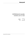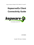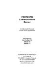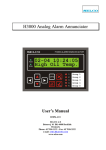
1
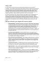
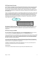
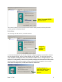
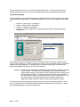
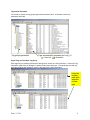
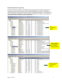
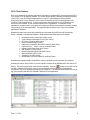
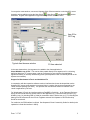
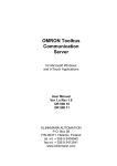
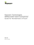
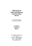
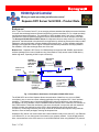
HC900 Hybrid Controller
When you need more than just discrete control
Kepware OPC Server for HC900 – Product Note
Background
OPC™ (OLE for Process Control™) is an emerging software standard that defines common interfaces
for easier data exchange between industrial equipment (such as controllers, PLC’s, or data recorders)
and Windows-based applications. The application of OPC standard “client” and “server” interfaces
eliminates the need for software packages to have a direct Modbus/TCP driver interface for HC900.
The Honeywell HC900 Ethernet OPC Server from Kepware utilizes a setup wizard for “automatic tag
generation” that allows data to be selected for an application by default tag names rather than modbus
addresses, reducing third party software database development time. In many software application
packages, the HC900 OPC Server tag list is browsed and selected parameters are simply added to
the database. OPC data exchange takes care of the rest!
Bottom Line - Kepware’s OPC Server for HC900 allows most popular HMI, SCADA, and historian
software packages plus custom interfaces using Visual Basic to easily access most HC900 data by
default tag name, expanding HC900’s open connectivity.
Kepware
OPC Server
with HC900
Ethernet
driver
OPC Client
interface
Defined by
OPC Standard
Modbus/TCP
protocol
Router
Ethernet
Client interface
To Wonderware
InTouch (via
FastDDE/
Suitelink interface
Ethernet
OPC Client
interface
Switch
Client interface
To Intellution
IFix (via
PDB interface
Fig. 1 Client-Server Architecture for Kepware HC900 OPC Server
The HC900 OPC server from Kepware allows communication of data from one or more HC900
controllers to one or more concurrent software applications having compliant OPC “client” interface
capability. The Kepware server (known as KEPServerEx) also provides direct, native interface to
Wonderware InTouch software via their FastDDE/Suitelink interface and to Intellution IFix software via
their PDB interface. These fast interfaces to the server, developed in conjunction with the respective
software vendors, are preferred over the OPC in these packages and provide similar client
connectivity. HC900 tags created by the setup wizard can be selected and imported using methods
familiar to users of these packages, lowering development time.
Kepware’s OPC Server can communicate with a client interface locally on the same PC, over Ethernet
on a different PC, or over the Internet via connection to a company network. On the HC900 network
side, communications to the OPC server is via an HC900 Ethernet driver using Modbus/TCP protocol.
Date: 3-17-03
1
History of OPC
In 1994, a group of vendors serving the industrial market formed what is known as the OPC
Foundation. The Foundation’s goal was to develop a single client/server specification that would allow
any vendor to develop software and applications that could share data in a fast, robust fashion that
eliminates proprietary schemes. Another Windows data transfer standard, DDE (Dynamic Data
exchange), did not provide the speed and robustness required for the industrial market. Their first
specification, called Data Access Specification 1.0a was released in 1996, now Data Access V2.0.
Using this specification, vendors are able to develop OPC server and client software.
On a more technical basis, OPC is based on Microsoft’s OLE (Object Linking and Embedding, now
ActiveX), COM (Component Object Model) and DCOM (Distributed Component Object Model)
technology and is available for all 32-bit Windows Operating Systems from Microsoft. COM and
DCOM enable the definition of standard objects, methods, and properties for servers of real-time data
from industrial control and data acquisition equipment. Additionally, OPC via an OPC Server, can
provide HMI or office applications with plant floor data via Ethernet networks, remote sites, or the
Internet.
What are the Benefits for the Kepware OPC Interface to HC900?
•
Open Connectivity – customers will be able to choose from a wider variety of client software
to communicate with HC900, allowing best-in-breed selection. The OPC standard has gained
increasing acceptance in recent years. There are hundreds of OPC servers available today
to communicate data from industrial hardware. Most popular HMI, SCADA and data
acquisition software offer OPC client functionality to allow this data to be easily imported as
tags within their database. This could be an HMI package such as GE Fanuc Cimplicity,
Rockwell RSView 32, or OSI Systems PI data historian software, for example. In addition, the
server also supports native, fast client interfaces to Wonderware InTouch and Intellution IFix
with similar ease of use.
•
Easy Setup using HC900 Wizard – allows HC900 OPC server to be created in a few
minutes for access to major control loop parameters, all set point programmer parameters,
Signal Tags, and Variables by default tag name. Signal Tags and Variables will also be listed
with analog and digital selections for interface as floating point or Boolean, depending on data
type configured in the HC Designer configuration.
•
Easy Connection to Client Applications - many software package clients offer a “browsing”
capability to view HC900 data groups generated by the wizard for selection and assignment
as tags. Applications written in various languages can communicate easily as long as they
are OPC compliant for the same version of OPC. The Kepware OPC server supports OPC
Versions 1.0 and 2.0.
•
Client/Server architecture – the HC900 OPC Server can communicate with several client
applications concurrently (such as data acquisition software and HMI packages). This can
occur locally on the same PC or remotely over Ethernet TCP/IP (via Microsoft’s DCOM).
•
High Performance – OPC provides high data throughput between the client interface and the
HC900 OPC server. Performance is preserved by an efficient implementation of the HC900
driver via the controller’s Mobus/TCP protocol.
•
Data Sharing Between OPC Servers – Kepware also includes their LinkMaster capability
on the product CD that allows it to access and link data from other OPC servers and offer that
data to any OPC/DDE client. The product provides the means of linking data between OPC
servers; thus, acting as a universal bridge for OPC server/client components.
Date: 3-17-03
2
OPC Data Access Overview
An OPC Server is comprised of several objects related to data access– the server, the group, and the
item. The OPC server object serves as a container for OPC group objects, which logically organize
OPC data items. Data items represent connections to data sources within the server. These data
sources consist of parameters within an HC900 controller. Data items related to the HC900, such as
those related to a control loop, are organized into named OPC data groups, automatically created by
the HC900 wizard.
There is no external interface defined for an individual OPC data item since all access is via OPC data
groups. Exception based connections can also be created between the client and the items in a group
and can be enabled and disabled as needed. The OPC client can configure the rate at which the
HC900 OPC server provides the data changes to the client (set typically to 500 ms). The group data
items may be either read or read/write dependent on the data type. Associated with each item is a
Value, Quality, and Time Stamp.
Group
“Loop_01”
Item 1 (HCChan.HC900a.Loop_01.PV)
Item 1 (HCChan.HC900a.Loop_01.WSP)
Item 1 (HCChan.HC900a.Loop_01.Output)
Data groups automatically created by the wizard may include different data types defined as floating
point, Boolean or Word (16-bit register). Data groups may also be created for other HC900
parameters not defined by the wizard. The data items in a group share the same update time and
deadbanding.
OPC Server Setup for HC900
On initial installation of the Kepware OPC Server, select the Honeywell Suite from the list of drivers.
This will install both the Honeywell HC900 Ethernet driver and Honeywell UDC driver.
To set up the OPC Server for the HC900 will require configuring the Channel and Device Type (HC900
Controller) for a project. Tag groups will be automatically generated per wizard entries but additional
tag groups can also be set up for tags not generated by the wizard. In this case, Modbus addresses
will need to be known for these parameters.
In most cases, the default selections for additional dialog boxes will be sufficient but it is suggested
that the Help button on the dialog boxes be utilized for further descriptions of these selections in case
another selection is more appropriate to the application.
In addition, for automatic startup, the OPC server should set up as a service under Windows NT or
2000 (typical environments for server and client applications).
Channel Setup
The first step is to add an Ethernet channel using the Honeywell HC900 Ethernet driver.
Date: 3-17-03
3
Select Honeywell HC900
Ethernet driver
The channel is named, driver plus NIC (Network Interface Card) selected, and write optimization
method (typically the default) selected.
Device Setup
The next step is to add a device, an HC900 controller.
Assign IP
address of
HC900
In consecutive dialog boxes, the controller is named, IP address assigned, communications timeouts
set (use defaults typically), and port number entered (use 502 default). The 32-bit data type word
order, as applied to floating point data, is next selected in the New Device – Settings dialog box. The
default is an un-checked box (this provides Honeywell controller standard format for 32-bit word order
selection - FP B, Big Endian). However, many software packages such as Wonderware and Intellution
have the reverse of this order as standard. In these cases, rather than changing it at the controller
level via the HC Designer tool, you may check the box as shown below.
For Wonderware or
Intellution floating point
data interface, check
this box
Date: 3-17-03
4
The next dialog box allows you to set the block transmission sizes. You may want to expand the
holding register block size to 64 or above if using SP programmers and accessing segment data.
Tag Generation Wizard
The final dialog box is for the HC900 automatic tag generation wizard. The device wizard for HC900
provides automatic tag generation, organized in tag groups, for the OPC server based on user entries
of:
Number of control loops in configuration
Number of Signal Tags in configuration
Number of Variables in configuration
Number of Setpoint Programmers in configuration plus number of segments for each
programmer
Consult the HC Designer configuration and enter the desired numbers for loops, Variables, Signal
Tags, and SP Programmers. If SP Programmers are entered, click on Details and enter the number of
segments for each programmer. Once these entries are made, the tag groups are automatically
generated with default tag names (you may alter as desired).
Important: The HC Designer configuration reports should be consulted as a reference for these
numeric entries. The control loop number sequence is per the Block Modbus
Address Report listing for loops while the Signal Tag and Variable numbering is per
the Tag Information Report. The Signal Tags and Variables are listed with both
float and Boolean selections to allow proper interface to the client application. The
user should refer to the Tag Information report to determine the data type
assignment (Digital translates to Boolean while Analog translates to Float).
The user may define other tag groups and provide tag entries based on Modbus addresses. In this
case, the HC900 Communications User Manual should be consulted (part # 51-52-25-111). Use the
wizard-generated tag list as a guide for data formats.
Date: 3-17-03
5
Tag Groups Generated
For the above entries, the tag groups generated are shown below. All relevant control loop
parameters are listed.
Tag groups generated
Tags automatically generated for Loop_01
= Read Only,
= Read/Write
Signal Tags and Variables Tag Groups
Each signal tag or variable is listed with 2 data types for access as a float or Boolean. Consult the Tag
Information report from HC Designer to determine the proper data type. The signal tags are read only
while the Variables are read/write, used for data entry from a client application.
Listed by
number,
each with
selection
of data
type
Date: 3-17-03
6
Setpoint Programmer Tag Groups
All communication parameters for the HC900 setpoint programmers are listed in sub-groups – a
Parameters group (for general status data and Start/Hold/Adv/Reset operation), an Additional
Parameters group (includes profile number access), and Segment data groups. These groups will
allow recipes to be generated in the client application and pointed to locations in the controller, or
simply allow selection of profiles stored in the controller.
SP
Programmer
Status
Profile #, profile
pool assignment,
Aux out status,
setup parameters
Setup parameters
for a selected
segment
Date: 3-17-03
7
OPC Client Interface
OPC Client interfaces for software applications can detect a compliant OPC server on the local PC or
on a remote PC on an Ethernet network. For remote network access, Microsoft’s DCOM functionality,
used in OPC, must be configured appropriately on your PC (see Kepware’s Remote DCOM
Connectivity guide on their website). Once a server is detected, the OPC Client application may
“Connect” to the selected server. In many user-friendly client applications, the tag groups for the
Server may be “browsed” by the client and clicked on for Tag selection. In other OPC Client
applications, the data items in a tag group are viewed as a reference and entered individually as tags
via text strings in the client application. The tags defined then become OPC Tags in the software
application’s database.
Kepware provides client connectivity examples in a document titled “KEPServerEx Connectivity
Guide”, available on the Kepware website. Client software interfaces documented include:
Automation Direct Lookout Direct (OPC Client)
Cutler-Hammer Panelmate PC Pro (OPC Client)
GE Fanuc Cimplicity (OPC Client)
Iconics Genesis32 (OPC Client)
Intellution FIX Dynamics and OPC Powertool (OPC Client)
Intellution IFIX ( Client – write-up available 2Q03)
Kepware OPC Quick Client (OPC Client)
OSI Systems PI (OPC Client)
Rockwell Software RSView32 (OPC Client)
Siemens WINCC (OPC client)
Think&Do Live (OPC Client)
Wonderware InTouch (FastDDE or SuiteLink Client)
Kepware also supplies sample Visual BASIC code for developing a low cost client user interface.
Kepware provides a “Quick Client” to provide real-time interface to the KEPServerEx OPC Server for
button on the OPC Server
testing. This client supports both read and write capability. When the
tool bar is selected and the OPC server found, the Kepware client application is automatically
connected to the server supporting all tag groups configured. The example below shows the Loop_01
tag group selected and Item ID’s updated in Kepware’s client application.
Date: 3-17-03
8
You may also create another, concurrent, Kepware Quick Client connection to simulate OPC server
browsing and tag additions using the New Server
, New Group
and New Item
selections. A typical client application might have a tag browser similar to below:
tool bar
Item ID for
OPC tag
Typical client browser window
PV Item selected
In the case shown above, the tag name to be added to the client application is
Chan1.HC900a.Loop_01.PV. This can be either pasted directly into a tagname cell in a client tag
definition dialog box or, in some cases, used as a reference for entry into the client application
tagname dictionary or similarly named dialog boxes (see Kepware’s Client Connectivity Guide on the
kepware.com website).
Support for Wonderware InTouch and Intellution IFix
In cooperation with the respective software vendors, interfaces have been developed that use the
Kepware OPC server setup structure but communicate in a native, fast structure supported by the
vendor software package (not OPC). This provides the most efficient means for interface to the
vendor’s application by the user.
For Wonderware InTouch, the interface would use FastDDE or SuiteLink. In the Tagname Dictionary
setup, the user would enter the access name for the application (e.g., KEPServerEX), the topic (e.g.
HC900a_Loop_01) including DDE or SuiteLink connection choice, and the item (e.g., PV) including the
data type as the reference for the InTouch TagName entered. See Kepware’s Client Connectivity
Guide for more detail.
For Intellution, the PDB interface is utilized. See Kepware’s Client Connectivity Guide for details (to be
updated to include this interface in 2Q03).
Date: 3-17-03
9
Kepware OPC Server Specifications
OPC Version Compliance: 1.0 and 2.0
System Requirements: Pentium 200MHz(400MHz rec.), 32MB RAM(64MB rec.), 10MB Disk space
Operating Environments: Windows *95, 98, NT (SP6a), 2000,XP (NT and 2000 strongly
recommended for industrial applications)
Update Rates: 500-1000 ms is typical selection for HC900 (500 ms analog scan rate)
Comm Support: Ethernet TCP/IP (HC900)
No. of Units: Only limited by network bandwidth using Ethernet
Data Access to HC900: via Modbus/TCP protocol
*Windows '95 requires Internet Explorer version 4.01 or higher along with a DCOM patch which can be
downloaded from Microsoft's web site.
Honeywell OPC Server Part Number: 51452976-001 (Honeywell OPC Server Suite from
Kepware, includes HC900 and UDC3300 drivers)
References
Websites:
http://opcfoundation.org (official OPC Foundation website)
http://kepware.com (for OPC overview, Client Connectivity Guide, Visual BASIC client
interface, remote DCOM connectivity)
http://content.honeywell.com/imc/pi/hybrid/hc900.stm (for general HC900 information and
manuals)
Manuals:
Honeywell HC900 Hybrid Controller Communications User Manual, # 51-52-25-111
Date: 3-17-03
10
Glossary
Name/Acronym
Active X
10Base-T
Name/Definition
A set of technologies developed by
Microsoft, largely based on OLE and
COM
Ethernet network using twisted pair
wiring and RJ-45 connectors, used in
star topologies
COM
Component Object Model
DCOM
Distributed Component Object Model
Ethernet
Hub
Internet
Modbus/TCP or
Modbus TCP/IP
LAN protocol defined by IEEE 802.3
networking standard (physical and
data link layers). Uses CSMA/CD
access method at a variety of speeds
and using several different media
A hardware device with multiple ports
enabling one device to be connected
to several others
A system of networks (local, regional,
national, and international) linked by
the TCP/IP protocol suite that
function as single, cooperative,
virtual network.
Variant of Modbus protocol
Date: 3-17-03
Most popular Ethernet standard. In the
name 10Base-T, the “10” refers to 10
Mbps transmission speed, the “Base”
refers to Baseband, which means that
no frequency multiplexing is applied,
and the “-T” refers Twisted Pair
conductors in the cable.
Component Object Model provides
interfaces and inter-component
communication. Through COM, an
application may use features of any
other application object. COM is the
core of DCOM, Active X, and OLE.
An extension of COM to support
objects distributed across a network
10 or 100 Mbps, Baseband network
that uses various media (twisted pair,
thick coax, thin coax, or fiber optic
cable).
Example: 10Base-T is 10 Mbps
Twisted Pair.
A hub forwards all messages on one of
its ports to all of its other ports with no
isolation between devices.
Modbus/TCP is a derivative of related
Modbus RTU protocol used with
RS232/RS-485 data acquisition and
supervisory structures. Basically,
Modbus/TCP encapsulates Modbus
RTU frames in TCP frames for
transport over an Ethernet network.
An object is some function that
produces a defined output, given that
the input meets predefined parameters
Object
OLE
Comments
Object Linking and Embedding
A technique that allows users to create
objects with one application and then
link or embed them in a second
application. Embedded objects retain
their original format but are linked to
the application that created them.
11
Protocol
Router
Switch
TCP/IP
Date: 3-17-03
A system of rules for communicating
over a network.
A device that is capable of filtering
messages based on IP addresses.
A multi-port Ethernet device that
switches traffic between two or more
network segments on an addressselective basis. Also called
switching hubs.
Transport Control Protocol/Internet
Protocol
An Ethernet switch looks like a hub,
but unlike a hub automatically
determines and remembers where an
Ethernet device is located and routes
messages only through the appropriate
port. This minimizes network loading
and enables true deterministic
communications over Ethernet by
eliminating “collisions”.
Transmission Control Protocol (TCP):
- Operates at the Transport Layer of
the OSI Model. - manages
connections between computers.
Internet Protocol (IP):
- operates at the Network Layer (one
step below TCP)
- defines how data is addressed
(source/destination)
12