1
User Manual
Copyright SpecView 1994 - 2007
3.04
For SpecView Version 2.5 Build #830/32
Disclaimer
SpecView software communicates with industrial instrumentation and displays and stores the
information it receives. It is always possible that the data being displayed, stored or adjusted is not as
expected. ERRORS IN THE DATABASE OR ELSEWHERE MEAN THAT YOU COULD BE READING
OR ADJUSTING SOMETHING OTHER THAN THAT WHICH YOU EXPECT!
Safety devices must ALWAYS be used so that safe operation of equipment is assured even if
incorrect data is read by or sent from SpecView.
SpecView itself MUST NOT BE USED IN ANY WAY AS A SAFETY DEVICE!
SpecView will not be responsible for any loss or damage
caused by incorrect use or operation, even if caused by
errors in programs supplied by SpecView Corporation.
Warranties & Trademarks
This document is for information only and is subject to change without prior notice.
SpecView is a registered trademark of SpecView Corporation
Windows is a trademark of Microsoft Corporation.
All other products and brand names are trademarks of their respective companies.
Copyright 1995-2007 by SpecView Corporation. All Rights Reserved.
This document was produced using HelpAndManual.
Contents
I
I
Table of Contents
Foreword
1 Installation
0
1
1.1 Instrument...................................................................................................................................
Installation and Wiring
1
1.2 Instrument...................................................................................................................................
Settings
2
1.3 RS422/EIA422
................................................................................................................................... 2
1.4 RS485/EIA485
................................................................................................................................... 2
1.5 Ethernet and
...................................................................................................................................
TCP/IP
3
1.6 Troubleshooting
...................................................................................................................................
Instrument Communication
3
1.7 Connections
...................................................................................................................................
for SpecView Networking
5
1.8 Installing SpecView
................................................................................................................................... 6
1.9 Upgrading...................................................................................................................................
SpecView from a previous version
9
2 Quick Start Guide
11
2.1 Quick Start
...................................................................................................................................
- Introduction
11
2.2 Quick Start
...................................................................................................................................
- Starting SpecView
12
2.3 Quick Start
...................................................................................................................................
- Manual Configuration
13
2.4 Quick Start
...................................................................................................................................
- For Instruments using the Modbus Protocol
16
2.5 Quick Start
...................................................................................................................................
- Automatically detect instruments and display instrument views
17
2.6 Quick Start
...................................................................................................................................
- Add a variable to the GDW
20
2.7 Quick Start
...................................................................................................................................
- Draw a trend chart
23
2.8 Quick Start
...................................................................................................................................
- Define a second GDW
25
2.9 Quick Start
...................................................................................................................................
- Add buttons to switch between GDW's
26
2.10 Quick Start
...................................................................................................................................
- Add a Bar chart
27
2.11 Quick Start
...................................................................................................................................
- See how it works in Runtime mode
28
3 SpecView Networking
30
3.1 Setting up
...................................................................................................................................
SpecView Networking
30
3.2 SpecView...................................................................................................................................
Networking - Local
31
3.3 SpecView...................................................................................................................................
Networking - Remote
32
3.4 SpecView...................................................................................................................................
Networking - Via Modems
36
3.5 SpecView...................................................................................................................................
Networking via Modem - Setup
37
3.6 SpecView...................................................................................................................................
Networking via Modem - Failure
38
3.7 SpecView...................................................................................................................................
Networking via Modem - Using HyperTerminal
39
Copyright SpecView 1994 - 2007
II
SpecView32 Main Help
II
3.8 SpecView...................................................................................................................................
Networking via Modem - Modem Types
41
3.9 SpecView...................................................................................................................................
Networking via Modem - TAPI Versions
42
3.10 SpecView...................................................................................................................................
Networking - Runtime Functions (on Remote)
42
3.11 SpecView...................................................................................................................................
Networking - Runtime Functions (on Local)
43
3.12 SpecView...................................................................................................................................
Networking - Troubleshooting
43
3.13 SpecView...................................................................................................................................
Networking - Minimum Requirements
44
4 Starting SpecView and Instrument
Definition/Detection
45
4.1 Starting SpecView
................................................................................................................................... 45
4.2 Archive and
...................................................................................................................................
Restore
47
4.3 Restore -...................................................................................................................................
Overwrite Configuration Warning
49
4.4 SpecView...................................................................................................................................
Command Line Options
49
4.5 Instrument
...................................................................................................................................
Definition/Detection
50
4.6 Manually...................................................................................................................................
Defining Instruments
50
4.7 For Instruments
...................................................................................................................................
using the Modbus Protocol
53
4.8 Automatic
...................................................................................................................................
Instrument Detection
54
4.9 TCP/IP Auto
...................................................................................................................................
Detection
56
4.10 Add/Rename
...................................................................................................................................
Instruments
58
4.11 Troubleshooting
...................................................................................................................................
Instrument Communication
59
4.12 Using a BarCode
...................................................................................................................................
Scanner with SpecView
61
4.13 HC900 HCDesigner
...................................................................................................................................
Modbus Map Import
63
67
5 Using SpecView
5.1 Runtime ...................................................................................................................................
Mode
67
5.2 Data Entry
................................................................................................................................... 68
5.3 Data Entry
...................................................................................................................................
- Numeric
69
5.4 Data Entry
...................................................................................................................................
- Boolean
70
5.5 Data Entry
...................................................................................................................................
- Enumeration
70
5.6 Data Entry
...................................................................................................................................
- Text Strings
71
5.7 Data Entry
...................................................................................................................................
- Date and Time
71
5.8 Parameter
...................................................................................................................................
List
73
5.9 Trend Charts
................................................................................................................................... 74
5.10 Trend Chart
...................................................................................................................................
Cursors
74
5.11 Runtime ...................................................................................................................................
Menubar
75
Runtime Menus
.........................................................................................................................................................
File Menu.........................................................................................................................................................
(Runtime)
Logging Menu
.........................................................................................................................................................
Copyright SpecView 1994 - 2007
75
76
78
Contents
III
III
History Menu
.........................................................................................................................................................
Recipe Menu
.........................................................................................................................................................
Alarms Menu
.........................................................................................................................................................
Password.........................................................................................................................................................
Menu (Runtime)
Remotes .........................................................................................................................................................
Menu
Options Menu
.........................................................................................................................................................
Zoom Menu
.........................................................................................................................................................
Window Menu
.........................................................................................................................................................
(Runtime)
Help Menu
.........................................................................................................................................................
(Runtime)
6 Configuring SpecView
78
78
78
79
79
80
81
82
82
83
6.1 Configuration
...................................................................................................................................
Menubar
83
Configuration
.........................................................................................................................................................
Menubar & Toolbar
File Menu.........................................................................................................................................................
(Configuration)
Edit Menu.........................................................................................................................................................
Draw menu
.........................................................................................................................................................
Object Menu
.........................................................................................................................................................
View Menu
.........................................................................................................................................................
Password.........................................................................................................................................................
Menu (Configuration)
Setup Menu
.........................................................................................................................................................
Window Menu
.........................................................................................................................................................
(Configuration)
Help Menu
.........................................................................................................................................................
(Configuration)
83
84
86
88
89
91
93
94
97
97
6.2 Configuring
...................................................................................................................................
GDWs - Graphical Display Windows
98
Configuring
.........................................................................................................................................................
SpecView
GDWs - Graphical
.........................................................................................................................................................
Display Windows
Extruder Graphic
.........................................................................................................................................................
Creating /.........................................................................................................................................................
Editing GDW's
Variables
.........................................................................................................................................................
List
SpecView
.........................................................................................................................................................
Variables
SpecView.FastCount
.........................................................................................................................................................
Variable
Adding Numeric
.........................................................................................................................................................
Values to a GDW
Variable .........................................................................................................................................................
Properties
Boolean.........................................................................................................................................................
Names
Alarms .........................................................................................................................................................
Dynamic.........................................................................................................................................................
Attributes Dialog Box
Color Dynamics
.........................................................................................................................................................
Insert New
.........................................................................................................................................................
Object
Edit Links
.........................................................................................................................................................
98
99
99
99
100
101
106
107
107
110
110
110
112
113
114
6.3 Drawing...................................................................................................................................
Basics
114
Drawing.........................................................................................................................................................
Menu and Toolbar
Selecting,
.........................................................................................................................................................
Grouping & Saving drawing objects
Shape Properties
.........................................................................................................................................................
Objects .........................................................................................................................................................
in front / behind others
Quick Copying
.........................................................................................................................................................
of Drawing Objects
Select Tool
.........................................................................................................................................................
Line Drawing
.........................................................................................................................................................
Tool
Rectangle
.........................................................................................................................................................
Drawing Tool
Round Rectangle
.........................................................................................................................................................
Drawing Tool
Ellipse Drawing
.........................................................................................................................................................
Tool
Copyright SpecView 1994 - 2007
114
115
116
116
117
117
117
118
118
118
IV
SpecView32 Main Help
IV
Polygon.........................................................................................................................................................
Drawing Tool
Bitmaps.........................................................................................................................................................
on a GDW
Bitmap Properties
.........................................................................................................................................................
Text on a.........................................................................................................................................................
GDW
Text Attributes
.........................................................................................................................................................
Trend Chart
.........................................................................................................................................................
Drawing Tool
Bar Chart
.........................................................................................................................................................
Drawing Tool
Buttons .........................................................................................................................................................
- Drawing on a GDW
118
119
119
119
120
121
121
122
6.4 Button Attributes
...................................................................................................................................
& Strategy Controller Actions
122
Available.........................................................................................................................................................
Attributes/Actions
Alarm On/Off
.........................................................................................................................................................
Alarms: .........................................................................................................................................................
Show Alarm List
Events: Show
.........................................................................................................................................................
Event List
GDW Control:
.........................................................................................................................................................
Close this and Swap To GDW
GDW Control:
.........................................................................................................................................................
Close this Screen
GDW Control:
.........................................................................................................................................................
Swap to another GDW
GDW Control:
.........................................................................................................................................................
Toggle Full Screen Mode
GDW Control:
.........................................................................................................................................................
Zoom in
GDW Control:
.........................................................................................................................................................
Zoom Out
GDW Control:
.........................................................................................................................................................
Print Screen
History: .........................................................................................................................................................
Start Replay
Logging:.........................................................................................................................................................
Convert Specific Log File Format
Logging:.........................................................................................................................................................
On/Off
Logging:.........................................................................................................................................................
Purge Log Files
Logging:.........................................................................................................................................................
Show File Convert Manager
Parameters:
.........................................................................................................................................................
Alter Value Interactively
Parameters:
.........................................................................................................................................................
Copy From.. To
Parameters:
.........................................................................................................................................................
Download Specific Value
Parameters:
.........................................................................................................................................................
Math Function
Parameters:
.........................................................................................................................................................
Show Full Parameter List
Password:
.........................................................................................................................................................
Log In or Log Out
Recipe: Download
.........................................................................................................................................................
Specific Recipe
Recipe: Show
.........................................................................................................................................................
Recipe Manager
Recipe: Show
.........................................................................................................................................................
Recipe Manager (Read Only Mode)
Recipe: Show
.........................................................................................................................................................
Recipe Manager (Read Only Send To Mode)
Recipe: Show
.........................................................................................................................................................
Recipe Manager (Send To Mode)
SpecView:
.........................................................................................................................................................
Exit Program
SpecView:
.........................................................................................................................................................
Maximize screen, Minimize Screen, Restore Screen
SpecView:
.........................................................................................................................................................
Run External Program
SpecView:
.........................................................................................................................................................
Write Line to file/printer
122
123
124
124
124
124
124
125
125
125
125
126
126
126
127
127
127
127
128
129
131
132
132
132
132
133
133
133
133
133
134
7 Full Screen Mode
136
8 Trend Charts
136
9 Bar Charts
139
10 Recipes
141
Copyright SpecView 1994 - 2007
Contents
V
V
10.1 Recipes...................................................................................................................................
- Overview
141
10.2 Selecting
...................................................................................................................................
Variables to be Included in Recipe
142
10.3 Recipes...................................................................................................................................
- Using
143
10.4 Recipe Warning
................................................................................................................................... 144
10.5 Recipe Names
................................................................................................................................... 145
10.6 Recipe Description
................................................................................................................................... 145
10.7 Recipe Hide
...................................................................................................................................
this box
146
10.8 Recipe Save
...................................................................................................................................
& Save As
146
10.9 Recipe Import/Export
................................................................................................................................... 146
10.10 Recipe Send
................................................................................................................................... 147
10.11 Recipe "Send
...................................................................................................................................
To"
148
10.12 Source ...................................................................................................................................
and Target Instruments
148
10.13 Recipe Send
...................................................................................................................................
To: Warning
149
10.14 Recipe "Send
...................................................................................................................................
To" Problems
149
10.15 Setting ...................................................................................................................................
the recipe download order
149
10.16 Recipe on
...................................................................................................................................
Remote
150
11 Preferences
151
11.1 Preferences
...................................................................................................................................
Dialog Box
151
11.2 Preferences
...................................................................................................................................
- Runtime
151
11.3 Preferences
...................................................................................................................................
- Remote
152
11.4 Preferences
...................................................................................................................................
- Display
153
11.5 Preferences
...................................................................................................................................
- Alarm
154
11.6 Preferences
...................................................................................................................................
- Logging
154
11.7 Preferences
...................................................................................................................................
- Strategy
154
11.8 Preferences
...................................................................................................................................
- Recipe
155
11.9 Preferences
...................................................................................................................................
- Startup
155
11.10 Preferences
...................................................................................................................................
- History
155
11.11 Preferences
...................................................................................................................................
- Settings
156
11.12 Preferences
...................................................................................................................................
- Web Server
156
11.13 Preferences
...................................................................................................................................
- Logfile Conversion
157
11.14 Preferences
...................................................................................................................................
- DDE
157
11.15 Preferences
...................................................................................................................................
- Debug
157
12 Passwords
158
12.1 Passwords
...................................................................................................................................
- Overview
158
12.2 Passwords
...................................................................................................................................
- GDW Setup
159
Copyright SpecView 1994 - 2007
VI
SpecView32 Main Help
VI
12.3 Passwords
...................................................................................................................................
- Selecting Objects for Access
161
12.4 Passwords
...................................................................................................................................
- User Control
161
13 Data Logging
162
13.1 Data Logging
...................................................................................................................................
- Overview
162
13.2 Data Logging
...................................................................................................................................
- Variables
163
13.3 Data Logging
...................................................................................................................................
- Disk Space Requirements
164
13.4 Data Logging
...................................................................................................................................
- Rate
165
13.5 Log Reports
................................................................................................................................... 166
13.6 Log Report
...................................................................................................................................
Setup
167
13.7 Log Reports
...................................................................................................................................
from the Remote
168
13.8 Log Report
...................................................................................................................................
Format
168
13.9 Log Reports
...................................................................................................................................
- Specifying decimal places
171
13.10 Data Logging
...................................................................................................................................
- Alarms
172
13.11 Data Logging
...................................................................................................................................
- Events
173
13.12 Historical
...................................................................................................................................
Replay Option
174
13.13 Historical
...................................................................................................................................
Replay - Control Panel
174
13.14 Historical
...................................................................................................................................
Replay - Start Time
175
13.15 Historical
...................................................................................................................................
Replay - Find Batch Number
175
13.16 Historical
...................................................................................................................................
Replay - Rate
176
13.17 Historical
...................................................................................................................................
Replay - Options
176
13.18 Batch Tags
................................................................................................................................... 176
14 Strategy Controller
179
14.1 Strategy...................................................................................................................................
Controller - Overview
179
14.2 Programming
...................................................................................................................................
the Strategy Controller
180
14.3 Example:
...................................................................................................................................
Automatic Log Report
181
14.4 Event Type
................................................................................................................................... 191
14.5 Value (Variable)
...................................................................................................................................
Based Event Setup
191
14.6 Time Based
...................................................................................................................................
Event Setup
193
14.7 Strategy...................................................................................................................................
Controller Actions
194
14.8 Examples
...................................................................................................................................
of Value Based Events
195
14.9 Turn on...................................................................................................................................
a digital output on a New Alarm
195
14.10 Count Up
...................................................................................................................................
Timer
196
14.11 Cascade...................................................................................................................................
Control
198
14.12 Totalizer................................................................................................................................... 200
14.13 Examples
...................................................................................................................................
of Time Based Events
201
Copyright SpecView 1994 - 2007
Contents
VII
15 ActiveX Controls
VII
202
15.1 ActiveX...................................................................................................................................
Overview
202
15.2 ActiveX...................................................................................................................................
Method of Adding an ActiveX Control
202
15.3 ActiveX...................................................................................................................................
Licensing
205
15.4 ActiveX...................................................................................................................................
On SpecView Remote
206
15.5 ActiveX...................................................................................................................................
Insert Control
206
15.6 ActiveX...................................................................................................................................
Preferences
207
15.7 ActiveX...................................................................................................................................
Variables Inputs
208
15.8 ActiveX...................................................................................................................................
Variables Outputs
209
15.9 ActiveX...................................................................................................................................
Variables Methods
211
15.10 ActiveX...................................................................................................................................
Register
212
15.11 ActiveX...................................................................................................................................
Manage Control List
213
15.12 ActiveX...................................................................................................................................
Control Not Licensed
214
16 DDE
214
16.1 DDE (Dynamic
...................................................................................................................................
Data Exchange) - Overview
214
16.2 DDE Application
...................................................................................................................................
Name
215
16.3 DDE Topic
...................................................................................................................................
Name
215
16.4 DDE Status
...................................................................................................................................
Topic
215
16.5 SpecView
...................................................................................................................................
DDE Restrictions
215
16.6 Getting ...................................................................................................................................
data from SpecView DDE
216
16.7 Setting data
...................................................................................................................................
into SpecView DDE
216
16.8 DDEPoke
...................................................................................................................................
Examples
217
16.9 Setting up
...................................................................................................................................
an Excel DDE Poke Example
217
16.10 DDE Read
...................................................................................................................................
Example
218
17 SpecView Error Codes
219
17.1 SpecView
...................................................................................................................................
Error Types
219
17.2 SpecView
...................................................................................................................................
Write Errors
219
17.3 SpecView
...................................................................................................................................
Generic Error Codes
220
17.4 Error Codes
...................................................................................................................................
- Protocol Specific
221
18 Upgrading SpecView
222
19 OPC Client Support in SpecView
225
19.1 OPC Client
...................................................................................................................................
Support - Overview
225
19.2 OPC Browser
................................................................................................................................... 227
Copyright SpecView 1994 - 2007
VIII
SpecView32 Main Help
VIII
19.3 Supported
...................................................................................................................................
OPC Servers
229
19.4 OPC - Fequently
...................................................................................................................................
Asked Questions (FAQs)
231
19.5 OPC - PC
...................................................................................................................................
Specification/Performance
232
20 Technical Support
234
20.1 Contact...................................................................................................................................
Information
234
20.2 USA Contact
...................................................................................................................................
Numbers
234
20.3 UK Contact
...................................................................................................................................
Numbers
234
20.4 Europe ...................................................................................................................................
Contact Numbers
235
20.5 Internet...................................................................................................................................
Support
235
21 Licensing in SpecView
235
22 Minimum Requirements for
running SpecView
236
23 Frequently Asked Questions (FAQ)
237
23.1 FAQ - Index
................................................................................................................................... 237
23.2 FAQ - Installation/Upgrade
................................................................................................................................... 238
23.3 FAQ - Instrument
................................................................................................................................... 239
23.4 FAQ - SpecView
...................................................................................................................................
Runtime
239
23.5 FAQ - SpecView
...................................................................................................................................
Configuration
243
24 Glossary of Key Terms used in
SpecView
249
24.1 Glossary
...................................................................................................................................
Index
249
24.2 Alarms ................................................................................................................................... 250
24.3 Boolean................................................................................................................................... 250
24.4 COM Port
...................................................................................................................................
Settings
250
24.5 Communications
...................................................................................................................................
Ports "Com Port"
251
24.6 Communications
...................................................................................................................................
Protocol
251
24.7 Configuration
................................................................................................................................... 252
24.8 Configuration
...................................................................................................................................
Mode
252
24.9 Data Logging
................................................................................................................................... 252
24.10 Decimal...................................................................................................................................
Places
253
24.11 Dongle ................................................................................................................................... 253
24.12 Dynamic...................................................................................................................................
Attributes
254
24.13 GDO - Graphical
...................................................................................................................................
Display Object
254
Copyright SpecView 1994 - 2007
Contents
IX
IX
24.14 GDW - Graphical
...................................................................................................................................
Display Window
254
24.15 Instrument
................................................................................................................................... 254
24.16 Instrument
...................................................................................................................................
View
254
24.17 Log Report
................................................................................................................................... 255
24.18 Multiport
...................................................................................................................................
Option
255
24.19 Radio Buttons
................................................................................................................................... 256
24.20 Read Only
...................................................................................................................................
Variable
256
24.21 Recipe ................................................................................................................................... 256
24.22 Runtime...................................................................................................................................
Mode
256
24.23 Strategy...................................................................................................................................
Controller
257
24.24 Toggle ................................................................................................................................... 257
24.25 Tooltips................................................................................................................................... 257
24.26 Variable................................................................................................................................... 258
24.27 Variable...................................................................................................................................
Types
258
24.28 Variables
...................................................................................................................................
List
258
24.29 Web Server
...................................................................................................................................
Option
258
24.30 Windows
...................................................................................................................................
filenaming rules
259
24.31 Writeable
...................................................................................................................................
Variable
259
Index
Copyright SpecView 1994 - 2007
260
1
SpecView User Manual
1
Installation
1.1
Instrument Installation and Wiring
Instrument Installation and Wiring
NOTE: If you cannot establish communications between SpecView and your instruments first
check your instrument's manual for correct wiring instructions. For further assistance please
contact the instrument manufacturer. Many have test programs that will check your converter
and connections.
RS232
Most computers have built in standard RS232 (9-pin) ports specified as:
Pins
Code
Description
Input/Output
1
DCD
Data carrier detect
Input
2
RXD
Receive data
Input
3
TXD
Transmit data
Output
4
DTR
Data terminal ready
Output
5
GRND
Ground
N/A
6
DSR
Data set ready
Input
7
RTS
Request to send
Output
8
CTS
Clear to send
Input
9
RI
Ring indicator
Input
If the intention is to use RS232 wiring to connect the instrument, then the wiring and the connection to the instrument
will be specified by the instrument's manufacturer.
RS232 is point-to-point, therefore it has a maximum of a single instrument connection.
RS422 & RS485
If the intention is to use RS422 or RS485 wiring to connect the instrument, then an external converter from RS232 to
either RS422 or RS485 (as appropriate) must be used. SpecView recommends (and can supply) converters made by
B&B Electronics.
The reason the B&B device is recommended is because it has "Automatic Send Data Control", this automatically
switches from transmit to receive and so works very well with SpecView.
Please note that RS422/485 connections should be terminated correctly, please see the instrument manufacturer's
instructions.
NOTE: We strongly caution against using internal 422/485 cards
Unless you are expert in testing and troubleshooting communications we recommend using internal RS232 ports and
external isolated converters. Since all computers have 232 ports a second computer can be used to determine
whether a problem is in the computer or wiring if an external converter has been used.
· Each serial port MUST operate with its own interrupt unless special interrupt sharing cards and software are
used.
·
Serial ports using 16550 UARTS or above are strongly recommended, especially if BAUD rates above 9600 are
going to be used. They are required for instruments that use block mode data reading.
Copyright SpecView 1994 - 2007
Installation
2
The number of controllers that can be connected to SpecView is only limited by the available addresses on the
controllers. Most instruments go to 99 addresses and SpecView supports up to 40 ports.
RS422 and RS485 would need repeaters if there are more than 16 or 32 instruments respectively. Please see the
instrument manufacturer's instructions or the converter's manual.
Instrument Settings
RS422 (EIA422-A) Instruments
RS485 (EIA485) Instruments
Ethernet and TCP/IP
Troubleshooting Instrument Communication
Connections for SpecView Networking
1.2
Instrument Settings
Instrument Settings
SpecView has help available for several makes of instruments:
The Ports and Protocols box (which is accessed by clicking the Test Comms for new Config button on the
"Configurations Found" dialog box). is used for automatic detection of connected instruments.
On this box when a protocol is chosen, for a given port a Help button appears for that port. Each port can use a
different protocol if required.
Clicking the Help button will open a separate help file specifically for that protocol. Refer to it for details on setting your
instruments.
You can also get this help by double-clicking on the instrument name in the Variables List accessed by clicking the
tool
1.3
RS422/EIA422
RS422/EIA422
RS422 this is a 4 wire connection and has a maximum cable length of 1.2 km and a maximum of 10 instrument
connections.
All four wires MUST be used. Follow the instrument manufacturers instructions carefully, paying attention to shielding
in electrically noisy environments.
The converter will have two Transmit (sometimes called Send) and two Receive connections
These are marked either "+" & "-" or "A" & "B" (or both)
· In general, the Transmit connections on the converter go to the Receive connections on the instrument.
·
In general, the Receive connections on the converter go to the Transmit connections on the instrument.
· In general, the "+" or "B" connections on the converter go to the "+" or "B" connections on the instrument.
NOTE: Most instruments made by Eurotherm Controls DO NOT follow this convention. In most cases connect
Converter T+ (or B) to Instrument R-, Converter T- (or A) to Instrument R+ and so on. Please check this in
Eurotherm's Instrument Manual.
1.4
RS485/EIA485
RS485/EIA485
RS485 this is a 2 wire connection and has a maximum cable length of 1.2 km and a maximum of 32 instrument
connections.
Although this is normally a two wire connection some instruments use four wires.
Follow the instrument manufacturers instructions carefully, paying attention to shielding in electrically noisy
Copyright SpecView 1994 - 2007
3
SpecView User Manual
environments.
Two wire converters will have connections marked "A" or "-" and "B" or "+". These go to the corresponding
connections on the instrument.
If the instrument has four connections you should use a converter with four connections.
If you are told by your instrument manufacturer that you can use a two wire converter, on the controller jumper the
Transmit + (or B) to the Receive + (or B) and the Transmit - (or A) to the Receive - (or A). This leaves you with one "+"
(or B) connection and one "-" (or A) connection to make to the converter.
Four wire converters will have two Transmit (sometimes "send") and two Receive connections.
If your instrument has four connections read the RS422/EIA422 help
These marked either "+" & "-" or "A" & "B" (or both)
If your instrument has two connections, on the converter jumper the Transmit + (or B) to the Receive + (or B) and
the Transmit - (or A) to the Receive - (or A). This leaves you with one "+" (or B) connection and one "-" (or A)
connection.
1.5
Ethernet and TCP/IP
Ethernet and TCP/IP
SpecView also supports communications via modbus/TCP through Window's TCP/IP networking, or by external TCP
converter modules.
Further information on addressing is detailed in Modbus addressing
1.6
Troubleshooting Instrument Communication
Troubleshooting Instrument Communication
What to do if your instrument is just displaying "XXX" instead of the correct values when in Runtime mode:
Is this a new installation of SpecView, which has not as yet ever worked?
Is this happening for ALL of the instrument's variables?
If the answers to the above 2 questions is Yes, then:
o Has the wiring between the instrument & the PC been checked?
o Has the instrument's manufacturer's manual been checked for any relevant information? For example, the
setting of the instrument's address (address 0 should not be used).
o Is the instrument's address, baud-rate and parity correctly set on the instrument?
o Is the instrument's address is correctly specified in SpecView? (Click the Variables List tool, select the
instrument's name and click Properties, then click Address Help)
o Check the instrument is connected to the correct COM port, as specified in SpecView.
o Does the COM port on the computer work? (Use HyperTerminal to test the COM port). And is the correct type
of COM card fitted in the instrument?
o Is the instrument's baud-rate and parity correctly specified in SpecView? From Runtime mode use the 'Setup
COM Ports' menu command on the Options menu, click the tab for the appropriate COM port. Check the
baud-rate & note down the name & version number of the driver. When the Settings are show "Default" that
means that the data-bits, parity & stop-bits have been set according to the factory defaults as specified in the
instrument manufacturer's manual.
o Is the instrument using the correct protocol? (for example, ASCII protocol versus modbus protocol)
o Is the instrument terminated correctly?
o Do you need a converter, which is needed for: RS422 or RS485 serial comms? (The reason the B&B
converter is recommended for SpecView is because it has "Automatic Send Data Control", which
automatically switches from transmit to receive).
o Does the converter work? Has it been wired up correctly according to the wiring diagram supplied with it?
Does it require power and is it switched on? Have any dip-switches been set according to the instructions? Do
other connected instruments work? Is it possible to swap it around to test it?
o Has SpecView's Online Technical Notes been checked for this instrument type? Access www.specview.com
then click Download and click FTP-site and open the TechNotes folder.
o Some instruments have to be setup to allow their variables to be read. For example, setting the access level.
o If the XXX is coming from an OPC Server, then contact your OPC Server's administrator to see if the OPC
Server is running correctly.
o If all of this has been checked then please contact your instrument's supplier.
Copyright SpecView 1994 - 2007
Installation
4
If SpecView has been working successfully, but has now stopped working, or if just some of the instrument's
variables are displaying as "XXX", then:
o Firstly be aware that some instruments are designed in such a way that, depending on the instrument setup,
instrument mode or program considerations, some values are legitimately unavailable - these variables will be
shown as XXX's. This is normal & correct behaviour for that instrument. Two common examples of this are: 1:
Programmer instruments, where segment variables change their availability depending on segment type. 2:
Instruments where optional hardware is not present, for example output boards not fitted, or auxilliary inputs
not configured/fitted. Please see the instrument manual for which variables may or may not be available under
these circumstances.
o Is this an intermittent failure?
o What is the value of the variables: SpecView.BadComms, SpecView.GoodComms,
SpecView.CommsErrorCode & SpecView.CommsErrorItem? These variables can be added to a GDW
and/or logged. To Log these variables, use "Database->Show Logging in Variables List" from the Setup menu
and check the boxes next to these variables in the Variables List, then from Runtime mode use Convert Log
File from the Logging menu to create a Log File Convert Format which contains these variables. Note that the
variables will not be listed in the Log Format Setup box until they have been logged according to the rate
defined in Preferences - Logging or from the action Logging: On/Off.
o Has the wiring between the instrument & the PC been checked and tested?
o Has anything been altered or added to either hardware or software?
o Has SpecView's Address Help for the instrument been checked? To view this go into Configuration mode, use
the Variables List tool, select the instrument's name and click the Properties button, then click Address Help.
o Has SpecView's Online Technical Notes been checked for this instrument type? Access www.specview.com
then click Download and click FTP-site and open the TechNotes folder.
Using the Line Writer to troubleshoot comms problems:
This will create a file which lists the date, time & cause of any comms errors.
(This will be a file separate to SpecView's standard Log Files or Log File Reports).
To do this create a Strategy Controller value based event: "When BadComms changes" that watches
SpecView.BadComms and when it changes does the action SpecView: Write Line to file/printer of:
+CommsErrors.csv
%%SpecView.Date%%,%%SpecView.Time%%,%%SpecView.GoodComms%%,%%SpecView.BadComms%%,%%S
pecView.CommsErrorCode%%,%%SpecView.CommsErrorItem%%
It is also a good idea to remove the commas from the date format in Preferences - Display to prevent these commas
from adding unnecessary columns to the CSV file.
Using SpecView's Driver Debug:
If all the above has been thoroughly checked then the next step is to send your SpecView representative Debug files.
These debug file(s) need to be as small as possible, at the same time as being as relevant as possible. The extra
effort taken to create these will be much appreciated by your SpecView representative and will enable them to give you
an answer promptly.
Therefore the aim is to have a minimal configuration (by using the New Manual Configuration button) with just a
single GDW displaying just one of the instrument variables which is causing trouble.
Alternatively, create a new GDW in an existing configuration, and put just one of the variables which is causing trouble
out on to it. Then using File->Preferences disable Logging (on the Logging tab), disable Alarms (on the Alarms tab)
and Strategy (on the Strategy tab). Ensure that none of your other GDWs have File->Auto-open on Runtime enabled.
(NB: Once the problem has been resolved these changes will need to be reversed).
To create the Debug file(s) follow the steps below:
If your instrument is NOT using the Modbus (or Modbus TCP/IP) protocol then use:
DEBUG = 1
Note: Not all drivers support DEBUG = 1, in which case you will see the error: "Driver commands not accepted" if this
occurs please contact your SpecView representative.
If your instrument is using the Modbus (or Modbus TCP/IP) protocol then use:
DEBUG = 15
DEBUGSIZE = 1
DEBUGAUTODEL = 9 (This will create up to nine 1Mb files)
To set these up:
From SpecView's Runtime mode use the Setup COM Port menu command from the Options menu, click the
Copyright SpecView 1994 - 2007
5
SpecView User Manual
appropriate tab for the port being used.
In the bottom-left-hand box enter DEBUG, then in the next box enter either 1 or 15 appropriately, then click the Add
button:
The Driver Commands box will now show the value for DEBUG.
Then (if required) do the same for: DEBUGSIZE = 1 and DEBUGAUTODEL = 9
Then wait for at least one minute, but no more than three minutes, then Exit SpecView
In your configuration folder under SpecView's installation folder (usually C:\SV32) you should now find some .TXT files
where the names start with "debug", for example: debug_COM1.txt
Email these file(s) to your SpecView representative.
You will also need to email an SVA (SpecView Archive) of your configuration. To do this use SpecView's Archive
button (which is on the Configurations Found dialog box when SpecView starts up). Ideally this should be done with
the "Include log files" checkbox un-checked.
Remember to set Debug back to zero afterwards.
1.7
Connections for SpecView Networking
Connections for SpecView Networking
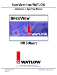
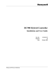
For SpecView Networking the connection can be made in 4 possible ways:
1. Via TCP/IP over a LAN (Local Area Network).
2. Via TCP/IP over a WAN (Wide Area Network) using an "always connected" phone line or Broadband
connection.
3. By making the Local computer available to the Internet so that the Remote computer(s) can access it over
their Internet link. However, this has security implications so is not recommended.
4. By using modems for SpecView to make a direct-dial connection between the computers when needed.
The diagrams below show example configurations:
Copyright SpecView 1994 - 2007
Installation
6
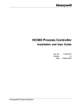
It is possible for a PC to run one SpecView Local and several copies of SpecView Remote simultaneously:
Setting up SpecView Networking
1.8
Installing SpecView
Installing SpecView
If there are any doubts about the suitability of the computer for installation of SpecView, or if you are using Windows
XP, please check the Minimum Requirements for Installing SpecView.
To install SpecView choose one of the following methods:
CD
If you have SpecView on a CD then load the CD into the drive. It should then automatically run Setup from the CD.
If the CD does not auto-run then double-click the
double-click the
icon.
Copyright SpecView 1994 - 2007
icon on your screen, open the Compact Disc and
7
SpecView User Manual
NOTE: It is strongly recommended to install into the default location C:\SV32
Demo Configurations
There are a number of fully functional example configurations pre-prepared for many of the instruments that we
support. These configurations can be easily installed, and may be modified to meet your exact requirements.
When installing from a CD, by default all the Demo Configurations are installed. Run SpecView then at the first screen
(Configurations Found), select the one that you require. Each Configuration is stored in its own sub-folder within the
installation folder (which is by default C:\SV32). The sub-folder can be copied using Windows Explorer, therefore it is
easy to make a backup of a configuration by making a copy of it, or by using SpecView's Archive/Restore facility.
These configurations can, if required, be modified from Configuration Mode.
The Demo Configurations are not included in the downloaded product, so they must be downloaded separately from
the website by selecting the most appropriate of these for your instrument(s). The file(s) you download is a .SVA file,
which is a SpecView Archive. To use one of these downloaded .SVA files, install and run SpecView, then at the
Configurations Found screen, press the Restore button. Find the .SVA file you have downloaded and restore the
configuration into SpecView. Once restored, these configurations can, if required, be modified from Configuration
Mode. However modifications will only affect the restored Configuration folder, not the downloaded .SVA file, therefore
the .SVA file can be considered as a backup which can be restored again if necessary.
Diskettes
If you have SpecView on diskettes, insert Disk 1 into drive A: double-click the
the 3½-Inch Floppy Disk and double-click the
icon on your screen, open
icon.
NOTE: It is strongly recommended to install into the default location C:\SV32
Download
Copyright SpecView 1994 - 2007
Installation
8
Downloading SpecView from http://www.specview.com can be done either by downloading the single file or the
multiple file version.
All files on the website have been zipped, therefore you will need to unzip them using, for example, WinZip (which can
be obtained from http://www.winzip.com) or another utility such as pkunzip.
Download the multiple file version if the computer(s) you intend to install it on is not the same as the computer which is
connected to the internet, and the only way to transfer files between the computers is by using floppy disks.
The multiple file version can be also used if there is a likelihood that the internet connection could be lost during the
download. If this is the case unzip all files into a single temporary folder on your hard disk and run SETUP.EXE,
Single file download:
Download the single file, unzip (using for example, WinZip) it into a temporary folder and then run SETUP. (Newer
versions of WinZip may run SETUP.EXE automatically for you).
For example, for SpecView version 748 the file is:
sv748_all.zip (13.5Mb)
Multiple file download - for floppy disks:
Download all the individual files into a temporary folder on your hard disk. For example, for SpecView version 748 the
files are:
sv748_1.zip
sv748_2.zip
sv748_3.zip
sv748_4.zip
sv748_5.zip
sv748_6.zip
sv748_7.zip
sv748_8.zip
sv748_9.zip
sv748_10.zip
Once they have been downloaded, extract each of them DIRECTLY onto individual separate (totally empty) floppy
disks.
NOTE: Do not COPY the ZIP files onto the floppies as they will not fit, they MUST be EXTRACTED
to the floppies.
The example below is for WinZip, which is not included with SpecView, but it can be obtained from
http://www.winzip.com
To extract them use Windows Explorer to list the downloaded files, and for each of them in turn, right-click and select
the Extract to... menu command which will run WinZip.
Copyright SpecView 1994 - 2007
9
SpecView User Manual
Select the Floppy (A:) and click Extract.
The numbered ZIP files contain numbered CAB files and these numbers will not necessarily match, i.e. the file:
SV748_6.ZIP may contain: Data7.cab
NOTE: Several of the floppy disk ZIP files contain files that will exactly fill a blank floppy.
If there is not enough space on the floppy to copy the files over, then use a new blank floppy.
Each of the files (when unzipped) will fit exactly onto its own floppy disk.
Newer versions of WinZip can be configured to run SETUP.EXE automatically, so when you unzip the first file, WinZip
tries to run SETUP before the other files are unzipped. If this happens, unzip the files in reverse order, or download the
single file.
Once all the floppy disks have been created, put floppy #1 into the drive of the computer which you intend to install it
on and run SETUP.EXE.
An alternative method is to Unzip all the files into a single temporary folder on your hard disk and then run
SETUP.EXE.
If you have difficulty during installation please contact your SpecView distributor.
Quick Start
Starting SpecView
1.9
Upgrading SpecView from a previous version
Upgrading SpecView from a previous version
Upgrading SpecView from an earlier version of SpecView 32 to a more recent version is just a matter of checking the
Upgrade/Repair check box in the InstallShield Wizard.
Copyright SpecView 1994 - 2007
Installation
10
However, upgrading to SpecView 32 from the older 16-bit version (called: SpecView Plus) is complicated by the fact
that the default installation folder changed from C:\SPECVIEW in the 16-bit version to C:\SV32 in the 32-bit version.
Upgrading from the 16-bit version is still possible without the need to re-create existing configurations by just copying
the configuration's sub-folder (from C:\SPECVIEW) over to the new installation (in C:\SV32).
Although it may be that different folder names were used during installation. If so then use the replacement folder
names accordingly.
Below is an example of copying a configuration folder (called: MM8TC) using Copy and Paste.
First navigate to the old C:\SPECVIEW folder. Find the MM8TC folder in the list of icons and right-click the folder. A
popup menu will appear.
Choose Copy from the menu. Navigate to the C:\SV32 folder. Find a blank space in the folder that does not have any
icons in it and right-click again. This will display the popup menu as follows - choose Paste.
(Note that it is important to click on a blank part of the window because clicking on an icon will result in the folder being
pasted into that folder, which will not result in a useable configuration.)
Copyright SpecView 1994 - 2007
11
SpecView User Manual
Once this is complete, run SpecView 32 and the configuration will be listed in the "Configurations Found" dialog box.
A configuration cannot however be copied from the 32-bit version back into the 16-bit version as there are some
incompatibilities between the two versions.
2
Quick Start Guide
2.1
Quick Start - Introduction
Quick Start - Introduction
NOTE: Press the F1 key at any time for help
This quick start guide covers the installation and initial configuration of SpecView.
When the computer is connected to an instrument via a serial port or Ethernet, SpecView gets data from and can send
data to the instrument. Unlike conventional SCADA software, where each data point has to be defined by the user,
SpecView has a pre-built database of hundreds of instruments. Most instruments, if already connected to the
computer, can be automatically detected by SpecView. If the instrument is not connected to the computer or if that
instrument does not support the auto-detection feature, the user picks it from a list. In SpecView this is called
"Manually Defining Instruments".
Once all the steps below have been followed, your screen should look similar to this:
(The "Instrument View" (the MM8TC-1 box on the left) will depend on the specific instrument being used)
Copyright SpecView 1994 - 2007
Quick Start Guide
12
The steps are as follows:
1. Installing SpecView
2. Starting SpecView
If you have no instrument currently connected to your computer then follow:
3. Manual Configuration
or, if you do have an Instrument(s) connected, then follow:
3. Automatically detecting instruments and displaying Instrument Views
then continuing:
4. Add a variable to the GDW (Graphical Display Window)
5. Draw a Trend Chart
6. Define a second GDW
7. Adding buttons to switch between GDW's
8. Adding a Bar chart to a GDW
9. Seeing how it works in Runtime Mode
To go to the next step click the link: Starting SpecView
NOTE: SpecView's name for each screen is a GDW (Graphical Display Window). Each GDW is saved as a file on
disk, much like a Word document.
2.2
Quick Start - Starting SpecView
Quick Start - Starting SpecView
Once SpecView is installed, double-click the SpecView icon, or click Start and select SpecView 32 from the Programs
menu.
If SpecView is started without a dongle connected then initially the following dialog box is displayed first. Click the
Start in DEMO Mode button to run in Demo mode.
Copyright SpecView 1994 - 2007
13
SpecView User Manual
This will display the Configurations Found
dialog box:
If a dongle is connected, the Configurations Found dialog box will be displayed directly.
If you have an instrument connected then go to Automatically detect instruments below.
Alternatively, if you have no instrument connected you can still configure SpecView by clicking the New Manual
Configuration button and then going to Manual Configuration
2.3
Quick Start - Manual Configuration
Quick Start - Manual Configuration
If you have no instrument connected clicking on New Manual Configuration will display the Input Required dialog box
Enter a name for the configuration. SpecView will create a sub-folder with this name in the SpecView folder (which is
normally C:\SV32), the name you enter should follow the Windows file naming rules and should not be too long.
Remember this name. This folder will be where all your log files and configuration files will be stored. Log Reports will
also be stored here unless another folder is specified.
When you have entered a name for the configuration and clicked OK this will immediately bring you into Configuration
Mode displaying a blank Graphical Display Window (GDW) grid.
Click the Variables List tool
on the Toolbar to display this dialog box. At this stage the only item
Copyright SpecView 1994 - 2007
Quick Start Guide
14
listed will be SpecView.
NOTE: When using the Toolbar, move the pointer over a tool and the Tool Tip will tell you what it
does.
Click the Show New button, which will list the pre-defined instrument types:
Scroll down the list of available instruments to find the name of the instrument you intend to connect. Click the
symbol beside the instrument you require to display the specific instrument types. Select the appropriate one, then
click Add Item.
Choose the Port from the list (for example COM1) and enter the Address. (If in doubt about what to set the address to,
click Address Help).
Copyright SpecView 1994 - 2007
15
SpecView User Manual
Modbus instrument addressing
Click Create which will display the Port Settings dialog box:
Enter the Baud Rate and Parity appropriate for the
instrument and click OK.
If in doubt about the values for these please consult
your instrument manufacturer's manual.
NOTE: Below is a description of how to use HyperTerminal to test if the COM port that your
instrument(s) are connected to is functioning correctly:
HyperTerminal may already be installed, and may be run from the Start button: Programs menu, possibly under the
Accessories - Communications sub-menus. From HyperTerminal's "Connection Description" dialog enter any name &
choose any icon, then click OK. On the "Connect To" dialog, if you are, for example, testing COM1 then select "Direct
to Com1" from the "Connect using" list box, and click OK, then click OK on the "COM1 Properties" dialog leaving the
"Bits per second" and the other settings as they are. If the status bar along the bottom of the window now says
"Connected 00:00:00" and starts counting up in seconds, then COM1 is Ok. Otherwise an error dialog will be
displayed. If HyperTerminal cannot connect to the COM port, then SpecView will also be unable to communicate with
it.
The instrument has now been defined within SpecView, clicking the Show Defined button at the top of the Variables
list dialog will now show it:
Copyright SpecView 1994 - 2007
Quick Start Guide
16
Select the name of the instrument in the list and click
Add Item. The Instrument View will be displayed on the
GDW.
Or double-click the name of the instrument in the list
then click Add to GDW
This is now configured as if the instrument was already connected and you had clicked the Test Comms for New
Config button to automatically detect the instrument. Therefore you can now skip the next section, and go straight to
Configuration Mode, starting with Add a variable to the GDW
2.4
Quick Start - For Instruments using the Modbus Protocol
Quick Start - For Instruments using the Modbus Protocol
If the instrument you are using uses Modbus protocol you need to know how the instrument is configured.
If there is a choice between Modbus or J-Bus protocol choose J-BUS
If there is a choice for Data Bits choose 8 (EIGHT)
If there is a choice for Parity choose NONE
If there is a choice for Stop Bits choose 1 (ONE)
The format of the address specification for Modbus is:
AA,PT;O
Where:
AA:
Two-digit address of the instrument in decimal.
P:
Number of decimal places for user defined items (see Note 1 below).
T:
Type of protocol: J for J-Bus, M for Modbus (see Note 2 below).
O:
(Optional) Address offset (see Note 3 below).
Examples:
1,1J
Address 1, 0 decimal place, J-Bus parameters
2,1J;2 Address 2, 1 decimal place, J-Bus parameters, offset by 2
10,0M 0 Decimals, Modbus parameters
Note 1 (Decimal Places):
0 / 1 / 2 / 3 SpecView will put a decimal place in the position indicated by this setting. The setting affects those
variables where the number of decimals required is based on an instrument setting such as the range that has been
selected. Some items, such as Output Power are fixed at a given number of decimal places and are not affected by
this setting.
AutoDetect may assume 0 decimal places when detecting instruments. This might result in values being 10 or 100
times too large on displays. If this is the case, then edit the address for the instruments from AA,0T to AA,1T (See
below for the meaning of this).
Note 2 (Protocol):
If in ANY doubt, do not enter anything for this item. SpecView will add it for you.
Copyright SpecView 1994 - 2007
17
SpecView User Manual
There is often confusion between Modbus "Registers" and "Addresses". With SpecView the user does not need to fully
understand the difference but the correct setting MUST be made here. When "J" (for J-Bus) is used the "Address" that
has been pre-defined by SpecView is sent to the instrument. When "M" (for Modbus) is used ONE is subtracted from
the pre-defined address. SpecView pre-defined instruments ALWAYS assume the address and NEVER the register.
Unless advised otherwise by SpecView either leave the letter out or use "J".
Note 3 (Address Offset):
Some instrument companies use an address structure so that a particular instrument view can be re-used with the
appropriate address offset. This feature is also used with SpecView's "Generic Modbus" instrument views. The
addresses for each instance of the instrument are the same, offset by a fixed number. See Generic Modbus for more
details. Also, where this feature is required for a specific instrument, refer to the help for that instrument.
The rate at which the Modbus driver will supply the values of variables from the instruments is defined by the driver
command WTTL (default=19 tenths of a second). This can be set using the Setup COM Ports menu command on the
Setup menu.
For Instruments using Modbus TCP/IP
The address, as detailed above, is prefixed with the full IP address followed by a comma.
For example: 192.168.1.99,1,2J
2.5
Quick Start - Automatically detect instruments and display
instrument views
Quick Start - Automatically detect instruments and display Instrument Views
Click the
button, to detect your instruments automatically.
The Input Required dialog box is displayed:
Enter a name for the configuration. SpecView will create a sub-folder with this name in the SpecView folder (which is
normally C:\SV32), the name you enter should follow the Windows file naming rules and should not be too long.
Remember this name. This folder will be where all your log files and configuration files will be stored. Log Reports will
also be stored here unless another folder is specified.
When you have entered a name for the configuration and clicked OK, the Ports and Protocols dialog box is displayed.
Copyright SpecView 1994 - 2007
Quick Start Guide
18
Ports and Protocol
You will need to know which COM port(s) on your computer the instrument(s) are connected to and the types of
instruments. If in doubt about this please consult your instrument manufacturer's manual.
For the appropriate COM port(s) select the name(s) of the instrument(s) under Protocol. When you select a protocol
for a COM port, a Help button is displayed on the same line. Click it for help on the driver selected.
If the default port settings do not match the settings for your instruments, click
to set up the port.
BAUD Rate
If there is any uncertainty as to the BAUD rate used by the instrument then leave it set to "Auto" to allow SpecView to
try a range of BAUD rates. If the BAUD rate is known then set it appropriately.
TCP/IP
There is also TCP/IP Auto Detection available for some instrument types.
Start Scan
Click
SpecView will begin to scan the ports and determine what instrument(s) you have connected. As
each instrument is found, Instrument Views (pictures of the instruments) will be displayed on the Graphical Display
Window (GDW) behind the Ports and Protocols dialog box. When all your instruments have been detected for this
port, if there are further instruments connected to other COM ports then click Skip to Next Port, otherwise if there are
no further instruments click Stop. A window will be displayed to inform you that all channels have been scanned.
Copyright SpecView 1994 - 2007
19
SpecView User Manual
Click OK to continue and enter Configuration
Mode.
The Configuration Mode screen will look something like that shown below.
However, if no Instrument View(s) appear then SpecView is not communicating with the instrument(s). Check your
connections and settings and rescan. If problems persist contact your instrument supplier.
The actual Instrument View displayed will depend on the instrument type, other examples of Instrument Views are
shown below:
You have now created a GDW containing Instrument Views.
The Instrument View(s) you see will depend on the kinds of instruments you have connected to your computer.
Now move the Instrument View to a different position on the GDW, by clicking and then dragging, to move it down the
GDW a little way.
Click the Save tool
configuration sub-folder.
and then the Save button to save this GDW as "Specview.gdw" in the
Add a variable to the GDW
Copyright SpecView 1994 - 2007
Quick Start Guide
2.6
20
Quick Start - Add a variable to the GDW
Quick Start - Add a variable to the GDW
To add a variable to the GDW (Graphical Display Window) click the Variables List tool
list of the instruments that SpecView has detected.
to display a
The name SpecView also appears in the list as this represents a list of variables that are associated with SpecView,
not one of the connected instruments.
If the Include Name box is checked in the Variables List dialog then the name of the variable will also be displayed on
the GDW together with the value of the variable itself (represented by 'XXX').
To reposition BOTH the value of the variable & its name, as a pair, press 'G' on the keyboard to Group them together,
remember to Ungroup them afterwards by pressing 'U'.
The Full Names checkbox toggles between showing the variables' full names and the abbreviated names.
The Short List checkbox toggles between showing the all the instrument variables & just those instrument variables
which have been selected for inclusion in the Short List by having 'Short List' checked in the Variable Properties box.
Click the
symbol next to an instrument name to see all the parameters
Copyright SpecView 1994 - 2007
21
SpecView User Manual
Double-click the variable you want to add to the GDW, for example, Input 1. The variable (XXX, which will be displayed
as the numeric value of the variable in Runtime Mode) and its description (for example, MM8TC-,Input 1) are
displayed in the top left hand corner of the GDW.
When the name of the variable and its value are initially put onto the GDW, they are put out as two separate items. In
order to move them both together to a different position on the screen they will need to be grouped together.
To do this use the Group tool
(or press G) which will group them together
then use the mouse to drag them to where you would like them to be positioned on the GDW.
If you would like to change the name of the variable then it is best to do this from the Variables List dialog BEFORE
putting the variable onto the GDW. This is done by selecting the variable then clicking the Properties button.
In order to change, for example, the font of the variable's name, use the Ungroup tool
(or press U)
to ungroup the variable and its description, then double-click the description to display the Text Attributes dialog box
Copyright SpecView 1994 - 2007
Quick Start Guide
22
Make the changes to it that you require, then click OK to close the dialog box.
NOTE: To change the default text font use the Text Font menu command from the Object menu.
Click the Save tool
Click the Runtime tool
and then Save to save this GDW again.
to enter Runtime Mode to start communicating with your instruments.
Values will be displayed on the Instrument Views and in the variable you added to the GDW
If an Alarms dialog box is displayed close it by clicking the Close button.
NOTE: The immediately obvious differences between Configuration Mode and Runtime Mode are
that Configuration Mode displays a grid across the screen (GDW). Although it is possible to
disable the grid this is not recommended, as it helps with aligning items when positioning them
on the screen (GDW).
Variables in Configuration Mode are normally displayed as XXX. There are also significant
differences between the contents of the menus in the two modes. Configuration Mode also has a
toolbar.
If you do not have instrument(s) connected then the values will remain at or change to XXX.
Draw a Trend Chart
Copyright SpecView 1994 - 2007
23
2.7
SpecView User Manual
Quick Start - Draw a trend chart
Quick Start - Draw a Trend chart
Go back to Configuration Mode by selecting Configuration Mode from the File menu.
Click the Draw Trend Chart tool
and the cursor changes to:
Click and drag on the GDW to draw a rectangle. When you release the mouse button a Trend chart is drawn
and the Trend Chart Attributes dialog box is displayed:
Copyright SpecView 1994 - 2007
Quick Start Guide
24
This is used to choose what you want to display
on the Trend chart and how you want it to look.
Time spans for the chart range from 1 minute to
28 days. When the Page Print box is checked
the SpecView screen will be printed each time
the chart is filled with new data.
Initially the Pens list is blank, click Add to add a
Pen to the Trend chart
A Pen is the word used to refer to a single trace line on a Trend chart.
Open the variable list for the instrument from which you wish to display data by clicking the
open.
symbol if it is not already
Double-click the variable you want to put on the Trend chart, then set the scale for this Pen by entering values in the
Min: and Max: boxes. If you want to change the label for the Pen, change the text in the Label: box.
NOTE: If the variable is NOT now listed under Pens, ensure that the variable was double-clicked
in the list, not just single-clicked.
Change the color of the Pen by clicking the Color button
Click OK to close the Pen Attributes dialog box. Add some more pens to the chart, giving each a different color, then
click OK to close the Trend Chart Attributes dialog box.
Click the Save tool
to save this GDW again.
To subsequently edit the chart while in Configuration Mode, double-click anywhere on the chart.
Copyright SpecView 1994 - 2007
25
SpecView User Manual
Define a second GDW
2.8
Quick Start - Define a second GDW
Quick Start - Define a second GDW
You have already saved the first GDW (Graphical Display Window).
Now click the New GDW tool
Click the Trend Chart tool
as before.
to get a new blank GDW.
and draw a second chart. Any variables may be used, even the same ones
Also, many types of variable can be plotted on a Trend chart, including boolean (On/Off functions).
Click the Save tool
and give this new GDW a name so it can be saved.
NOTE: When SpecView enters Runtime Mode it will normally start by opening the GDW last
edited. To specify which GDW is opened on Runtime use the Set As First GDW menu command
from the File menu while in Configuration Mode.
Copyright SpecView 1994 - 2007
Quick Start Guide
26
To open more than one GDW use the Auto-open on Runtime menu command. It is highly recommended that this
feature is used for all GDW's that contain Trend Charts in order to start their trace lines.
Add buttons to switch between GDW's
2.9
Quick Start - Add buttons to switch between GDW's
Quick Start - Add buttons to switch between GDWs
To put a button on the GDW click the Draw Buttons tool
.
Draw the button by clicking and dragging the mouse until the button is the size and shape you require
Double-click the button to display the Button Attributes dialog box,
and change the text in the Caption: box to say, for example, "Return to first screen".
Then from the Action: list, select GDW Control: Swap to another GDW, then select the name from the Swap To: list
that you gave to the first GDW.
Click OK to close the Button Attributes dialog box, then click the Save tool
again.
to save this new GDW
Open the first GDW by either
clicking the Open GDW tool
and then selecting the name of the GDW from the list and clicking OK,
or
by selecting the name of the GDW from the Window menu.
Copyright SpecView 1994 - 2007
.
27
SpecView User Manual
Click the Draw Buttons tool
and draw a button on this GDW.
As before, double-click this button and change its attributes.
Change the caption to say, for example, "Go to second screen".
From the Action: list, select GDW Control: Swap to another GDW, then select from the Swap To: list the name that
you gave to the second GDW, click OK. Click the Save tool
Add a Bar chart
2.10
to save again.
Quick Start - Add a Bar chart
Quick Start - Add a Bar chart
Adding a Bar chart to a GDW is very similar to adding a Trend chart.
Click the Draw Bar Chart tool
and the cursor changes to
Click and drag on the GDW to draw a rectangle as shown below. When you release the mouse button a Bar chart is
drawn on the GDW
and the Bar Chart Setup dialog box is displayed
Copyright SpecView 1994 - 2007
Quick Start Guide
28
This is used to choose the variable you want to display on the Bar chart and the appearance of it.
Select the variable you want to display from the variables list by clicking the symbol next to the name of the
instrument, if it is not already open, and then double-clicking on the name of the variable.
NOTE: If the name of the variable is NOT now shown on the right hand side of the Bar Chart
Setup dialog box, ensure that the variable was double-clicked in the list, not just single-clicked.
Orientation defines how the value is displayed within the bar chart; Vertical for up/down,
Horizontal for left/right.
Enter a Top Value and a Bottom Value. You can choose the color of the bar, whether the bar grows from the bottom
up, from the top down, or both up and down. And in the Scales section of the dialog box you can also choose whether
to display a scale for the Bar chart and whether or not to show the value numerically within the bar.
Once you have made all the appropriate changes, click OK and then click the Save tool
again.
See how it works in Runtime Mode
2.11
Quick Start - See how it works in Runtime mode
Quick Start - See how it works in Runtime Mode
Click the Enter Runtime tool
Mode.
to see how the configuration you have just set up working in Runtime
Your GDW screen should now look similar to this:
Copyright SpecView 1994 - 2007
29
SpecView User Manual
The Instrument View, variable, Trend chart and Bar chart on the first screen of the GDW will be displaying data.
Clicking on the button(s) shown within the Instrument View(s), in this example the PAR button, should perform similar
actions to clicking on the respective buttons on the front of the actual instruments themselves.
Clicking on the value of the variable, in this case 26.7:
could if the variable was writeable allow this value to be changed. However, as the variable "Input 1" is not a writeable
variable this is not possible in this example.
The Trend chart lines will initially be invisible. However, after a few moments the lines will start to be drawn depending
on the time-span that was specified for the Trend chart when it was created.
Clicking on the [Setup] button in the top right-hand corner of the Trend chart allows you to modify the Trend chart
attributes.
Clicking on the [Help] button in the bottom left-hand corner of the Trend chart will display help for the Trend chart
attributes.
Clicking on any of the Pen labels along the top of the Trend chart switches the vertical scale to match the scale that
you defined for that Pen.
Clicking on the
which may look similar to this:
button will switch to the other GDW which you defined,
Copyright SpecView 1994 - 2007
Quick Start Guide
30
CONGRATULATIONS! You have just created your own custom multi-screen supervisory system in just a few minutes.
Remember to make a backup of your configuration using SpecView's Archive/Restore facility.
Now explore the Data Logging and (optional) Historical Replay features. Then you can go back into Configuration
Mode and explore the custom graphics, Recipe, Networking and other features of SpecView.
Use the help system, by pressing the F1 key, to find out about SpecView's advanced features.
3
SpecView Networking
3.1
Setting up SpecView Networking
Setting up SpecView Networking - Six Quick Steps
Further detail on all these steps is provided below, but in brief:
On the Local (which is the computer connected directly to the instruments):
· Ensure the dongle connected to the Local has the Networking Option enabled for the required number of
simultaneous remote users.
· From Runtime Mode use the Preferences menu command from the File menu. Click the Remote tab and ensure
that at least one of the checkboxes for Network & Modem are checked.
· Use the User Setup command from the Remotes menu to setup username(s) and password(s).
On the Remote (which is the computer connected to the Local via the network):
· If using a Modem connection then first ensure that the Modems are correctly configured.
· On the Configurations Found dialog click the Remote button
· Click New and create a new connection.
· Click Connect.
To check it is all working:
Check instrument values are updating as expected
On the Local use the View Connected Users menu command from the Remotes menu.
Connections for SpecView Networking
SpecView Networking - Local
SpecView Networking - Remote
SpecView Networking - Via Modem
Copyright SpecView 1994 - 2007
31
SpecView User Manual
SpecView Networking - Runtime Functions (on Remote)
SpecView Networking - Runtime Functions (on Local)
SpecView Networking - Troubleshooting
SpecView Networking - Minimum Requirements
It is also possible to have SpecView Remote start automatically when the computer is started using SpecView's
Command Line options.
To do this:
1. Edit the shortcut properties of the SV32 icon on the desktop to add -r <connection name>
For example: C:\SV32\sv32.exe -r "Factory Floor"
2. Copy the shortcut to the Startup folder.
3.2
SpecView Networking - Local
SpecView Networking - Local
A dongle (copy protection key) with the Networking Option enabled must be connected to the Local computer.
The next step is to ensure that the required SpecView configuration has been created. Further detail on SpecView
configurations can be found in the SpecView Users Guide.
When developing a SpecView Configuration which is intended to be accessed by SpecView Remote it is very useful to
put all of these SpecView pre-defined Variables on to an accessible screen (GDW):
SpecView.Date
SpecView.Time
SpecView.GoodComms
SpecView.BadComms
SpecView.CommsErrorCode
SpecView.CommsErrorItem
Then if the Remote computer isn't seeing the expected values on the instruments then it is easy to check if there's a
problem with the SpecView Local's instrument communications.
Then once the development of the Configuration is complete;
from Runtime Mode use the Preferences menu command from the File menu. Click the Remote tab:
Check the appropriate box for whether the Remote is to use the LAN or Modem for the connection. If more than one
of the devices is checked then SpecView will 'listen' on both for remote connections.
Note that these will take effect immediately, you do not need to restart SpecView for changes on the Remote tab to
take effect.
The Timeout value is used in the event of a network failure. This is the number of seconds after which the connection
will be dropped.
The next step is to register the remote users. Use the User Setup menu command on the Remotes menu. Each user
Copyright SpecView 1994 - 2007
SpecView Networking
32
will be assigned a password and will be assigned either "Read Only" (Level 1) or "Read & Write Access" (Level 2) or
"Alarm Acknowledge" (Level 3).
Read Only will prevent the Remote user from changing the values of variables on the Local.
Click Add, or select the user's name and click Edit:
Note that this is an extra security mechanism for Networking. It is independent of SpecView's Password system, which
will continue to function on the Remote.
SpecView will decide whether a variable can be changed on the Local, based on the Access Level setting for the
Remote user (in the dialog box above) and SpecView's Password system.
The options are:
1 Read Access - Allows just Read Only access, so that variables cannot be changed from the Remote.
2 Read & Write Access - Allows Read & Write access, so that variables can be changed from the Remote.
3 Alarm Acknowledge - Allows Read & Write access, as well as allowing Alarms to be acknowledged from the
Remote.
We recommend that careful thought is given as to whether Remote users can change (Write to) variables or
Acknowledge Alarms, as they could be some distance away and oblivious to the subsequent effects of their change.
Setting Up SpecView Networking
3.3
SpecView Networking - Remote
SpecView Networking - Remote
The Remote computer(s) do not require dongles. However, the dialogs displayed will differ based on whether or not a
dongle is connected.
When SpecView Remote is started without a dongle, the user will be asked to run SpecView in either Remote or
Demo mode:
Copyright SpecView 1994 - 2007
33
SpecView User Manual
However, if a dongle is connected, the Configurations Found dialog box will have a Remote button:
When Remote mode is selected the Connection dialog is displayed:
The user can select which Local computer to connect to, or click New... or Edit... to create or modify a connection:
Copyright SpecView 1994 - 2007
SpecView Networking
34
The Description can be any name. This name will be appended to the name of the configuration from the Local
computer when the configuration is copied to the Remote. For example, if this name is "Production Line PC" and the
configuration is called "Batch Run" then the name of the Local configuration once it is copied to the Remote will be:
"Batch_Run_Production_Line_PC". This is to distinguish between identically named configurations copied from
different computers.
Network:
Enter the IP address (or network name) of a PC running SpecView Local or click Browse.
SpecView's default TCP/IP port number is 3413; it is recommended to use this, as it is registered with:
http://www.iana.org/assignments/port-numbers
and therefore should not conflict with other communications software running on the PC.
To confirm the address is correct, click the Check button.
The Check button will only check that the other computer is contactable over the network, it will not at this stage check
to see if it is running as a SpecView Local.
Modem: Select the Modem to be used from the list and enter the number to dial in the Call: box. This is detailed in
SpecView Networking via Modem.
Redial attempts: (Default: 1) The number of times the connection will be tried before giving up.
Copyright SpecView 1994 - 2007
35
SpecView User Manual
Reconnect on fail: (Default: Off) Whether the connection will automatically try to reconnect if it fails.
Timeout: (Default 25 secs) The number of seconds that SpecView Remote will wait for a reply from SpecView Local,
before timing out.
Inactivity timeout: (Default: 5 mins) In the event of a network failure this is the number of minutes after which the
connection will be dropped. A value of 0 is not allowed. In addition:
Auto log off: (Default off) When checked, the user will be logged off after the Inactivity timeout period, if there has
been no user activity, such as clicking buttons.
When it is unchecked, the user will not be logged off, the connection will remain open indefinitely.
This is useful if the Remote machine is likely to be left unattended.
Update rate: (Default 2 secs) This is the rate at which the Remote will update from the Local.
Reducing this time will increase network traffic, but will mean that the Remote will be more tightly in-sync with the
Local.
Packet size: (Default 1000 bytes) This is the maximum number of bytes sent between the Local and the Remote.
Adjust this together with Packet count according to the type of network.
For rapid transfer of data over a lightly loaded LAN connection, set Packet size to 8000 and set Packet count to 50.
For a Direct Modem to modem connection, to allow a timely response to user-initiated activities, set Packet size to
1000 & Packet count to 5.
If you experience reductions in transfer rate, such as on a heavily loaded LAN, then
a higher Packet count would be advisable, however, this will adversely affect the response
time to operations like Parameter Downloads by the user.
The minimum Packet count is 5 and the realistic maximum value is 500.
User Name & Password: The user name and password to be used to connect to the Local.
If these fields are left blank then the Username & Password will be prompted for when the connection is made, which
is useful if many users will be using this connection.
These will need to have been previously set up using the User Setup menu command on the Remote menu on the
Local computer.
Then click Save.
Now clicking Connect on the Connections dialog will display the Network Status dialog:
SpecView Remote will check to see if it already has a copy of the configuration which is running on the Local
computer. There is the option of either copying the configuration which is running on the Local computer to the
Remote computer using the Update & Go Online button, or vice versa, using the Send Config back to local
machine button.
Copyright SpecView 1994 - 2007
SpecView Networking
36
The Update automatically next time checkbox will have the effect of clicking the [Update & Go Online] button
automatically.
Full update takes the whole configuration, so that it can be worked on off-line at the Remote.
A SpecView configuration can be created/modified on either computer. To do this on the Local computer SpecView's
Configuration Mode can be used directly.
However, on the Remote computer, SpecView's Configuration Mode is disabled, therefore, SpecView will need to be
run in 'Stand-alone' mode. To do this, select the configuration and then hold the shift key down while clicking the Go
Online Now button on the Configurations Found dialog box.
Once the Update & Go Online button, or the Send Config back to local machine button has been clicked, it will
then go on-line. Note that if the configuration is the same as it was last time then it will immediately go online, without
the need to click a button.
When a GDW is displayed on the Remote computer, the values of the variables on the GDW are sent from the Local
computer.
SpecView Local is able to process requests from multiple Remote computers simultaneously.
The Local user will be unaware that a remote user is accessing it, other than by viewing the
Remote Users Attached list, by using the View Connected Users menu command from the Remotes menu:
Or via the Events Window, as the Event Logger will record all Network Login and Network Logout events and all
values sent to the instruments by the remote user (Network Set Value).
The reporting of these events can be disabled using the Event Logging menu command on the Setup menu.
Setting Up SpecView Networking
3.4
SpecView Networking - Via Modems
SpecView Networking via Modem - General
In situations where a LAN or WAN or Internet connection between the Local & Remote(s) is not appropriate; SpecView
Remote can be used to dial directly into the Local.
If more than one simultaneous connection is needed then more than one modem will need to be connected to the
Local, each with a different telephone number.
Copyright SpecView 1994 - 2007
37
SpecView User Manual
However, for this SpecView relies on having modems which have themselves been correctly configured, PLEASE
REFER TO THE MODEM'S USER GUIDE. Then test the modem connection using Hyperterminal.
SpecView should work with all makes of data modems, but it has been found that some combinations work better than
others, these are listed under Modem types.
Additionally it is important that SpecView has been configured so that both ends have sufficient information to be able
to make a successful dial-up connection.
SpecView Networking via Modem - Setup
SpecView Networking via Modem - Failure
SpecView Networking via Modem - Using HyperTerminal
SpecView Networking via Modem - Modem Types
SpecView Networking via Modem - TAPI Versions
3.5
SpecView Networking via Modem - Setup
SpecView Networking via Modem - Setup
There are 6 steps to follow:
On the Local:
1. When developing a SpecView Configuration which is intended to be accessed by SpecView Remote it is very useful
to put all of these SpecView pre-defined Variables on to an accessible screen (GDW):
SpecView.Date
SpecView.Time
SpecView.GoodComms
SpecView.BadComms
SpecView.CommsErrorCode
SpecView.CommsErrorItem
Then if the Remote computer isn't seeing the expected values on the instruments then it is easy to check if there's a
problem with the SpecView Local's instrument communications.
2. In either Config or Runtime mode: Choose the Preferences menu item from the File Menu and click the Remote tab.
Check the appropriate box to enable the Modem.
Click the Timeout to change it. The timeout for Modems is the the time before redialing, This is set by default to 50
seconds because many modems require some time to clear-down and therefore a rapid redial will not succeed, so we
recommend caution before changing this.
3. In Runtime mode: Choose the "User Setup" menu item from the Remotes menu and define some User ID(s) with
appropriate Levels.
Copyright SpecView 1994 - 2007
SpecView Networking
38
4. Display the "Remote Users Attached List" which is displayed by choosing "View Connected Users" from the
Remotes menu. This will provide information about the connection status.
On the Remote:
1. At startup: Click the [Remote] button on the "Configurations Found" dialog box which is displayed at startup. Click
[New…], then on the Edit Connection dialog give the connection a name, check the Modem checkbox and fill in the
fields as appropriate.
The "Reconnect on fail" checkbox will automatically reconnect & go online if the line is dropped.
Entering a Username & Password will mean that these will automatically be filled in on connection. Ensure these are
also setup on the Local.
Click [Save]
2. Click [Connect] to make the connection.
3.6
SpecView Networking via Modem - Failure
SpecView Networking via Modem - Failure
To troubleshoot a problem with Modem connection follow the points below:
1. On the Local always display the "Remote Users Attached List" which is displayed by choosing "View Connected
Users" from the Remotes menu. This will provide useful information about the Local's connection status.
2. On the Local always have a screen which shows the 5 SpecView variables:
SpecView.Time
SpecView.GoodComms
SpecView.BadComms
SpecView.CommsErrorCode
SpecView.CommsErrorItem
This will provide information about the instrument data coming into the Local, because unless the Local is able to
reliably access the instrument data, then the Remote will not be able to request this data from the Local.
3. Ensure that this is a supported Modem
4. Check the version of TAPI installed on your PC
5. Ensure HyperTerminal can make a successful connection.
6. Performance:
The transfer rate on the Remote (Rx and Tx in kb/sec) is shown in the status line at the bottom of the SpecView32
screen. On the Local you will see the transfer rate on the Remotes->View Connected Users screen.
If the transfer rate/throughput between Local and Remote is not as quick as expected, then this is normally caused by
modems negotiating a low baud rate, due to compatibility or line quality. Try re-dialling or replacing one or both of the
modems.
7. Resends high:
On the Remote the resends are shown as a percentage on the status bar at the bottom of the SpecView32 screen e.g.
Res:30.00%
On the Local the resends are shown as a packet count on the Remotes->View Connected Users screen e.g. Res20
High resends such as 20% or more could be due to a very bad line or a modem hardware issue.
Redial to retry the connection. If there is still a high resend rate then prove that the modems are OK by using
HyperTerminal to send/receive a large text file. Use the Zmodem protocol to send a large file (say 20Mb or more) and
watch the Retries which indicate failure to send/receive. If HyperTerminal reports problems then suspect that there is a
modem issue. If HyperTerminal shows no issue then contact your SpecView Representative.
Copyright SpecView 1994 - 2007
39
3.7
SpecView User Manual
SpecView Networking via Modem - Using HyperTerminal
SpecView Networking via Modem - Using HyperTerminal
If you find that SpecView is not making a successful modem connection then the very first thing to try is to do the
same action using HyperTerminal (a component of Windows and therefore an independent piece of software). In most
cases SpecView will perform the same as HyperTerminal. With HyperTerminal you can either connect to:
· Direct to the COM Port of the TAPI device – this allows you to use AT commands (see:
www.computerhope.com/atcom.htm).
·
Direct to the modem – this allows you to dial a number via an easy to use interface and best emulates what
SpecView will do
Remember: If HyperTerminal cannot do it, then SpecView cannot either!
Where is HyperTerminal?
You will find HyperTerminal under:
· WinXP
o “Start->All Programs->Accessories->Communications”.
· Win98
o “Start->Programs->Accessories->Communications”.
o If you do not have it installed then you will need to visit the “Control Panel->Add/Remove
Programs->Windows Setup”. Check the “Communications” box. Hit the “Details” button. Ensure that
“HyperTerminal” is checked.
· Win95
o “Start->Programs->Accessories”.
o If you do not have it installed then you will need to visit the “Control Panel->Add/Remove
Programs->Windows Setup”. Check the “Communications” box. Hit the “Details” button. Ensure that
“HyperTerminal” is checked.
Using HyperTerminal to simulate SpecView Remote connecting to SpecView Local:
Firstly ensure that the modem speakers are on. This is done via Windows Control Panel. This will help considerably in
understanding what's going on.
1. To check that the modem on the Remote PC is basically working and can be 'seen' on the COM port, do the
following:
On the Remote PC use HyperTerminal "Direct to the COM Port" that the modem is connected to.
Copyright SpecView 1994 - 2007
SpecView Networking
40
Type AT (although the AT characters will not necessarily be shown on the screen) it should respond with OK which will
prove that the modem can be accessed on the COM port.
Then exit HyperTerminal.
2. Check that the modem on the Local PC can be accessed:
By doing the same as above on the Local PC.
3. Then on the Local PC run HyperTerminal again but this time select the modem from the list (enter any telephone
number as this won't be used)
Copyright SpecView 1994 - 2007
41
SpecView User Manual
Click [Cancel] instead of [Dial], then choose the "Wait for call" menu command from the Call menu.
Now on the Remote PC run HyperTerminal and again select the modem from the list enter the telephone number of
the modem on the Local and click [Dial] and watch the call status until it shows "Connected". Then characters typed
will echo into the other HyperTerminal screen.
To disconnect use the "Disconnect" tool on the toolbar.
If any of this doesn't work then contact your computer's administrator and ask them to:
- Check the modem drivers have been recognised by checking the Windows Control Panel - Modems on the PCs at
both ends of the connection.
- Check the wiring connections
- Check that the number being dialled is correct
- Do the noises being heard reflect what's going on, for example is a ringing tone heard.
It is very important to ensure that these steps work correctly BEFORE attempting to use SpecView
Remember: If HyperTerminal cannot do it, then SpecView cannot either!
4. Once the above steps have been completed and are all working OK then:
Use SpecView to make the connection, first ensure HyperTerminal isn't running (because SpecView & HyperTerminal
cannot run at the same time using the same COM port).
Run SpecView Local and setup the connection.
Then in the Remote PC run SpecView and click the [Remote] button.
Either click [New...] to add a new connection, or [Edit...] to edit an existing connection. Ensure the number to dial &
settings are correct as described in setup. Click [Save] then [Connect].
Modem Troubleshooting
3.8
SpecView Networking via Modem - Modem Types
SpecView Networking via Modem - Modem Types
The Modem models which have been used are:
- Ambient 56K bps External (MD5660) Modem
- Bluetooth Modem
- Conexant SmartHSFiV.9x 56K Speakerphone PCI Modem
- Conextantd480 MDC V.92
- HayesAccura 56K Speakerphone External
- HayesAccura V92 Speakerphone External
Copyright SpecView 1994 - 2007
SpecView Networking
42
- Intel V92 External Modem (Actually: Generic unbranded modem)
- Practical Peripherals PM288MT II V.34
- Standard Modem (Actually: Generic Rockwell 28.8K internal ISA card modem)
- Sportster 33600 FAX VOICE EXT
- SupraExpress 56e PRO
- SupraMax 56K USB (not recommended for connection to a Local)
However, this is not a complete list, it should be considered more as a guideline.
Therefore, if the modem being used is not listed there is still a good chance it will work correctly.
SpecView Networking via Modem - General
Modem Troubleshooting
3.9
SpecView Networking via Modem - TAPI Versions
SpecView Networking via Modem - TAPI Versions
SpecView32 requires at least TAPI version 1.4, as this was the version “bundled” in Windows 95 and is designed for
32-bit applications. This allows SpecView to support Windows 95 and hence versions of TAPI included with more
recent versions of Windows. SpecView has been tested with TAPI versions 1.4, 2.1 and 3.1.
Windows XP Pro:
Version(s) included: 2.2 & 3.1
Windows XP Home:
Version(s) included: 2.2 & 3.1
Windows 2000:
Version(s) included: 3.0
Windows NT Server 4.0:
Version(s) included: 2.0
Version available for download: 2.1 which is in: Service Pack 6a (SP6a)
From: http://www.microsoft.com/ntserver/nts/downloads/recommended/SP6/allSP6.asp
Windows NT Workstation 4.0:
Version(s) included: 2.0
Version available for download: 2.1 which is in Service Pack 6a (SP6a)
From: http://www.microsoft.com/ntserver/nts/downloads/recommended/SP6/allSP6.asp
Windows 98:
Version(s) included: 2.1
Windows 95:
Version(s) included: 1.4
Version available for download: 2.1
From: ftp://62.49.124.34/TechNotes/TAPI/Win95_tapi21.exe
SpecView Networking via Modem - General
Modem Troubleshooting
3.10
SpecView Networking - Runtime Functions (on Remote)
SpecView Networking - Runtime Functions (on Remote)
The following will be 'seen' by other Remotes connected to the same Local computer:
- Changing values of variables being displayed on the GDW.
- Changes to Recipes using the Recipe Manager. These are only stored on the Local computer.
Copyright SpecView 1994 - 2007
43
SpecView User Manual
However, the following will not be 'seen' by other computers (Remotes or Locals):
- Swapping the GDW which is being viewed.
- Changes to Trend charts, such as adding pens. (Edits to Trend charts on the Remote will be overwritten the next
time the connection is made. Therefore permanent changes need to be made on the Local.)
- Viewing the Alarm or Event log windows.
- Viewing the Instrument Parameter List from the Instrument View.
- Converting a Log File. This can be set up so that the resulting file will be written either to the Local or to a Remote
computer.
Note: Strategy Controller events and actions take place on the Local. Therefore actions that affect, for example, the
values of variables will be 'seen' by the Remote by way of the change to the variable. However, actions that affect, for
example, which GDW is being viewed will only be 'seen' on the Local.
Setting Up SpecView Networking
3.11
SpecView Networking - Runtime Functions (on Local)
SpecView Networking - Runtime Functions (on Local)
Certain functions are restricted to the Local computer, such as:
· Setting Users & User passwords from the Remote menu
·
Setting Preferences
·
Displaying the View Connected Users dialog from the Remote menu.
· Going into Configuration Mode. Note that this will disconnect all the Remote connections.
Setting Up SpecView Networking
3.12
SpecView Networking - Troubleshooting
SpecView Networking - Troubleshooting
If you are using Modems to make the connection
Then check the section on Modem troubleshooting.
If you see the message "E12214 Local is not available or the connection failed."
Then the following checks should be made:
1. Is the address (or network name) and port number right?
To confirm this; on the Local, look at the title bar of the Remote Users Attached list, accessed by using the View
Connected Users menu command from the Remotes menu. The address (or network name) and port number will be
displayed in the title bar. Ensure this is what is being used by the Remote then click the Check button on the Remote
to confirm it can reach the Local computer.
2. Is SpecView Local running and is it in Runtime Mode?
On the Local has Networking been enabled? Ensure that, on the Local, at least one of the checkboxes for Network
and Modem have been checked on the Preferences Remote tab. This is accessed by using the Preferences menu
command on the File menu.
3. Are there remote users setup (i.e. login names/passwords) and are there enough remote users setup?
4. Is the version of SpecView running on the Local the same as the version running on the Remote?
If this is the problem then the Event Window on the Local will show that there has been a connection failure with error
code 20022.
If you see the message "TCP/IP is not installed on this PC" and you are using Windows95
Then the version of Windows Sockets (WinSock) will need to be upgraded to version 2.2 in order for SpecView to
communicate using TCP/IP.
To do this download the Sockets2 upgrade from:
http://www.microsoft.com/windows95/downloads/contents/
wuadmintools/s_wunetworkingtools/w95sockets2/
If the Remote appears to be running slowly
Copyright SpecView 1994 - 2007
SpecView Networking
44
Then it is useful to look at the information on the Remote's Status bar:
The time is the time that the last updated value on the Local was updated, so this is the real data time lag. If this stops
then there may be a network fault. The Tx and Rx show the data rate in kb (kilobytes) going across the connection.
The Q shows the size of queue of data trying to be sent to the Local. If the queue size increases to above 20 then
there may be a problem with sending data to the Local.
The Local's Status bar shows the same information as above, but for the total of communication with all Remotes.
From the Local to see information about individual connections use the View Connected Users menu command on the
Remotes menu:
The columns show:
The User ID.
The version of SpecView running on the Remote.
Date & time the connection was made.
The Queue sizes column shows:
Rx0.00kb Tx0.25kb = Receive & Transmit data rates (kb/sec)
HQ0 MQ0 LQ0 = High, Medium & Low queue sizes
HS0 MS0 LS0 = High, Medium & Low packet sizes
NOTE: that the name of the computer and port number are displayed in the title bar of this
dialog. This can be used to check that these are correctly set on the Remote if there is difficulty
making a connection.
Setting Up SpecView Networking
3.13
SpecView Networking - Minimum Requirements
SpecView Networking - Minimum Requirements
SpecView is a 32 bit Windows application that will run on Windows 95/98/NT/2000/Me/XP.
Any computer that runs Windows and programs such as Word or Excel should run SpecView. A minimum of a
Pentium with 64 MB RAM is recommended. Normal SpecView activity does not put any great load on computer
performance.
For SpecView Remote the specification above applies.
For SpecView Local, the number of simultaneously connected users affects the required specification. If there are
going to be many, then more computer power is appropriate, hence at least a 400MHz Pentium processor would be
required.
It is almost impossible to exactly specify the requirements because the load on the computer is dependant on what the
Local computer's configuration is, how much data it is acquiring, which screens the Remotes are looking at, how many
Remotes are connected or what they are doing. Coupled with this are any Strategy Controller and Logging overheads.
As a rough starting point, if the PC running SpecView already (before Local operation is enabled or used) is quick to
respond in all areas, then a small number of Remotes should not impose any noticeable load. If the PC is already
feeling 'slow', then it will be a little worse!
The biggest single effect that may be seen is the situation where the data update rate on the Local PC appears to slow
down when remotes are connected. This will happen because one or more remotes may be asking for additional data
across the Local PC's communications links to the connected instruments. This extra data means that the Local PC
can only get data at a slower rate across saturated links. This can often happen if a remote user displays a large
Parameter list, but the effect is no worse than a Local user displaying the same parameter list.
Copyright SpecView 1994 - 2007
45
SpecView User Manual
It is important that the screen resolution of the Remote is comparable with that of the Local to allow the Remote to
adequately display the contents of the Local's screen.
Use the "Show screen sizes" menu command on the View menu to ensure that the items on a GDW are positioned
appropriately.
For Windows95 the version of Windows Sockets (WinSock) will need to be upgraded to version 2.2 in order for
SpecView to communicate using TCP/IP.
To do this download the Sockets2 upgrade from:
http://www.microsoft.com/windows95/downloads/contents/wuadmintools/
s_wunetworkingtools/w95sockets2/
Follow the instructions on the screen carefully, as there are several steps that need to be performed.
Minimum Requirements for running SpecView
Setting Up SpecView Networking
4
Starting SpecView and Instrument Definition/Detection
4.1
Starting SpecView
Starting SpecView
Double-Click the SpecView Icon to start the program, or run from Programs on the Start menu.
If you do not have the copy protection key (called the dongle) connected then a dialog box to that effect will be
displayed.
Click Start in DEMO Mode, SpecView will be fully functional in Demo mode but a timer limits communication with the
instruments to ten minutes. This timer is reset each time Configuration Mode is entered.
When SpecView starts up it displays a splash screen containing the logo and the Copyright. This splash screen can
be clicked on to jump to the Configurations Found dialog box (shown below).
Copyright SpecView 1994 - 2007
Starting SpecView and Instrument Definition/Detection
46
The Refresh button on this dialog box
allows for the list to be refreshed to take
into account any new configurations that
might have been manually created after
SpecView has been started.
The Archive/Restore buttons allow you to
Archive or Restore entire configurations.
If you have an existing configuration, which may be a demo configuration installed as part of SpecView, or previously
Restored, which you intend to run, then select it and click the Go Online Now! button, and continue from Runtime
Mode - Using SpecView
Note that it is possible to do a shortcut directly into Configuration Mode by holding the Shift key while clicking the Go
Online Now! button.
Alternatively, clicking either Test Comms for NEW config or New Manual Configuration will display the Input
Required dialog box:
Enter a name for the configuration. SpecView will create a sub-folder with this name in the SpecView folder (which is
normally C:\SV32), the name you enter should follow the Windows file naming rules and should not be too long.
Remember this name. This folder will be where all your log files and configuration files will be stored. Log Reports will
also be stored here unless another folder is specified.
Then continue from Instrument Definition/Detection
Copyright SpecView 1994 - 2007
47
4.2
SpecView User Manual
Archive and Restore
Archive and Restore
The Archive and Restore buttons allow you to Archive or Restore entire configurations. This can be used for backup
purposes, for sending configurations from one computer to another, or for technical support purposes. Please see the
Warning below.
Archive
SpecView creates a file known as a SpecView Archive, which has a filename extension of .SVA
To create an Archive, exit from SpecView and run it again, then at the Configurations Found screen, select the name
of the configuration to be archived and click the Archive button.
The default place (disk and folder) to create the archive is specified in Preferences - Runtime. Use the Browse button
to specify a different location. If the floppy drive is specified (A:\) and the configuration is too large to fit onto a single
floppy disk, then the Archive process will automatically prompt for the additional floppies. Please ensure that you have
a number of blank disks ready for use.
The checkboxes have the following operation:
Copyright SpecView 1994 - 2007
Starting SpecView and Instrument Definition/Detection
48
Include log files - This will include the log files into the archive (.SVA) file. Uncheck this if you just want to archive the
configuration without also backing up the log files. However, if the log files are being written to another folder (which is
specified by, for example: "Path=C:\MyLogFiles\" in Settings.ini) then these will NOT be archived even if the Include
log files checkbox is checked.
Include Subfolders - This will include the contents of any subfolders within the configuration's folder.
Include SpecView backups - This will include the backups that SpecView automatically makes of the CONFIG.CFG
and the CONFIG.CDG files when these files have been changed while in Configuration mode.
These backups are named: CONFIG.CF!, CONFIG.CF!1, CONFIG.CF!2, etc.
And: CONFIG.CD!, CONFIG.CD!1, CONFIG.CD!2, etc.
Restore
To Restore a SpecView Archive (.SVA) file, start SpecView, then at the Configurations Found screen click the
Restore button.
Use the Browse button to locate the .SVA file to be restored. If the file is on floppy disk(s) then the Restore process
will automatically prompt for them.
The Include Subfolders checkbox will include the contents of any subfolders within the configuration's folder.
NOTE: For archives which are on floppy disks the restore process will request the last floppy of the set to be inserted
first, then it will ask for the floppies to be inserted in sequence.
This is because certain information is written to the last floppy during the archive process, which must be read at the
beginning of the restore process.
If the archive only uses a single disk then ensure it is in the floppy drive and just click OK.
Once restored, a Configurations can, if required, be modified from Configuration Mode. However modifications will
only affect the restored Configuration folder, not the archived .SVA file, therefore the .SVA file can be considered as a
backup.
WARNING:
If an Archive of a Configuration is to be copied onto another computer, in order for changes to be made to it & then to
be subsequently Restored back onto the original computer, then CAUTION must be observed to avoid losing logged
data, this is detailed in Restore - Overwrite Configuration Warning.
Copyright SpecView 1994 - 2007
49
4.3
SpecView User Manual
Restore - Overwrite Configuration Warning
Restore - Overwrite Configuration Warning
If an Archive of a Configuration is to be copied onto another computer, in order for changes to be made to it & then to
be subsequently Restored back onto the original computer, then CAUTION must be observed to avoid losing logged
data:
There are a number of checks that are performed by SpecView before the restore is allowed, such as:
- If the log files have the same name then they cannot have different sizes or date/times
- The variables are checked to make sure that there are no data type differences e.g. float and text for the same
unique id would be rejected
- Instrument types are the same e.g. not allowed to overwrite a MM8TC with a MM4RO, etc.
- A Restore is only allowed to a configuration if there is at least one defined instrument of the same type, for example,
at least one MM8TC
If you get this error then it means that the archive file contains Log files which conflict with the ones in the existing
configuration. To resolve this Restore the configuration without the 'Include log files' checked. Or alternatively restore
specifying a new name for the configuration.
4.4
SpecView Command Line Options
SpecView Command Line options
The following command line options are available:
· -r <connection name>
The connection description is the name listed in the "Connect To" dialog box.
This will cause SpecView to run up in Remote mode and go online to the connection namespecified.
It can be setup so that SpecView Remote will start automatically when the computer is started.
Or configure a button on a GDW which will run another copy of SpecView in Remote mode. (By using the button
action Run External Program and specifying, for example: C:\SV32\SV32.EXE -r FactoryZone1) In this case the
Remote copy of SpecView will start up minimized by default. If this is a problem, it is possible to change it in the
SETTINGS.INI file in the configuration's folder:
[Settings]
RunExtProgDispMode=M
Where the choices are:
Copyright SpecView 1994 - 2007
Starting SpecView and Instrument Definition/Detection
50
M - means start Minimized, which is the default
F - means start using Full screen
N - means start in a Normal window
This setting will affect all programs run from within SpecView.
·
<file name>.sva
This will cause SpecView to run up and go to the Restore dialog with the .sva file specified.
·
<file name>.gdw
This will cause SpecView to run up and go online to the configuration in which the GDW is located.
Launching SpecView by clicking on a .GDW file in Windows Explorer can cause the error:
You cannot use GDW "<file name goes here>" from this location,
press Yes for details on how to resolve this problem.
if there is more than one installation of SpecView on this PC. This is because the Windows Add/Remove programs in
the Control Panel can only keep track of one installation.
If there is more than one SpecView installed (either by specifically installing into another folder, or by copying
SpecView's installation folder to another location) then it is possible that the GDW which is being clicked on is not in a
configuration sub-folder of the folder where the Windows registry currently believes SpecView is installed.
To find all the locations that SpecView is installed, use the Windows search facility to search for all files named
SV32.EXE.
NOTE: When SpecView is being started by any of these three means, the startup dialog boxes will
be displayed but will automatically be actioned by SpecView as it goes through its startup
sequence. Therefore it is not necessary to click on these dialog boxes.
4.5
Instrument Definition/Detection
Instrument Definition/Detection
Conventional supervisory systems require you to define each of the instrument's parameters (or variables) that you
want to access from your computer. Some instruments have hundreds of parameters. In larger systems this can
mean tens of thousands of tags and defining these from scratch could take weeks.
SpecView has a built in database containing information on a very wide range of different instruments and their
associated parameters.
Special configuration tools are used by SpecView's engineers to define the database. These are available, for some
drivers only, to qualified users and only then in certain circumstances. It is not possible to add variables to pre-defined
instruments from within SpecView. The configuration tools are required to do this. For further information on the above
please contact your SpecView distributor.
The following sections describe in more detail how to setup SpecView to communicate with the instrument(s) either
that you have currently connected read Auto Instrument Detection or which you intend to connect read Manually
Defining Instruments. However, if you have already successfully done this then go to Runtime Mode - Using SpecV
iew
4.6
Manually Defining Instruments
Manually Defining Instruments
Instruments will need to be defined manually if they:
1
Are not physically connected to the computer for auto detection
2
Are a special instrument that cannot be auto detected,
for example, Red Lion, Dupline and Omron.
3
Are being added to an existing configuration
For 1 and 2:
Copyright SpecView 1994 - 2007
51
SpecView User Manual
After you have started SpecView click the New Manual Configuration button on the Configurations Found dialog box.
This will bring you directly into Configuration Mode.
For 3:
Select your existing configuration and go directly into Configuration Mode (by pressing the SHIFT key while clicking
the Go Online Now! button).
Then continuing...
Defining a new Instrument
Open the Variables List by clicking the tool
and then click the Show New button.
The new list is displayed and the button changes to the Show Defined button.
Click the appropriate symbol and double-click the specific instrument you want
1. The instrument's name can be modified if
required to allocate it an appropriate and unique
name
2. Select the COM Port
3. Enter the Address. For help click on Address
Help. For Modbus instruments read
Modbus instrument addressing
4. Click Create
Copyright SpecView 1994 - 2007
Starting SpecView and Instrument Definition/Detection
52
If this is the first occurrence of an instrument being assigned to this COM port then the Port Settings dialog box will be
displayed. Typically, just clicking OK on this box will be sufficient, unless the instrument is using non-standard
settings, in which case please read Port Settings.
Some instruments in SpecView are made up of more than one Instrument View. This is done when an instrument has
a large number of parameters. In this case the parameters for the instrument are split into logical groups, for
example, Programmer & Controller, which are assigned the same instrument address. Each logical group has its own
Instrument View.
Typically when an instrument is AutoDetected all the required Instrument Views for it are detected & automatically
added to both the screen & the Variables List. However, for some modular instruments it isn't possible for SpecView
to automatically detect all the modules in the instrument, so they will need to be added manually, as described above.
If in doubt at this stage please contact your SpecView representative.
When all the new Instruments have been created click the Show Defined button to switch back to show the list of
instruments & variables which have already been defined.
This is now configured as if the instrument was connected and you had chosen Automatic Configuration by clicking
the Test Comms for NEW config button.
You can now add an Instrument View or individual numeric values to the GDW
Precautions Deleting and Creating Instruments
When an Instrument is defined in SpecView it is given a unique identity code (Unique ID) When any variable from that
Instrument is used, SpecView identifies it by the Unique ID, NOT by name.
NOTE: If an Instrument is deleted IT IS GONE FOREVER. All variables from that Instrument on
GDW's, in Logging, on Trends will no longer be updated.
Defining another instrument with the same name is NOT regarded by SpecView as the same Instrument, Be Careful.
Adding Instruments to the Database
Special configuration tools are used by SpecView's engineers to define the database. These are available, for some
drivers only, to qualified users and only then in certain circumstances. It is not possible to add variables to pre-defined
instruments from within SpecView. The configuration tools are required to do this.
SpecView has a generic driver for the modbus protocol which can be used to communicate with modbus instruments
Copyright SpecView 1994 - 2007
53
SpecView User Manual
which SpecView doesn't as yet support. This can also be used for modbus PLCs.
For further information on the above please contact your SpecView distributor
You can now skip the next section, and go straight to Configuration Mode.
4.7
For Instruments using the Modbus Protocol
For Instruments using the Modbus Protocol
If the instrument you are using uses Modbus protocol you need to know how the instrument is configured.
If there is a choice between Modbus or J-Bus protocol choose J-BUS
If there is a choice for Data Bits choose 8 (EIGHT)
If there is a choice for Parity choose NONE
If there is a choice for Stop Bits choose 1 (ONE)
The format of the address specification for Modbus is:
AA,PT;O
Where:
AA:
Two-digit address of the instrument in decimal.
P:
Number of decimal places for user defined items (see Note 1 below).
T:
Type of protocol: J for J-Bus, M for Modbus (see Note 2 below).
O:
(Optional) Address offset (see Note 3 below).
Examples:
1,1J
Address 1, 1 decimal place, J-Bus parameters
2,1J;2 Address 2, 1 decimal place, J-Bus parameters, offset by 2
10,0M Address 10, 0 decimal places, Modbus parameters
Note 1 (Decimal Places):
0 / 1 / 2 / 3 SpecView will put a decimal place in the position indicated by this setting. The setting affects those
variables where the number of decimals required is based on an instrument setting such as the range that has been
selected. Some items, such as Output Power are fixed at a given number of decimal places and are not affected by
this setting.
AutoDetect may assume 0 decimal places when detecting instruments. This might result in values being 10 or 100
times too large on displays. If this is the case, then edit the address for the instruments from AA,0T to AA,1T (See
below for the meaning of this).
Note 2 (Protocol):
If in ANY doubt, do not enter anything for this item. SpecView will add it for you.
There is often confusion between Modbus "Registers" and "Addresses". With SpecView the user does not need to fully
understand the difference but the correct setting MUST be made here. When "J" (for J-Bus) is used the "Address" that
has been pre-defined by SpecView is sent to the instrument. When "M" (for Modbus) is used ONE is subtracted from
the pre-defined address. SpecView pre-defined instruments ALWAYS assume the address and NEVER the register.
NOTE: Unless advised otherwise by SpecView either leave the letter out or use "J".
Note 3 (Address Offset):
Some instrument companies use an address structure so that a particular instrument view can be re-used with the
appropriate address offset. This feature is also used with SpecView's "Generic Modbus" instrument views. The
addresses for each instance of the instrument are the same, offset by a fixed number. See Generic Modbus for more
details. Also, where this feature is required for a specific instrument, refer to the help for that instrument.
For Instruments using Modbus TCP/IP
To specify a modbus address over TCP/IP the IP address of the instrument needs to be added before the address,
this is done in the form of the following example:
Assuming the modbus address is, say: 1,1J
and the IP address is: 192.168.1.60
and the TCP/IP port is 502 (which is the default port)
then the address would be specified as:
192.168.1.60:502,1,1J
Note that default port specification of ':502' is assumed if none is specified.
Therefore: 192.168.1.60,1,1J
is equivalent to: 192.168.1.60:502,1,1J
Copyright SpecView 1994 - 2007
Starting SpecView and Instrument Definition/Detection
54
Also ensure the instrument variables are using the correct scaling.
4.8
Automatic Instrument Detection
Auto Instrument Detection
What does "Automatic Instrument Detection" mean?
Many instruments have an "Instrument Identity" code that SpecView asks for. When the instrument responds SpecV
iew uses its built in database to create an "Instrument View" that gives access to all the parameters on that
instrument. Some instruments have a very large number of parameters.
Note that Auto Instrument Detection is inappropriate in the following two cases:
1
If it is a special instrument that cannot be auto detected,
for example, Red Lion, Dupline and Omron.
2
If it is being added to an existing configuration.
In these situations please read Manually Defining Instruments
For Auto Instrument Detection click the Test Comms for New Config button, to detect your instruments
automatically.
The Input Required dialog box is displayed.
Enter a name for the configuration. SpecView will create a sub-folder with this name in the SpecView folder (which is
normally C:\SV32), the name you enter should follow the Windows file naming rules and should not be too long.
Remember this name. This sub-folder will be where all your log files and configuration files will be stored. Log Reports
will also be stored here unless another folder is specified.
When you have entered a name for the configuration and clicked OK, the Ports and Protocols dialog box is displayed.
Copyright SpecView 1994 - 2007
55
SpecView User Manual
Baud Rate
If the BAUD rate is known then set it appropriately.
If it is left as "Auto" SpecView will first test different BAUD rates ( 9600 BAUD, then 19,200 BAUD etc.) for each
address for the selected protocol.
If there is any uncertainty as to the BAUD rate used by the instrument then leave it set to the default shown.
Either select the protocol required for the COM port or use TCP/IP Auto Detection which is available for some types of
instrument.
Auto Build GDW View (checkbox)
When this box is checked an Instrument View is created automatically for each instrument found.
Do NOT use this feature if you:
·
Have more instruments connected than can fit on one screen
·
Intend to rename your instruments
Instead:
·
Let SpecView detect your instruments
·
After scanning all ports click Stop which will enter Configuration Mode
·
Open the Variables List tool
·
Rename each instrument and add Instrument Views to the GDW(s) as required
Click Start Scan
Start Scan - for automatic instrument detection
Click
When there is an Instrument View displayed on the GDW for each of the instruments which are connected then click
the
to stop the automatic scanning. Or if you have instruments on other COM ports then click the Skip to
Next Port button to continue scanning on the next COM port.
Copyright SpecView 1994 - 2007
Starting SpecView and Instrument Definition/Detection
56
There is also auto detection for TCP/IP
If you encounter problems then check your wiring and instrument setup
This is now setup. Therefore, you can now go straight to Configuration Mode.
4.9
TCP/IP Auto Detection
TCP/IP Auto Detection
TCP/IP Auto Detection for instruments connected via TCP/IP works only with Instruments supporting Modbus/TCP,
either natively or via an Ethernet Bridge.
Native instruments are:
·
ModMux MMTCP-xxx range
·
Honeywell HC900
·
Honeywell TrendView Recorder
·
Eurotherm Chessell 5000 recorder
Ethernet Bridges allow any Modbus RTU device to be communicated with by Modbus TCP/IP. Some examples of
these Bridges are:
·
ModMux TCPCONV
·
Lantronix CoBox
·
Honeywell Ethernet bridge
The Modbus protocol specifies a "Slave Address", for RS422/485 devices, this is the address of the instrument over
comms. For Modbus/TCP, the slave address is still relevant in the following cases:
For native instruments, there is only one slave address per IP Address because there is only one instrument. In this
case the "Slave Address" is usually 1.
For Bridge connected instruments, there can be up to 255 discrete Modbus Slaves connected through the one IP
addressed bridge, so the Slave Address has the usual meaning.
In SpecView's Auto detect setup we can specify a start and end IP Address. SpecView will start at the beginning IP
Address and scan Slave addresses 1 to 255 on that IP address before moving to the next IP address.
In the case where each IP address is a native Modbus/TCP instrument this scanning can be unnecessary, as there is
only ever one Slave Address to be found. In this case the Skip to Next IP button can be used in a similar way to the
existing Skip to Next Port button.
It is useful to think of each IP Address as a separate COM port. Where it is clear that there is only one instrument
attached to a port then looking for 254 more instruments is not required.
Copyright SpecView 1994 - 2007
57
SpecView User Manual
Firstly, if all the instruments to be auto detected are accessible via TCP/IP then set the Protocol for all the COM ports
to <None>.
Protocol:
Select the relevant protocol for one of the instruments to be detected.
Port:
The 'port' field should be left as 502 unless there is a specific reason to change it. Port 502 is the standard Modbus
TCP/IP port.
Timeout:
Due to limitations inside the Modbus TCP/IP protocol and the Internet in general, scanning for Slave Addresses on a
single IP Address can take a long time. The 'Timeout' field is used to control this. For a LAN, the default of 5 seconds
is suggested, meaning that one slave address per 5 seconds is tested. For testing across the Internet, a higher value
is recommended, such as 25 seconds.
Begin: and End:
This allows you to specify a range of IP addresses; this allows all the addresses in the range to be scanned for
instruments, or if indeed the precise address is not known.
The Ending IP Address is set to the same as the start address by default, this allows for quick scanning of a single IP
addressed native instrument or a string on a single bridge.
The Honeywell HC900 Auto detect is pre-set as there can only be one Slave Address on any given IP Address, so it
will always skip to the next IP Address (if any) when an HC900 is found.
Click
once the instrument view(s) have been displayed on the GDW (which may be behind the Ports and
Copyright SpecView 1994 - 2007
Starting SpecView and Instrument Definition/Detection
Protocols dialog box) then click
58
The following dialog will be displayed:
to finish scanning for instruments click OK. To scan for more instruments click Cancel.
Once this process is complete Auto detect cannot be used to add further TCP/IP instruments to this configuration. It is
necessary to either add additional instruments manually . Or if the auto detect scanning is required (to confirm the
exact address for the instrument(s)), then create a new configuration and auto detect them.
Then using the Variables List
tool select the name of the instrument you have just detected and
then click Properties. The address field will show the exact address to use to manually add that instrument to a
pre-existing configuration.
4.10
Add/Rename Instruments
Add/Rename Instruments
Used to change the name, and/or COM port, and/or address of an instrument
OR
To add an Instrument View to a GDW
Open the Variables List by clicking
on the toolbar, then
·
Double-Click an instrument name in the Variables List OR
·
Single Click an instrument name and click Properties OR
·
Right Click an instrument name in the Variables List
NOTE: The names of existing Instrument Views will NOT be changed. To get an Instrument View
with the new name, click Add to GDW and delete the existing Instrument View on the GDW by
selecting it and pressing the Delete key. DO NOT CLICK THIS DELETE BUTTON.
Decimal Places
Some protocols (examples include Modbus, Red Lion and Yokogawa Green Series) do not provide the computer with
information about decimal places. Therefore when SpecView auto detects instruments it will assume NO decimal
places for Modbus and Red Lion, and ONE decimal place for Yokogawa Green series.
Some instrument values are known by SpecView to require a decimal place and this will be added automatically. Other
instrument values MAY need one or more decimal places depending on how the instrument is configured. These
values take their decimal place requirements from part of the address details.
Copyright SpecView 1994 - 2007
59
SpecView User Manual
When you start SpecView, if the reading is ten or a hundred times too big/small (for example,
123.4 instead of 1234), then you will need to edit the instrument address.
To change the decimal places for a specific variable on a GDW use the Dynamic Attributes menu command.
Name (of Instrument)
Names can be any length and include spaces and special characters (# : ; * etc.)
NOTE: Do not make them too long. That will make list boxes very wide.
Port
Select the communications port (COM1 to COM9) that this instrument is (to be) connected to.
Address
Type in the address for this instrument. Click Address Help if you are not sure.
Add to GDW
Click this button to add an Instrument View to the GDW. Any changes to Name, Address or COM Port are also saved.
Help for Instrument / Address
Help for your instrument(s) may be included if provided by the instrument manufacturer
Address Help will detail how to define the address SpecView uses to communicate with this instrument.
Rename Only
Saves any changes made to Name, Address or COM Port without adding a new Instrument View to the GDW.
Delete Instrument
NOTE: Please read Precautions Deleting Creating Instruments under Manually Defining
Instruments before deleting Instruments
Clicking this button will delete the Instrument.
To continue with Configuration go to Configuring SpecView
If you have the configuration the way you want it go to Runtime Mode - Using SpecView
4.11
Troubleshooting Instrument Communication
Troubleshooting Instrument Communication
What to do if your instrument is just displaying "XXX" instead of the correct values when in Runtime mode:
Is this a new installation of SpecView, which has not as yet ever worked?
Is this happening for ALL of the instrument's variables?
If the answers to the above 2 questions is Yes, then:
o Has the wiring between the instrument & the PC been checked?
o Has the instrument's manufacturer's manual been checked for any relevant information? For example, the
setting of the instrument's address (address 0 should not be used).
o Is the instrument's address, baud-rate and parity correctly set on the instrument?
o Is the instrument's address is correctly specified in SpecView? (Click the Variables List tool, select the
instrument's name and click Properties, then click Address Help)
o Check the instrument is connected to the correct COM port, as specified in SpecView.
o Does the COM port on the computer work? (Use HyperTerminal to test the COM port). And is the correct type
of COM card fitted in the instrument?
o Is the instrument's baud-rate and parity correctly specified in SpecView? From Runtime mode use the 'Setup
COM Ports' menu command on the Options menu, click the tab for the appropriate COM port. Check the
baud-rate & note down the name & version number of the driver. When the Settings are show "Default" that
means that the data-bits, parity & stop-bits have been set according to the factory defaults as specified in the
instrument manufacturer's manual.
o Is the instrument using the correct protocol? (for example, ASCII protocol versus modbus protocol)
o Is the instrument terminated correctly?
o Do you need a converter, which is needed for: RS422 or RS485 serial comms? (The reason the B&B
converter is recommended for SpecView is because it has "Automatic Send Data Control", which
automatically switches from transmit to receive).
o Does the converter work? Has it been wired up correctly according to the wiring diagram supplied with it?
Does it require power and is it switched on? Have any dip-switches been set according to the instructions? Do
Copyright SpecView 1994 - 2007
Starting SpecView and Instrument Definition/Detection
o
o
o
o
60
other connected instruments work? Is it possible to swap it around to test it?
Has SpecView's Online Technical Notes been checked for this instrument type? Access www.specview.com
then click Download and click FTP-site and open the TechNotes folder.
Some instruments have to be setup to allow their variables to be read. For example, setting the access level.
If the XXX is coming from an OPC Server, then contact your OPC Server's administrator to see if the OPC
Server is running correctly.
If all of this has been checked then please contact your instrument's supplier.
If SpecView has been working successfully, but has now stopped working, or if just some of the instrument's
variables are displaying as "XXX", then:
o Firstly be aware that some instruments are designed in such a way that, depending on the instrument setup,
instrument mode or program considerations, some values are legitimately unavailable - these variables will be
shown as XXX's. This is normal & correct behaviour for that instrument. Two common examples of this are: 1:
Programmer instruments, where segment variables change their availability depending on segment type. 2:
Instruments where optional hardware is not present, for example output boards not fitted, or auxilliary inputs
not configured/fitted. Please see the instrument manual for which variables may or may not be available under
these circumstances.
o Is this an intermittent failure?
o What is the value of the variables: SpecView.BadComms, SpecView.GoodComms,
SpecView.CommsErrorCode & SpecView.CommsErrorItem? These variables can be added to a GDW
and/or logged. To Log these variables, use "Database->Show Logging in Variables List" from the Setup menu
and check the boxes next to these variables in the Variables List, then from Runtime mode use Convert Log
File from the Logging menu to create a Log File Convert Format which contains these variables. Note that the
variables will not be listed in the Log Format Setup box until they have been logged according to the rate
defined in Preferences - Logging or from the action Logging: On/Off.
o Has the wiring between the instrument & the PC been checked and tested?
o Has anything been altered or added to either hardware or software?
o Has SpecView's Address Help for the instrument been checked? To view this go into Configuration mode, use
the Variables List tool, select the instrument's name and click the Properties button, then click Address Help.
o Has SpecView's Online Technical Notes been checked for this instrument type? Access www.specview.com
then click Download and click FTP-site and open the TechNotes folder.
Using the Line Writer to troubleshoot comms problems:
This will create a file which lists the date, time & cause of any comms errors.
(This will be a file separate to SpecView's standard Log Files or Log File Reports).
To do this create a Strategy Controller value based event: "When BadComms changes" that watches
SpecView.BadComms and when it changes does the action SpecView: Write Line to file/printer of:
+CommsErrors.csv
%%SpecView.Date%%,%%SpecView.Time%%,%%SpecView.GoodComms%%,%%SpecView.BadComms%%,%%S
pecView.CommsErrorCode%%,%%SpecView.CommsErrorItem%%
It is also a good idea to remove the commas from the date format in Preferences - Display to prevent these commas
from adding unnecessary columns to the CSV file.
Using SpecView's Driver Debug:
If all the above has been thoroughly checked then the next step is to send your SpecView representative Debug files.
These debug file(s) need to be as small as possible, at the same time as being as relevant as possible. The extra
effort taken to create these will be much appreciated by your SpecView representative and will enable them to give you
an answer promptly.
Therefore the aim is to have a minimal configuration (by using the New Manual Configuration button) with just a
single GDW displaying just one of the instrument variables which is causing trouble.
Alternatively, create a new GDW in an existing configuration, and put just one of the variables which is causing trouble
out on to it. Then using File->Preferences disable Logging (on the Logging tab), disable Alarms (on the Alarms tab)
and Strategy (on the Strategy tab). Ensure that none of your other GDWs have File->Auto-open on Runtime enabled.
(NB: Once the problem has been resolved these changes will need to be reversed).
To create the Debug file(s) follow the steps below:
If your instrument is NOT using the Modbus (or Modbus TCP/IP) protocol then use:
DEBUG = 1
Note: Not all drivers support DEBUG = 1, in which case you will see the error: "Driver commands not accepted" if this
occurs please contact your SpecView representative.
Copyright SpecView 1994 - 2007
61
SpecView User Manual
If your instrument is using the Modbus (or Modbus TCP/IP) protocol then use:
DEBUG = 15
DEBUGSIZE = 1
DEBUGAUTODEL = 9 (This will create up to nine 1Mb files)
To set these up:
From SpecView's Runtime mode use the Setup COM Port menu command from the Options menu, click the
appropriate tab for the port being used.
In the bottom-left-hand box enter DEBUG, then in the next box enter either 1 or 15 appropriately, then click the Add
button:
The Driver Commands box will now show the value for DEBUG.
Then (if required) do the same for: DEBUGSIZE = 1 and DEBUGAUTODEL = 9
Then wait for at least one minute, but no more than three minutes, then Exit SpecView
In your configuration folder under SpecView's installation folder (usually C:\SV32) you should now find some .TXT files
where the names start with "debug", for example: debug_COM1.txt
Email these file(s) to your SpecView representative.
You will also need to email an SVA (SpecView Archive) of your configuration. To do this use SpecView's Archive
button (which is on the Configurations Found dialog box when SpecView starts up). Ideally this should be done with
the "Include log files" checkbox un-checked.
Remember to set Debug back to zero afterwards.
4.12
Using a BarCode Scanner with SpecView
Using a BarCode Scanner with SpecView
A BarCode scanner is another way of entering alphanumeric data into a computer. A common question which is asked
is “Can SpecView do something such as download a recipe, start the process, check process parameters etc?”
All of these are possible providing the sequence of events can be broken down to simple “If – Then” statements that
the SpecView’s optional Strategy Controller can perform.
Consider the example of downloading a recipe based on a barcode. If there are only a limited set of possible
BarCodes, then having an event for each possible BarCode is reasonable. The Strategy Controller is set up as:
Copyright SpecView 1994 - 2007
Starting SpecView and Instrument Definition/Detection
62
Event: BarCode = ABCDEFGH Action: Recipe: Download Specific Recipe: “Blue Widgets”
However, it is probable that there are a far too many combinations to do a direct mapping; a part of the BarCode can
be extracted using SpecView's Math Function to get the relevant characters.
For example, the fourth character might identify the recipe to be used for this process. To extract "D" from
"ABCDEFGH" use divide by 4 giving "DEFGH" and subtract 1 to give "D". The Strategy Controller is now simplified to:
Event: BarCode = D
Action: Recipe: Download Specific Recipe: “Blue Widgets”
How do I use a BarCode Scanner with SpecView?
There are two ways to communicate with a BarCode scanner from SpecView:
1. By connecting the BarCode scanner interface to a Serial port:
SpecView will read from the Serial port and the sequence of characters is then seen in SpecView as a String Variable.
2. In series with a keyboard, sometimes called a “keyboard wedge”:
This method allows the BarCode Scanner to act exactly like a keyboard. The user must make sure that SpecView is
ready to accept keyboard entry. This can be done by touching the variable or it can be linked to a button
For example, the operator touches a button marked “Ready to Start”. This turns on a SpecView Boolean which is
watched by the Strategy Controller. The actions:
“GDW Control: Swap to another GDW”
“Parameters: Alter Value Interactively”
set SpecView ready to receive keyboard or BarCode input.
Method 1 is generally preferred as it can be used with no operator action. For method 1 the BarCode scanner interface
reads from the Serial port until a <CR> is received, and then passes that into SpecView as a String Variable SpecView
does not transmit anything; it just accepts characters from the Serial port and stores them into the String variable when
a <CR> is received. The Strategy controller can be set to watch for any change in the string and then execute the
required actions
Setting up SpecView with a serial port BarCode scanner
To use a BarCode scanner the "Generic BarCode" Driver must be enabled on the dongle.
From the Variables List click [Show New]. Find "Generic BarCode" and create a "Generic BarCode Scanner". Enter
the correct COM port that it is connected to. However, any address can be used, such as "0"
The reason the address is not significant is because it is only possible to connect a single BarCode scanner to a given
COM port. If further instruments are required then SpecView's Multiport option will need to be enabled on the dongle.
The "BarCode" parameter of that instrument will display the last sequence of characters sent from the COM port with a
<CR> after it.
There is NO specific action for a bad-read within SpecView. Some scanners will return the string "BAD READ" but
Copyright SpecView 1994 - 2007
63
SpecView User Manual
SpecView will assume that any string terminated with a <CR> is a valid string.
The case of a timeout will need to be handled appropriately, as there might be an issue with timeout when the String
goes back to XXX.
Consider these two different scenarios:
A) If the BarCodes are guaranteed to be different each time, because they represent a serial number. Then it would be
best if the last BarCode received were shown on the screen without going to XXX after a timeout period.
So it is necessary to use a high value for the timeout, such as T=10000 (using "Setup COM Port" from the Options
menu) to keep the last value on the screen.
B) If the BarCodes could repeat themselves and be the same twice in a row (such as when there are two of the same
product at a supermarket checkout). Then keeping the BarCode on the screen for a long time means that the operator
cannot tell the difference between the first item and the second.
In this case the value of T should be short enough so that the values go to XXX between readings, either because they
are being counted, or because an event is being triggered (such as a recipe download) on every BarCode scanned.
In the case of (B), the Strategy Controller could be used to capture the last known value of the BarCode and store it in
a SpecView User Variable String, in order to retain it on the screen for the operator's reference.
4.13
HC900 HCDesigner Modbus Map Import
HC900 HCDesigner Modbus Map import facility.
SpecView can import the modbus map file from HCDesigner to define all the blocks and tags from the HC900 into the
SpecView Variables list.
It is possible to add either a new HC900 instrument into SpecView, or update an existing HC900 instrument (if for
example, changes have been made to the HCDesigner file).
See later in this section for important details about what can be updated.
There are two types of HCDesigner Modbus Maps for the HC900: 'Fixed Map' and 'Custom Map'. SpecView can
import both types.
The following screen shots were taken from HCDesigner V 4.2, later vesions may have slight differences.
To Export the Fixed modbus map:
In HCDesigner, go to File->Export Report, then click on the 'FBDs' button to drop down a small menu. Choose 'All
Modbus Registers' from this menu:
To Export the Custom modbus map:
Copyright SpecView 1994 - 2007
Starting SpecView and Instrument Definition/Detection
64
In HCDesigner, go to File->Export Report, then click on the 'FBDs' button to drop down a small menu. Choose 'All
Modbus Partitions' from this menu:
Choose a specific partition if just those blocks are being added to an existing config, or if one part of a configuration is
being updated, SpecView can import either.
How to import the modbus map:
If the HC900 is being auto-detected using:
and if an HC900 is found, then the box shown below will be displayed to request the file name of the HCDesigner
Modbus Map for each HC900 that is auto-detected:
Copyright SpecView 1994 - 2007
65
SpecView User Manual
For manually adding an HC900 or updating one in an existing SpecView Configuration, then this is done from
Configuration mode in the existing configuration.
To do this, use the HC900 menu on the menubar in SpecView – if this menu is not present, then the HC900 protocol
option is not enabled in the dongle, please contact SpecView for this option.
Choose 'Import HCDesigner File', the following dialog box will be shown:
Copyright SpecView 1994 - 2007
Starting SpecView and Instrument Definition/Detection
66
Choose 'Add as new HC900' to add this file to SpecView as a totally new Instrument, or Choose 'Update existing
HC900' if this file is an update to an HC900 previously imported. (See section below on importing)
Type in, or Browse for, the name of the file to import
Select an optional Prefix for the instruments in the 'Prefix Section'. Using a prefix can help if there is more than one
HC900, either now or in the future.
· 'Use Name from file' will use the name given in the HCDesigner file for this HCDesigner configuration as the prefix
for all the SpecView instruments. For example, this could give the names: FURNACE1-PID or
FURNACE1-Variables.
· 'None' will add no prefix to the instruments, resulting in names like PID or Variables.
· 'Use' will use the prefix supplied. For example, if the prefix was 'F1', then all the instruments will have that prefix (a
hyphen will be added automatically): F1-PID or F1-Variables.
Choose the Byte Format for the instrument using the options given, this cannot be changed later.
The available Byte Formats are:
FP_B (Big Endian: 4,3,2,1)
FP_LB (Little Endian Byte Swap: 2,1,4,3)
SpecView does not currently support the byte formats:
FP_BB (Big Endian Byte Swap: 3,4,1,2)
FP_L (Little Endian: 1,2,3,4)
For more information on byte ordering please refer to the Help in HCDesigner.
If the 'Create Instrument Views on screen' box is checked, then the SpecView standard Instrument Views will be
created after Import for all new blocks.
Press the [Begin] button to start the import process. This could take a few minutes.
Notes on Updating an HC900 using this import facility:
· It is stongly advised that a backup (Archive) of the configuration is made before attempting to update – although this
process has been tested, changes in the future to HCDesigner might mean that the update routine spoils the
existing instrument definitions within SpecView.
· This import facility cannot be used to update an HC900 inside SpecView that was not initially created by this import
facility – so, for example, a Specview configuration autodetected up to build 831 or an HC900 created manually
cannot subsequently be updated by this routine.
· When 'Update' is selected, a check is made on the HC900 elements already defined in the SpecView configuration
and if there is only one, then the IP address of the HC900 becomes uneditable. If there is more than one HC900,
Copyright SpecView 1994 - 2007
67
SpecView User Manual
then the address is prompted for to indicate which HC900 is to be updated. If there is any doubt then cancel out and
check carefully in the Variables list to see which HC900 needs to be updated.
Updating from a Fixed Modbus Map to a Custom Modbus Map (or vice versa) is allowed, but the update routine
may create duplicate instruments, especially variables and Tags as these are defined differently in the two types of
Map. If variables and/or Tags have already been used on screens from the Fixed Modbus Map file, then keep using
those, otherwise start with the new ones for all future tags and variables used on screens inside Specview.
If 'Create Instrument Views on screen' is checked, then any newly defined instruments in the new Modbus Map
file will be added to the current screen.
If instruments or parameters have been renamed during the import, those changes may not be reflected in the
labels that may have been placed on any screens, although the actual variables will have the new names.
Therefore it may be necessary to edit some labels on screens, or re-create the instrument views if an instrument has
been renamed.
After import, a summary screen is shown detailing the changes. If this summary indicated items that really should
not be altered, then proceed with caution!
If an instrument is added where the name specified already exists, then the name will have '_2' (or '_3', '_4', etc.)
automatically added making, for example Furnace1-PID_2.
·
·
·
·
·
If there are any problems with the import or the update, then email an Archive of the configuration, plus the Modbus
Map file that was used to SpecView.
5
Using SpecView
5.1
Runtime Mode
Runtime Mode - Using SpecView
Click the Go Online Now! button to go into Runtime Mode with the highlighted configuration.
This will happen automatically when the countdown ends. Click the Stop countdown button to cancel the countdown.
NOTE: To go directly into the Configuration Mode of the highlighted configuration, press and
hold the shift key while clicking the Go Online Now! button
Actions are initiated by: Clicking on an object (such as: the value of a variable, Bar chart or Button) on the GDW, by
double-clicking on a (writeable) variable in a Parameter List or by using the Runtime Menu.
Copyright SpecView 1994 - 2007
Using SpecView
68
You will see that:
·
GDW's are communicating with the instruments
·
Current (or Historical Data)·
Data Logging is storing values for use in Log Reports
·
Recipes may be selected, edited, saved and loaded
To change a value click the one you want to change. For example, on this demonstration GDW you could click the 390
setpoint for Zone 2 to change it.
During Runtime the values of variables can be changed by any of the following:
On the instrument itself
From SpecView's screen via data entry
DDE
Strategy Controller or Button actions:
· Parameters: Alter Value Interactively
·
Parameters: Copy From… To
·
Parameters: Download Specific Value
·
Parameters: Math Function
·
Recipe: Download Specific Recipe
5.2
Data Entry
Data Entry
Any writeable variable's value which is displayed on the GDW can be changed by just clicking on it.
However, it may be that some instrument variables cannot be changed unless the instrument is in the correct mode
(e.g. Manual mode).
Data Entry - Numeric
Data Entry - Boolean
Data Entry - Enumeration
Data Entry - Text
Data Entry - Date and Time
Copyright SpecView 1994 - 2007
69
SpecView User Manual
Parameter List
Bar Chart Setup
5.3
Data Entry - Numeric
Data Entry - Numeric
Used for changing numeric values on the GDW
The current value is shown which is used as the start point for the new value
To change the value:
Click the
buttons OR
Use the numeric keypad and then click
NOTE: Each time you click the up/down buttons the new value is sent to the instrument.
The maximum values for the different types of numeric variables are detailed in SpecView Variables.
If you make a keypad error click the Erase button: the current value will be re-read into the New Value field.
If the value is not accepted by the instrument an error code will be displayed. Check that a valid number is being sent.
Error Codes
Decimal Places
To change the decimal place resolution of the value sent with each up/down click and select from the list:
To permanently change the decimal places of a specific numeric variable edit the Dynamic Attributes of the variable.
Auto Close
To speed data entry check the Auto Close box
This applies to all data entry dialog boxes
The box will close automatically when SpecView gets confirmation that the entry has been accepted.
Copyright SpecView 1994 - 2007
Using SpecView
5.4
70
Data Entry - Boolean
Data Entry - Boolean
Click the button required
To change the wording on the buttons edit the Variable Properties using the Variables List tool
Error Codes
5.5
Data Entry - Enumeration
Data Entry - Enumerated Type
Used when there are several choices of discrete settings
Double-Click (or single-click and click Send) on the required value
NOTE: Some instruments immediately change the data back to a default setting. This will cause a
write error. Check to see whether the instrument has accepted the expected result. If not, maybe
the wrong number of decimal places have been entered.
Error Codes
Copyright SpecView 1994 - 2007
71
5.6
SpecView User Manual
Data Entry - Text Strings
Data Entry - Text
Fixed text cannot be edited. Text variables from instruments and SpecView Text User Variables can be edited in
Runtime Mode.
Click the text to edit:
Click the Keyboard button to use an on-screen keyboard.
When the text has been entered click the Send button.
Text Variables can contain up to 32,767 characters.
Changing the value of a text variable which is a Batch Tag will mark the end the current batch & the start of another.
Setting a Batch Tag to an empty string (in other words clearing it so that it contains no characters) will mark the end
this batch without marking the start of another.
An empty string will be displayed on the screen as '[]' by default, this can be changed from Preferences - Display.
Error Codes
5.7
Data Entry - Date and Time
Data Entry - Date and Time
Date and Time variables from SpecView Date and Time User Variables can be edited in Runtime Mode.
Click the Date and Time to edit:
Copyright SpecView 1994 - 2007
Using SpecView
72
This dialog box shows entry of both Date and Time, there are also dialog boxes for entering the Date and Time
separately, as shown below:
Copyright SpecView 1994 - 2007
73
SpecView User Manual
Time variables are entered in the selected format
or
When the Date and/or Time have been entered click the Send button.
The maximum values for the different types of variables are detailed in SpecView Variables.
If an error occurs read Error Codes
5.8
Parameter List
Parameter List
The Instrument View on the GDW is a representation of the instrument itself and as such the buttons on it have similar
functions.
Typically one of the buttons on the Instrument View will display the complete Parameter List showing the values for all
the variables for the instrument.
The particular button on the Instrument View that displays the Parameter List depends on the specific instrument, so
some experimentation may be needed.
Once the Parameter List is shown, if some of the parameters appear to be missing then it may be because it is just the
abbreviated list of frequently required variables. To display the full list use the Options Menu and select the Short List
menu command. All the parameters will appear. Choose this menu item again to toggle back to the short list mode.
The Full Names check-box on the dialog box switches between a mnemonic and full name mode
== }
To change a value:
·
Single-click a variable and then click Alter OR
·
Double-Click a variable
Click the Print… button to save the file to disk for future printing. To send the file directly to the printer use the name of
the printer, for example LPT1: as the filename.
Copyright SpecView 1994 - 2007
Using SpecView
5.9
74
Trend Charts
Trend Charts
To see the scale of any Pen, click the label; for example, Zone 2.PV. However, this will only become noticeable if the
Pens have different scales. This can be made more obvious if the Pens have different colors, as then the color of the
scale will change too.
Cursors (the vertical lines) are used to display exact times and values
To edit the chart click [Setup]
5.10
Trend Chart Cursors
Trend Chart Cursors
These are the vertical lines which appear on the chart.
Single-click anywhere on the body of the chart to get a cursor.
The time at the cursor is shown and the numeric values under the labels show each value at that time:
Double-click the chart and a second cursor appears. The time between the cursors is shown and the numeric values
change to the difference in value between the cursors:
Copyright SpecView 1994 - 2007
75
SpecView User Manual
NOTE: Click the cursor times shown along the bottom of the Trend chart to remove the cursors.
For further details on Trend charts which includes adding horizontal grid lines.
5.11
Runtime Menubar
5.11.1 Runtime Menus
Runtime Menubar
Accessed from the Enter Runtime Mode menu command on the Configuration Mode's File menu.
File Menu
Logging Menu
History Menu
Recipe Menu
Alarm/Event Menu
Password Menu
Remotes Menu
Options Menu
Zoom Menu
Window Menu
Help Menu
Copyright SpecView 1994 - 2007
Using SpecView
5.11.2 File Menu (Runtime)
File Menu (Runtime)
Open
Use this command to open a previously saved GDW
Close
Closes the current GDW. This is the same as the GDW Control: Close this screen
Configuration Mode
Switches to the SpecView Configuration Mode
Preferences
Shortcut: Ctrl + E
Displays the Preferences dialog box.
Print
Shortcut: Ctrl + P
Copyright SpecView 1994 - 2007
76
77
SpecView User Manual
Click the OK button to print the current screen (GDW) to the printer shown.
Print Setup
NOTE: Landscape mode is recommended for GDW's containing Trend charts
Use this dialog box to select and setup the printer.
NOTE: To change the default settings use the printer setup in Windows Control Panel
If Adobe Acrobat is installed then this will be shown in the list of printers and can be used to create a PDF (Portable
Document Format) file.
Print to JPG
Puts an image of the whole screen, including the Windows task bar if it is visible (not just the contents of the GDW) to
a .JPG (Jpeg format) file.
The filename of the file that is created has the date and time in the format:
YYYYMMDD_HHMMSS.JPG
The file is written to the current Configuration folder.
If more than one request to "Print to JPG" is made at the same second, then the file will be overwritten.
There is also the Button & Strategy Controller action: GDW Control: Print Screen which allows "JPG" to be selected
from the list.
Toggle Full Screen Mode
Described in Full Screen Mode
Copyright SpecView 1994 - 2007
Using SpecView
78
Restart SpecView
Restarts SpecView as if the user had exited and started it again.
Exit
Shortcut Alt + F4
Exits (closes) SpecView
5.11.3 Logging Menu
Logging Menu
Logged data is converted into Log Reports using this menu command
5.11.4 History Menu
History Menu
This menu starts Historical Replay
5.11.5 Recipe Menu
Recipe Menu
Use this menu to open the Recipe Manager for this GDW.
The Recipe Manager can be displayed by the Recipe: Show Recipe Manager button attribute.
5.11.6 Alarms Menu
Alarm / Event Menu
Use this menu to display the Alarm Window which list the Alarms which have occurred.
When the Alarm Window is displayed it can be resized. SpecView remembers the last position and size. If the Alarm
Window is not visible use the Reset Window Position menu command.
The alarm list can be displayed by the Alarms: Show Alarm List button attribute.
The Alarm Window can be disabled using the Preferences - Alarm
However, the Alarm Window can be viewed from the Alarm/Event menu when desired.
NOTE: that with the Alarm Window set to not pop-up, there is no other indication from SpecView
that the alarm has occurred. Use the SpecView.NewAlarm variable or your own variables to warn
the user by some other means.
The Alarm Window position can be re-set using the Preferences - Settings
Copyright SpecView 1994 - 2007
79
SpecView User Manual
View Alarm Window
Use this menu function to display the list of current and old alarms.
Reset Window Position
If the Alarm Window has been dragged off the screen use this menu command to reset the position. The Alarm
window position can also be reset using Preferences - Settings
View Event Window
Displays the list of events recorded by SpecView
The Event list can be displayed by the Events: Show Event List ==IDH_alarms_show_alarm_list}button attribute.
5.11.7 Password Menu (Runtime)
Password Menu (Runtime)
Use this menu to Log In to SpecView with a Password.
Password Log In can be accessed by the Password: Log In or Log Out button attribute
Log In / Log Out
Select the user from the list and enter the password
For setting up passwords in Configuration Mode read Passwords
5.11.8 Remotes Menu
Remotes Menu
The menu items on this menu are only enabled on the Local.
The User Setup menu command is detailed in SpecView Networking - Local.
View Connected Users gives information about each Remote connection:
Copyright SpecView 1994 - 2007
Using SpecView
80
The columns show:
The User ID.
The version of SpecView running on the Remote.
Date & time the connection was made.
The Queue sizes column shows:
Rx0.00kb Tx0.25kb = Receive & Transmit data rates (kb/sec)
HQ0 MQ0 LQ0 = High, Medium & Low queue sizes
HS0 MS0 LS0 = High, Medium & Low packet sizes
If the titlebar of this box shows: "Remote Users Attached List - Server NOT running" then the Local has not had the networking
server started from Preferences, this is detailed in Setting up SpecView Networking.
5.11.9 Options Menu
Options Menu
Short Param List
This menu command toggles the parameter list on Instrument Views between Short List and Full list modes. Full List
mode lists ALL the parameters for the instrument, whereas Short List mode displays just some of the most frequently
used parameters.
NOTE: Full List mode is not the same as the Full Names checkbox on the Parameter List dialog,
which toggles between Full variable names and abbreviated variable names.
Access to the Full Parameter List can be restricted by Password Log In Level
Setup COM Port
Displays the COM Port Setup dialog box and allows the COM port(s) settings to be changed, and driver commands
added, during Runtime.
Copyright SpecView 1994 - 2007
81
SpecView User Manual
Toggle DEBUG on COM1
Enable/disable debug information on COM1 by setting the driver command: DEBUG=1
It is not recommended to change this setting unless under the direction of a SpecView representative.
Toggle DEBUG on COM2
Enable/disable debug information on COM2 by setting the driver command: DEBUG=1
It is not recommended to change this setting unless under the direction of a SpecView representative.
5.11.10 Zoom Menu
Zoom Menu
Up
Enlarge the size of the graphics & text within the GDW. Repeatedly selecting this keeps on enlarging.
Down
Reduce the size of the graphics & text within the GDW. Repeatedly selecting this keeps on reducing.
100%
Restore to the original size.
NOTE: Do not click the Trend chart cursors (vertical lines) when zoomed
Copyright SpecView 1994 - 2007
Using SpecView
82
5.11.11 Window Menu (Runtime)
Window Menu (Runtime)
Cascade and Tile commands are standard Windows commands to arrange open Windows.
Arrange Icons has no function in SpecView.
Select any open GDW listed to switch to that GDW.
5.11.12 Help Menu (Runtime)
Help Menu (Runtime)
SpecView Help
This menu command starts SpecView's help system and displays the contents page.
Using Help
Starts the help system for Windows, which will explain how to use the help system for maximum effectiveness.
About SpecView
Displays the SpecView version and build information. Click Release Notes for the details on this version.
If you need to contact SpecView's Technical Support you may be asked to click the Technical Information button to
provide further details of your specific installation.
Registration Info
Displays the serial number and status of the SpecView Dongle.
This dialog box is used to upgrade the Dongle.
Click Enable Further Options to upgrade the dongle
Copyright SpecView 1994 - 2007
83
SpecView User Manual
Release Notes
Details changes made to SpecView such as new features and fixed problems.
6
Configuring SpecView
6.1
Configuration Menubar
6.1.1
Configuration Menubar & Toolbar
Configuration Mode Menubar and Toolbar
Accessed from the Configuration Mode menu command on the Runtime Mode's File menu.
The configuration menus and menu commands are individually described below. However, for detailed information on
how to configure SpecView read Configuring SpecView
File Menu
Edit Menu
Draw Menu
Object Menu
View Menu
Passwords Menu
Setup Menu
Window Menu
Help Menu
Copyright SpecView 1994 - 2007
Configuring SpecView
6.1.2
84
File Menu (Configuration)
File Menu (Configuration)
New
Shortcut: Ctrl + N
Toolbar:
Opens a new blank GDW
Instrument Views and Variables can now be added to this new GDW by clicking on the Variables List tool
and a button can be used to swap between GDW's during Runtime Mode as is described in the
Quick Start Guide.
Open (Configuration)
Shortcut: Ctrl + O
Toolbar:
Opens an existing GDW . Same function as File Open (Runtime Mode)
Close (Configuration)
Closes a GDW
Save
Shortcut: Ctrl + S
Toolbar:
Saves a GDW This will save all changes made.
NOTE: There is no "Replace Existing?" warning dialog box, so to save as a different name use
Save As… on the File menu.
Save As
Saves a GDW with a new name. This is useful if you want to make an exact copy of a GDW and then edit the
Copyright SpecView 1994 - 2007
85
SpecView User Manual
variables.
Editing Dynamic Attributes
Set As First GDW
This only applies where a configuration contains more than one GDW.
Click this menu command to make this GDW the first window when entering Runtime Mode.
If this is not set, then the last GDW to be edited will be the first one opened when entering Runtime Mode.
Auto-open on Runtime
Click this menu command to tell SpecView to open (start) this GDW when entering Runtime Mode
NOTE: Be sure to click this menu command on all of the GDWs which have Trend charts. Then
switching between the GDWs will show all the current information on the Trend charts. If you do
not, each of the GDWs will have to be opened in Runtime Mode before the Trend chart lines will
start to be drawn.
Enter Runtime Mode
Toolbar:
connected instruments.
Exits Configuration Mode and enters Runtime Mode. You start communicating with the
Preferences
Shortcut: Ctrl + E
Click this menu command to display the Preferences dialog box to modify SpecView's settings.
Print (Configuration Mode File menu)
Shortcut: Ctrl + P
Toolbar:
Prints the current GDW . Use the Print Setup menu command to change your printer settings.
Print Preview
Previews how the printed GDW will look when it is printed from Runtime mode.
Print Setup (Configuration Mode File menu)
Use this to change the printer settings, such as:
- Using landscape format.
- Using a different printer, for example, if Adobe Acrobat is installed then this can be selected to create a PDF
(Portable Document Format) file.
Print to JPG
Puts an image of the whole screen, including the Windows task bar if it is visible (not just the contents of the GDW) to
a .JPG (Jpeg format) file.
The filename of the file that is created has the date and time in the format:
YYYYMMDD_HHMMSS.JPG
The file is written to the current Configuration folder.
If more than one request to "Print to JPG" is made at the same second, then the file will be overwritten.
There is also the Button & Strategy Controller action: GDW Control: Print Screen which allows "JPG" to be selected
from the list.
Recently Used File List
Shows the four last GDW's that were edited. Clicking on one will open it.
NOTE: If the GDW was in another configuration all dynamic links will be removed. Do not open a
GDW from another configuration unless you only want to use the background.
Restart SpecView
Restarts SpecView as if the user had exited and started it again.
Exit SpecView
Copyright SpecView 1994 - 2007
Configuring SpecView
86
Shortcut: Alt + F4
Closes all GDW's and SpecView.
6.1.3
Edit Menu
Edit Menu
Undo
Shortcut: Ctrl + Z
NOTE: Undo will only undo a 'move' of an object.
Cut
Shortcut: Ctrl + X
Cuts the selected object and puts in on the Window's clipboard
Copy
Shortcut: Ctrl + C
Copies the selected object and puts it on the Window's clipboard
NOTE: Do not copy Dynamic objects (Instrument Views, Trend / Bar charts or variables) as the
Dynamic Attributes ==HID_EDIT_DYNAMICATTRIBUTES} will be lost.
SpecView has a quick way to copy drawing objects - Quick Copy
Paste
Shortcut: Ctrl + V
Pastes the contents of the Window's clipboard on the GDW .
NOTE: The selection will be pasted into the same location on the GDW as the Cut or Copy was
taken from. Hence copied items will be overlaid on each other and will need to be dragged into
the correct position. Objects in front behind others
Delete
Shortcut: Del(ete) key
Deletes the selected object(s)
NOTE: Do not forget that SpecView does not support Undo for deleted objects.
Replace
If a GDW has been duplicated for use by another identical instrument, then this function can be used to rename all the
instrument variables on the GDW from, for example, "Furnace A" to "Furnace B".
Copyright SpecView 1994 - 2007
87
SpecView User Manual
Note that this will only substitute the variable names that are on the current GDW.
To use this function the new instrument must be created first (in this case "Furnace B"), then do the Replace, and then
delete the "Furnace A" instrument.
This is because the Replace function can only change to a name that already exists.
This can also be used to change the name of variables, for example,
SpecView.BatchZone1 to SpecView.Boiler1
To do this, uncheck the "At start of variable only" box, and substitute "atchZone" for "oiler".
Select All
Shortcut: Ctrl + A
Selects all the objects on the GDW.
NOTE: This is useful to find stray objects such as very small drawing objects put down by
mistake.
To de-select the objects just click the background.
Properties
Shortcut: Alt + Enter
Shape Properties
Edits - depending on the selected object:
·
Shape properties of a drawing object
·
Text attributes
·
Trend chart attributes
·
Bar chart attributes
There is no function for grouped objects or Instrument Views
Dynamic Attributes
Shortcut: Ctrl + D
NOTE: This is only relevant to values of variables displayed on the GDW during Configuration
Mode as XXX, not to the names of the variables or other objects (for example, Trend charts or
bitmaps) on the GDW.
Select the object by SINGLE clicking on it. Then use the Edit - Dynamic Attributes menu or the shortcut key.
The Dynamic Attributes dialog box is displayed for the selected variable.
Color Dynamics
Shortcut: Ctrl + Y
Select the object by SINGLE clicking on it. Then use Color Dynamics… from the Edit menu or the shortcut key.
The Color Dynamics dialog box is displayed
Insert New Object
Displays the Insert New Object dialog box which allows items created by other Windows applications to be displayed
on the GDW.
Links
Copyright SpecView 1994 - 2007
Configuring SpecView
88
Displays the Edit Links dialog box to allow items created by other Windows programs to be added to a GDW, for
example, Excel spreadsheets.
However, this menu command will only be enabled if the Link box was checked on the Insert New Object dialog box.
Object
This menu command will only be enabled if an object has been inserted onto the GDW using the Insert New Object
dialog box, and that object is currently selected.
It will then display a sub-menu with menu commands appropriate for that type of object.
6.1.4
Draw menu
Draw Menu
These menu commands and Tools are used to draw graphics on a GDW
You can also add Bitmaps (.bmp files) to a GDW
If you are not familiar with standard Windows drawing functions please read Drawing Basics
Menu:
Toolbar:
These drawing functions are described in greater detail under Drawing Basics below:
Select
Line
Rectangle
Round Rectangle
Ellipse
Polygon
Bitmap
Text
Button
Trend Chart
Bar Chart
Copyright SpecView 1994 - 2007
89
6.1.5
SpecView User Manual
Object Menu
Object Menu
li
Line Color
The word== } "Line" applies to both lines and the outlines of the other drawing objects
Changes the color of an already selected line AND chooses the color for all lines you draw from now on during this
Configuration Mode session because the default values will be restored when exiting Configuration Mode.
Line Thickness
The word "Line" applies to both lines and the outlines of the other drawing objects.
Changes the thickness of an already selected line AND chooses the thickness for all lines you draw from now on. You
can also get the Shape Properties dialog box by double clicking on the object. The default values will be restored when
exiting Configuration Mode
Fill Color
Changes the fill color of an already selected object AND changes the fill color of all objects you draw from now on.
The default values will be restored when exiting Configuration Mode
Text Font
Sets the default Text Font== } for text objects added to the GDW during this editing session
The default values will be restored when exiting Configuration Mode
Group
Shortcut: G
Toolbar:
and on the Object Menu:
Objects may be grouped together for moving them around the GDW, this is detailed in Selecting, Grouping and Saving
drawing objects
Grouped objects may be saved and reused (as GDO files) with the Save Object and Load Object menu commands on
the Object Menu
This menu command is only enabled if more than one object on the GDW is selected
UnGroup
Shortcut: U
Toolbar:
and on the Object Menu:
Copyright SpecView 1994 - 2007
Configuring SpecView
90
A previously grouped object may be ungrouped for:
- Editing
- Changing the Dynamic Attributes
- Changing the Color Dynamics
- Adding to Recipe
Select the object and click the UnGroup tool (or choose this menu command)
This menu command is only enabled if a grouped object on the GDW is selected
Align Left/Top/Right/Bottom, Distribute evenly horizontal/vertical and Realign To Grid
If a number of objects on the GDW are selected (but NOT grouped), then these menu commands will align or
distribute the objects evenly.
For align, all objects are aligned with the one furthest in the direction specified; for example, if a number of objects are
Aligned Left, then it uses the left-most one to align all the others to.
For Distribute, all the selected objects are distributed between the outermost two objects in the selection.
With the exception of Realign to Grid, these sub-menu commands are only enabled if more than one object on the
GDW is selected.
Move To Front
Shortcut: Ctrl + (numeric keypad) Plus
Moves the selected object in front of ALL other objects
This menu command is only enabled if an object on the GDW is selected
Objects In Front / Behind others
Move To Back
Shortcut: Ctrl + (numeric keypad) Minus
Moves the selected object behind ALL other objects
This menu command is only enabled if an object on the GDW is selected
Objects In Front / Behind others
Move Forward
Shortcut: (numeric keypad) Plus
Moves the selected object up one layer
This menu command is only enabled if an object on the GDW is selected
Objects In Front / Behind others
Move Back
Shortcut: (numeric keypad) Minus
Moves the selected object back one layer
This menu command is only enabled if an object on the GDW is selected
Objects In Front / Behind others
Save Object
NOTE: Do not include variables (or Trend charts or Bar charts or Buttons which use variables) in
saved objects
Objects and grouped objects can be saved for re-use.
Only a single entity can be saved as a GDO, such as, a single rectangle or a single group.
However, a group can contain 100's or even 1000's of other objects.
These grouped objects can be a combination of SpecView drawing objects (such as rectangles, lines, ellipses,
polygons, text) and bitmaps and buttons.
The objects are saved in a file with the extension .gdo (Graphical Display Object)
A GDO can be re-used any number of times on any GDW in any SpecView configuration.
A GDO file can only be viewed & edited using SpecView.
The default folder to save the object to is SymbolLibrary in SpecView's installation folder
(so typically this would be: C:\SV32\SymbolLibrary).
Copyright SpecView 1994 - 2007
91
SpecView User Manual
If a variable, a Trend chart, a Bar chart or a Button (which uses variables) is saved as a GDO then the variable's
information (including its Dynamic Attributes & Color Dynamics) will be lost when the GDO is re-loaded.
This menu command is only enabled if an object on the GDW is selected.
Load Object
Toolbar:
Loads a previously saved object or grouped object
Once loaded the GDO can be positioned, resized & modified as required.
The default folder to load the object from is SymbolLibrary in SpecView's installation folder
(so typically this would be: C:\SV32\SymbolLibrary).
Name
Used for SpecView diagnostic purposes only
This menu command is only enabled if an object on the GDW is selected
6.1.6
View Menu
View Menu
Grid Lines
Shortcut: Ctrl + G
Toggles the editing grid on and off.
The purpose of the Grid is to help with alignment of objects when positioning them with respect to each other, as
objects will appear to jump by the Grid Size HID_VIEW_GRIDSIZEsetting (see below), which saves having to move
the mouse quite so precisely.
The Grid lines themselves are drawn at intervals of ten times the actual Grid size for clarity.
Grid Size
Changes the Grid spacing
NOTE: If you are putting values in tables set the grid to a larger number than the default value of
Copyright SpecView 1994 - 2007
Configuring SpecView
92
5 before starting, this will make it easier to align them.
Enter the value for a new grid size. A larger number = a coarser grid.
The Grid lines themselves are drawn at intervals of ten times the Grid Size for clarity.
Therefore, if the Grid Size is set to 5 then the Grid lines will be drawn every 50 pixels.
It is possible to disable the grid, by setting the Grid Size to zero & unchecking Grid Lines. However, although this
allows objects on the screen to be positioned manually to within one pixel, this requires very precise positioning of the
mouse & so is not recommended.
Paper Color
Changes the color of the GDW background
NOTE: If you are going to print the GDW leave background as white to save ink
Show Objects
This toggles the highlighting of objects which have been inserted using Insert New Object… from the Edit Menu.
Show screen sizes, Screen sizes line color... & Screen sizes font...
These are used to display the outlines of the portion of the screen that would be seen if the GDW were displayed onto
a screen of that resolution. This is particularly useful when creating a GDW for Remote access from a lower resolution
screen to ensure that the items on a GDW are positioned appropriately.
The lines are shown at:
640x480, 800x600, 1024x768, 1152x864, 1280x1024, 1600x1200
The maximum dimensions of the grid shown in SpecView's Configuration mode is: 2047x1498. However, for a very
large screen (for example, 3200x2400) it would still work
because items can be drawn off the right-hand-side & top edges of the grid.
The "Show screen sizes" enables & disables this feature. The "Screen sizes line color..." and "Screen sizes font..."
allow the color & font used for the lines to be customized.
Toolbar
Toggles the Toolbar On and Off
Status Bar
Toggles the Status Bar (at the bottom of the screen) On and Off
Copyright SpecView 1994 - 2007
93
SpecView User Manual
NOTE: Turning Off the Status Bar in Configuration Mode will hide it in Runtime Mode
Resize Screen
If the GDW was created on a computer with a different screen resolution it will be necessary to resize the GDW to fit
the current resolution.
Resize 1024x768 » 800x600
Resize 800x600 » 640x480
Resize 640x480 » 800x600
Resize 800x600 » 1024x768
Resizes this GDW from the first resolution to the second
Variables and Instruments
Toolbar:
Toggles the Variables List On and Off
Zoom
Zooms the current GDW. This is useful for detailed editing and precise positioning of objects.
Zoom 100%
Returns the GDW to normal size
Zoom 150%
Zoom 200%
Zoom 300%
Zoom 400%
Zoom 500%
Zooms the GDW to the specified percentage of normal size
Recipe Mode
Toggles the Recipe Mode On and Off
NOTE: You can also cancel the Recipe Mode by clicking the Right mouse button
6.1.7
Password Menu (Configuration)
Password Menu (Configuration)
These commands are detailed in Passwords
Copyright SpecView 1994 - 2007
Configuring SpecView
6.1.8
94
Setup Menu
Setup Menu
Database - Show Logging in Variables List
Shows, in the Variables List, which variables are logged
To add/delete a variable to/from logging
NOTE: If the Show Logging in Variables List menu command is enabled, then the Show Alarm in
Variables List menu command will be disabled.
Open the Variables List by clicking
on the toolbar
The crosses show which variables are logged. Click the box to check/uncheck each one
NOTE: To include ALL the variables on a GDW in logging see the "Set All items on this GDW as
Logged" menu command from the Database sub-menu on the Setup menu
Disk Space for Logging for file size details, as logging more variables will increase disk space requirements.
Database - Show Alarm in Variables List
Shows, in the Variables List, which boolean variables will be considered alarms when they become true.
To add/delete a variable to/from alarm monitoring
Open the Variables List by clicking
Copyright SpecView 1994 - 2007
on the toolbar
95
SpecView User Manual
The crosses show which variables are Alarms
Click the box to check/uncheck each one
NOTE: Any boolean can be selected. If, for example, you want to be alerted when a instrument
has been put into 'manual' mode you can check Auto/Manual.
Database - List GDW Dynamics to CSV
Used for SpecView diagnostics only
Database - Save Logging + Alarm Details
Used for SpecView diagnostics only
Database - Load Logging + Alarm Details
Used for SpecView diagnostics only
Database - Set All items on this GDW as Logged
Adds ALL the variables on this GDW in logging.
NOTE: Use this feature if you want to Historically Replay ALL the variables on this GDW
To remove any unwanted variables from logging, use the Show Logging in Variables List menu command from the
Database sub-menu on the Setup menu
Export Variables List
Exports a list of all currently defined variables and their properties to a .CSV (Comma Separated Variable format) file
which can then be edited using Excel and saved again as a .CSV file, then subsequently imported using the Import
Variables List menu command from the Database sub-menu on the Setup menu.
This is useful if a large number of changes need to be made to the variables list. For example, some instruments have
numerous data registers, which must be accessed indirectly using an address offset. These variables will then need to
be renamed accordingly, for example, registers named with numbers D000 to D255 with an offset of 2560 will need to
be renamed to D2560 to D2815 which can be done quickly using the features in Excel.
Do not attempt to use this function to change the type of a variable, for example, from an Integer to a Number (with
decimals).
Import Variables List
Imports a list of all currently defined variables and their properties from a .CSV file which has been edited using Excel
and saved again as a .CSV file.
Event Logging
Sets the actions and events, which will be included in the Event Log
Copyright SpecView 1994 - 2007
Configuring SpecView
96
Strategy Controller events and actions can also be logged to the Event Log by checking the "Log To Event Log" box
Strategy Controller
Displays the Strategy Engine setup box
Setup COM Ports
Displays the COM Port Setup dialog box and allows the COM port(s) settings to be changed and driver commands
added.
Check COM Port
Checks whether the COM Port is available and working.
Does NOT check communications. The port MIGHT be a modem.
Swap COM Ports
This allows the COM ports for multiple instruments to be re-assigned without manually editing each instrument.
Copyright SpecView 1994 - 2007
97
6.1.9
SpecView User Manual
Window Menu (Configuration)
Window Menu (Configuration)
Cascade
Standard Windows function to Cascade all open windows
Tile
Standard Windows function to Tile all open windows
Arrange Icons
This has no useful function with SpecView. (It is a standard Windows function, hence it appears on the standard
Windows menu but it is not used by SpecView)
6.1.10 Help Menu (Configuration)
Help Menu (Configuration)
SpecView Help
Help Menu: This menu command starts SpecView's help system and displays the contents page.
Using Help
Help Menu: Starts the help system for Windows
About SpecView
Toolbar:
Displays the SpecView version and build information.
Copyright SpecView 1994 - 2007
Configuring SpecView
98
Displays the SpecView version and build information. Click Release Notes for the details on this version.
If you need to contact SpecView's Technical Support you may be asked to click the Technical Information button to
provide further details of your specific installation.
Registration Info
Displays the serial number and status of the SpecView Dongle.
This dialog box is used to upgrade the Dongle.
Click Enable Further Options to upgrade the dongle
Release Notes
Details changes made to SpecView such as new features and fixed problems.
Technical Support
For further information contact Technical Support
6.2
Configuring GDWs - Graphical Display Windows
6.2.1
Configuring SpecView
Configuring SpecView
Here are the basic steps in setting up SpecView. The order can be changed to some degree and each step can be
edited at any time.
Firstly, you will need to select either Manual or Automatic Instrument Detection:
1a. Manual Configuration of instrument(s):
This is only required in the following cases:
·
If the instrument(s) are not physically connected to the computer for auto detection
·
If the instrument(s) are special such that they cannot be auto detected
· If the instrument(s) are being added to an existing configuration
Define the instruments you are going to be using by clicking the Show New button to display the full list of
available variables
Or:
1b. Auto Instrument Detection
Then:
2. Add/Rename Instruments
Edit the names of each instrument if required.
3. Create your GDW(s)
Define any SpecView User Variables required
Create / Import any graphics
Copyright SpecView 1994 - 2007
99
SpecView User Manual
Add Buttons to the GDW's to switch between them
Put numeric values on the GDW
Add Trend and Bar Charts
4. Put the four SpecView pre-defined variables for Comms on a screen to show the status of instrument
communication.
5. Add or remove any variables from Data Logging
6. Choose variables to be included in Recipe
7. Configure the (optional) Strategy Controller
6.2.2
GDWs - Graphical Display Windows
GDW's - Graphical Display Windows
These are the screens you look at using SpecView.
GDW's are created or edited in the Configuration Mode and used in the Runtime Mode
Data is shown on a GDW in four ways:
·
Instrument Views
·
Numerically
·
As a Pen on a Trend chart
·
Bar Chart
The Extruder Graphic shown below uses SpecView drawing tools to arrange data in an unambiguous way and shows
both numeric values and Bar charts
Creating and Editing GDW's
6.2.3
Extruder Graphic
Extruder Graphic
This is an example of a graphic made with SpecView's drawing tools with both Bar Chart and Displays
Creating / Editing GDW's
6.2.4
Creating / Editing GDW's
Creating / Editing GDW's
GDW's contain background graphics and variables
Managing Instruments and Variables
Copyright SpecView 1994 - 2007
Configuring SpecView
100
Menus and Toolbar
Creating a background graphic
Adding numeric values to a GDW
Adding a Trend chart to a GDW
Adding a Bar Chart to a GDW
6.2.5
Variables List
Variables List
The Variables List is used to:
· Define and/or edit connected instruments
·
Add Instrument Views and/or individual Numeric Values to the GDW
·
Add SpecView pre-defined variables to the GDW
·
Create User Variables and then add them to the GDW
·
Change the Variable Properties (such as Scaling & Offset)
Open the list by selecting Variables & Instruments from the View menu OR click
on the toolbar
·
Double-Click the name of an instrument to Rename it, or to put an Instrument View on the GDW
·
Click the symbol to expand that instrument's variables
The list below shows the instruments defined in THIS configuration. To add more instruments click the Show New
button to display the list of available instruments in the database.
NOTE: Please read Precautions Deleting and Creating Instruments before deleting Instruments
If the Include Name box is checked in the Variables List dialog then the name of the variable will
also be displayed on the GDW together with the value of the variable itself (represented by 'XXX').
To reposition BOTH the value of the variable & its name, as a pair, press 'G' on the keyboard to
Group them together, remember to Ungroup them afterwards by pressing 'U'.
The Full Names checkbox toggles between showing the variables' full names and the abbreviated
names.
The Short List checkbox toggles between showing the all the instrument variables & just those
instrument variables which have been selected for inclusion in the Short List by having 'Short
List' checked in the Variable Properties box.
The Variables List box can be resized & repositioned. The size and position is remembered when
the box is closed. The position of the Variables List can be reset using Preferences - Settings
Copyright SpecView 1994 - 2007
101
6.2.6
SpecView User Manual
SpecView Variables
SpecView Variables
The first Instrument shown in the Variables List Variables List is SpecView, these are the variables that exist only in
SpecView but have all the same properties as other variables and can be:
·
Logged
·
Included in Recipes
·
Put on Trend charts or Bar Charts
SpecView boolean variables are used as switches to control events in the Strategy Controller.
There are two kinds of SpecView variables, Pre-Defined and User:
SpecView Pre-Defined Variables
In order to Log pre-defined variables use "Database->Show Logging in Variables List" from the Setup menu and check
the boxes next to the relevant variables in the Variables List.
- SpecView.Time and SpecView.Date are the current Time and Date on the computer.
- SpecView.NewAlarm is a Boolean which will become True when there is a new alarm, and will remain True whilst
there are any alarms left un-acknowledged. It will be set back to false when all alarms have been acknowledged.
- SpecView.AnyAlarm is a Boolean which will be True when there is any alarm, whether acknowledged or not. It will
be set back to false when all alarms have been cleared.
For further details read Alarms
- SpecView.PasswordUser is a Text variable set to the username of the current user who is logged in.
- SpecView.PasswordLevel is an Integer variable set to the level of the current user who is logged in.
- SpecView.PasswordTime is a Countdown Timer variable set to the number of seconds that this user can remain
logged in.
These are shown on the Status bar. For further details read Passwords
- SpecView.GoodComms is the total number of successful comms transactions coming in from all attached ports
- SpecView.BadComms is the total number of unsuccessful comms transactions coming in from all attached ports
- SpecView.CommsErrorCode is the last error code from the last failed transaction
- SpecView.CommsErrorItem is parameter which caused the last error code
The most common error code is: 1460, which is a timeout.
All of the above Comms counters can be reset to Zero by writing to them. Writes of other values are ignored.
Currently it is not possible to determine which COM port the error(s) occurred on, if this is needed, use the Toggle
DEBUG menu command on the Options Menu under the direction of a SpecView representative.
- SpecView.FastCount
This is a count up counter that counts accurately and continuously at rates up to 100 times per second.
You can use this counter as the basis for a Strategy Controller Event that needs to be checked frequently.
For further details read SpecView.FastCount Variable.
Copyright SpecView 1994 - 2007
Configuring SpecView
102
- SpecView.LogRate
This variable stores the current value for the logging rate.
This variable's initial value when entering Runtime mode will be the value set from Preferences - Logging
The variable is Read Only and cannot be changed during Runtime mode, other than by using the Logging: On/Off
action.
SpecView Pre-Defined Variables for Recipe
Most Recent:
- Recipe Name is the name of the last recipe downloaded
- Download Date and Download Time are the Date and Time that the recipe was downloaded
- Downloaded By is the name of the remote connection that downloaded the last recipe
- Downloaded From GDW is the name of the GDW from which the recipe was downloaded
- Sent To Is the name of the instrument to which the Recipe was downloaded
Although these variables under "Most Recent" are the ones most commonly used, these variables are also available
specifically for each individual screen (GDW).
SpecView User Variables
SpecView User Variables are variables that exist only in SpecView, not in the connected instruments. They are
sometimes called Software Tags or Dummy Gates.
Examples include: Text for "Batch Numbers", "Material ID" "Customer Name", Times for timers such as, log report
start and stop times, Booleans for automation.
To define a SpecView Variable:
Click the Variables List tool
and click the Show New button, then the
Variables"
Double-Click the variable type you want to create
Copyright SpecView 1994 - 2007
symbol next to "SpecView
103
SpecView User Manual
Give the variable a name together with an initial value using the displayed dialog boxes. The initial value is only used
when the variable is displayed on the GDW for the very first time, subsequent SpecView runs will use whatever was
the last value of the variable. SpecView will save the values of all User Variables when it exits and will restore the
values on the next run.
It is possible to set a variable to have a specific default value EACH time SpecView Runtime Mode is entered. To do
this use the Strategy Controller's Startup eventto do the action "Parameters: Download Specific Value".
Click the Show Defined button and then the symbol next to "SpecView" and your new variable will be listed under
"User Variables" and then grouped by type. Clicking on the symbols will expand these lists.
The User Variable you have just created can now be added to the GDW in the same way as the instrument variables,
by either double-clicking it or selecting it and clicking the Add Item button.
Text Variables are used for a single line of text that is editable in Runtime Mode
Time variables may have a value entered manually from a GDW,
or have its value set by a Button Attribute or Strategy Controller Action
DateTime and Date variables may only be set to current computer values using the Parameters: Download Specific
Value button attribute
The Countdown Timer may be written to as a time variable and it will count down from that value.
NOTE: Countdown Timers are not stopwatches. They have no reset function or start/stop
capability. They are always running towards zero from the last value set.
They do NOT count when SpecView is not running. When SpecView is re-started they will resume
from their last value.
By default SpecView will save the current values of User Variables on leaving Runtime mode. Either by exiting
SpecView, or by going into Configuration mode.
There is also a setting: AutoSaveUserVars which can be changed, this is detailed in Preferences.
Maximum Values:
Integer Variables can contain values in the range: -2147483648 to +2147483647
Number Variables can contain values which have the following limits:
Largest positive number: 3.402823466e+38
Smallest positive number: 1.175494351e–38
Significant digits: 6 e.g. 1.23456
(There is further clarification of Decimal Places)
Internally, SpecView uses 15 significant digits to perform math functions.
These limits also apply to negative numbers.
Text Variables can contain up to 32,767 characters.
Copyright SpecView 1994 - 2007
Configuring SpecView
104
Time Variables can hold up to a maximum of 595:31:23 (hhh:mm:ss)
Countdown Variables can hold up to a maximum of 999:59:59 (hhh:mm:ss)
Date Variables can hold dates up to the year 2019.
DateTime Variables can hold dates up to the year 2037.
SpecView User Variable Names
Enter a name for the User Variable
It can be any length (up to 32,767 characters) but shorter names are more manageable
Use the Keyboard button to get an on-screen keyboard
When you click OK you will be asked to enter a default value
It is not possible to enter a default value for Date and DateTime variables
Boolean default value box
NOTE: You can change the names of the boolean states from On/Off to something more logical
for your application by using the Properties of the defined variable.
Number (with decimals) default value box:
Copyright SpecView 1994 - 2007
105
SpecView User Manual
Time default value box (and Countdown Timer)
Text default value box:
Copyright SpecView 1994 - 2007
Configuring SpecView
106
Date and DateTime User Variables
Date and DateTime User Variables can only have the current computer date and time copied to them by using the
Parameters: Download Specific Value button action in a Button Attribute or Strategy Controller Action
6.2.7
SpecView.FastCount Variable
SpecView.FastCount Variable
The SpecView Pre-Defined Variable called "SpecView.FastCount" is a count up counter that counts accurately and
continuously at rates up to 100 times per second.
This counter can be used as the basis for a Strategy Controller Event that needs to be checked frequently
SpecView.FastCount can be reset to Zero by writing Zero to it, but writing other values will have no effect.
The counter will count up to 4294967295 and then reset. At a rate of 10 counts per second, this will take about 13.5
years. At 100 per second, it will take about 500 days. The SpecView.FastCount counter is set to Zero whenever
SpecView enters Runtime Mode.
The rate at which the counter counts is determined by a value in SETTINGS.INI
SpecView.FastCount will only have a value if this rate is set, otherwise it will show XXX.
In the [RUNTIME] section, add a line:
FastCountRate=MS
Where MS is a number of milliseconds.
Typical values might be:
FastCountRate=500
Twice per second
FastCountRate=100
10 times per second
FastCountRate=50
20 times per second
Note that when using the SpecView.FastCount as a Strategy Controller event, such as: "Watch for
SpecView.FastCount Changed by 0", it is possible for the Strategy Controller to miss counts if the computer is very
busy and the FastCountRate is very fast. Although the Event might not trigger for every change of
SpecView.FastCount, the number in SpecView.FastCount will increment at the correct rate.
A typical use of the SpecView.FastCount counter is to write values to a file using the Line Writer to generate a form of
'Log File' faster than the current maximum logging rate of 1 second.
To do this, proceed as follows:
When writing a line with the Line Writer, it is useful to have a better idea of the time interval, since SpecView.Time is
only accurate to 1 second. By setting the FastCountRate=100 will give a 10th of a second counter.
It is possible to extract the 1/10ths of a second from this as follows:
Create a SpecView Integer user variable set to -1 (e.g. SpecView.MinusOne) and Two SpecView Text user variables.
(SpecView.RawCount and SpecView.LastDigit).
In the Strategy Controller, create an event that does "Watch for SpecView.FastCount Changed by 0"
Which has the following actions:
1) Copy SpecView.FastCount to SpecView.RawCount
2) Math Function SpecView.RawCount MINUS SpecView.MinusOne into SpecView.LastDigit
The 1/10th digit will be in SpecView.LastDigit and this can be put into the lines written to the file.
SpecView Variables
Copyright SpecView 1994 - 2007
107
6.2.8
SpecView User Manual
Adding Numeric Values to a GDW
Adding Numeric Values to a GDW
NOTE: All numeric values are put on the GDW in the top left corner. Move objects out of the way
before adding values, otherwise they all appear on top of each other. Remember you may need
to group them using "G" or the Group tool
Open the Variables List by clicking
on the toolbar
Remove the check mark from
if you DO NOT want the name included with the variable
Click the symbol by the Instrument you want
Double-Click the variable you want to add to the GDW
With Name:
Without Name:
In either case, the XXX's will be the value of the variable in Runtime Mode
The text font and color will be that defined using Text Font menu command on the
the Object menu
also Text Justificationfor details on aligning text
NOTE: When a variable is first displayed on a GDW the name of the variable and its value are
separate objects with their own set of eight Handles to show they are selected.
To move either of them drag from the middle of the object.
To move both of them together use Selecting, Grouping and Saving objects.
6.2.9
Variable Properties
Variable Properties
·
Change the name of a variable
Add / Delete a variable from:
·
Data Logging
·
Alarm Checking (booleans)
·
Short List
·
Scaling (for numbers with decimals)
·
On/Off Labels (booleans)
Open the Variables List by clicking
then, navigate to the Variable that you require:
on the toolbar,
- For Instrument variables: Click the
by the instrument's name.
- For SpecView User variables: Click the
by 'SpecView', scroll down & click the
by the type of the variable.
by 'User Variables', click the
Then single-click the variable name to select it and click Properties, OR just right-click the variable name
Copyright SpecView 1994 - 2007
Configuring SpecView
108
Name Information
Edits the names of variables such as alarms using the Variables Properties dialog box
Example: Change "Alarm 1 Status" to "High Alarm"
Attributes
Edits the attributes of a variable using the Variables Properties dialog box
Check the Logged box to add a variable to Data Logging
Check the Alarm box to have SpecView monitor this boolean as an alarm; this option will be grayed-out if this variable
is not a boolean.
Check the Short List box to have the variable included in the Short List mode. Note that this can be overridden on the
Passwords GDW Setup dialog.
Checking all the "Apply ... To All" boxes will change the attributes on the same variables of ALL identical instruments in
the configuration.
Scaling
Scales a number with decimals (real number) using the Variables Properties box
A simple example is changing °C to °F:
Set the scale to 1.8 and the offset to 32
For a change like this it would also be appropriate to change the variable's name from, in this example, "Temp C" to
"Temp F".
For more complex scaling the formulas below allow you to work out the Scale and Offset values for parameters to
convert between the readings available from instrument hardware into the values seen on the screen. SpecView
always takes the instrument reading, multiplies by the scale and then adds the offset.
For example, for a 4-20mA signal coming into a sensor. This sensor converts the signal into a 0 to 4095 range inside
the instrument. However, the values on the screen need to show 0 to 100% for this range.
The physical signal (4-20mA in the example above) does not form part of the equation because the instrument deals
with that and provides a range of values (0 to 4095 in this case).
The equations for Scale and Offset convert from the 0 to 4095 instrument range into the 0 to100 User range.
InstLo to InstHi represents the range of numbers reported by the instrument. UserLo to UserHi represents the
corresponding range of displayed values in the formulas.
Copyright SpecView 1994 - 2007
109
SpecView User Manual
Scale =
(UserHi- UserLo)
(InstHi - InstLo)
Offset =
- InstLo
* (UserHi - UserLo) + UserLo
(InstHi - InstLo)
Other common words for InstLo and InstHi are Full Scale Low and Full Scale High readings - they are the lowest and
highest readings produced by the instrument and read into SpecView. The InstLo and InstHi values can be
determined empirically by setting the scale to 1.0 and the offset to 0.0 inside SpecView. Then, apply the lowest
possible physical input to the instrument and note the value as InstLo. Then apply the highest possible physical input
to the Instrument and note that value as InstHi.
Examples:
1) It is quite common for many Chart Recorders to read numbers in the range 0 to 65535 for the pen range. For
example, a Pen's readings might be 0 to 100%, but over comms, this shows up as 0 to 65535.
InstLo = 0
InstHi = 65536 UserLo = 0
UserHi = 100
So, using the formulas above:
Scale = 0.001525902
Offset = 0.0
2) A 4-20mA input module where the 4-20mA range is represented by 0 to 4095 reading. User wants the range 0 to
100 displayed:
InstLo = 0
InstHi = 4095
UserLo = 0
UserHi = 100
Scale = 0.02442
Offset = 0.0
3) Same as example 2, but user wants the actual mA signal value displayed. This can be stated as:
A 4-20mA input module where the 4-20mA range is represented by 0 to 4095 reading. User wants the range 4.0 to
20.0 displayed:
InstLo = 0
InstHi = 4095
UserLo = 4.0
UserHi = 20.0
Scale = 0.0039072
Offset = 4.0
4) As for example 2, but the instrument reports back numbers as 1 decimal place, so: A 4-20mA input module where
the 4-20mA range is represented by 0 to 409.5 reading. User wants the range 0 to 100 displayed:
InstLo = 0
InstHi = 409.5
UserLo = 0
UserHi = 100
Scale = 0.2442
Offset = 0.0
5) Similar to example 2, but the Instrument is physically capable of reading the whole way down to 0mA. So, a
4-20mA input module where the 4-20mA range is represented by 820 to 4095 reading (because 0mA would read 0,
but the lowest possible input signal is 4mA). User wants the range 50 to 100 displayed:
InstLo = 820
InstHi = 4095
UserLo = 50
UserHi = 100
Scale = 0.0152671
Offset = 24.96184
6) As a proof, consider converting a Centigrade figure into Fahrenheit. As we commonly know, C to F is multiply by 1.8
and add 32. In order to check this fits with the formula:
Assume the centigrade range is 0 to 100 (Freezing point to Boiling point). This is the Instrument range. We know that
the equivalent Fahrenheit values are 32 and 212. This is the User range. So:
InstLo = 0
InstHi = 100
UserLo = 32
UserHi = 212
Applying these values to the formula:
Scale =
(212 - 32 )
(100 - 0)
Offset =
-0
* (212 - 32 ) + 32 = 0 * 0 + 32 = 32
(100 - 0)
=
180
100
= 1.8
7) Fahrenheit to Centigrade: the opposite of example 6:
InstLo = 32
InstHi = 212
UserLo = 0
Scale = 0.555555
Offset = -17.7777
UserHi = 100
Copyright SpecView 1994 - 2007
Configuring SpecView
110
Note: It is useful to test values at both ends of the range and if any other values are known then try those too.
For example, the values produced in example 6 (C to F) are as expected, 1.8 and 32. In example 7 though, the
numbers don’t seem to make sense. To test that they are correct:
Note: SpecView will multiply by the scale then it will add the offset, therefore:
First, 32'F:
32 * 0.555555 + (-17.7777) = 0.0001 (which is approximately zero)
Next, 212'F:
212 * 0.555555 + (-17.7777) = 99.9989 (which is approximately 100)
And one other value that is known, -40 reads the same in C as F:
-40 * 0.55555 + (-17.7777) = -39.9997
6.2.10 Boolean Names
Boolean Names
On the Variable Properties dialog box
Edits the names that appear on the boolean data entry box
Enter the name for the 0 or Off state and for the 1 or On state
6.2.11 Alarms
Alarms
An alarm is a status flag within an instrument, which is typically set when a value goes beyond a setpoint. SpecView
will display the Alarm dialog box and write an entry into the Alarm logfile when an alarm status is received from an
instrument.
SpecView Boolean User Variables can also be set to be alarms by selecting the boolean variable in the Variables List,
clicking the Properties button to
display the Variable Properties box and checking the Alarm attribute checkbox. This will cause SpecView to display
the Alarm dialog box and write an entry into the Alarm logfile when this boolean variable becomes true.
Using the menu command Show Alarm in Variables List from the Setup menu causes the Variables List to indicate
which boolean variables, both Instrument & User Variables, have their Alarm attribute set.
Alarms are configured using Preferences - Alarm, by an action from a button or via the Strategy Controller. To view the
Alarm dialog window at any stage during Runtime, use either the Alarm/Event menu or the button action Alarms: Show
Alarm List
Using the Strategy Controller's Run External Program it is possible to launch a program when an alarm occurs, for
example, one which sends an SMS txt msg to the operator's mobile phone, this is described in more detail in FAQ SpecView Configuration
6.2.12 Dynamic Attributes Dialog Box
Dynamic Attributes Dialog Box
This is accessed from the Dynamic Attributes menu command on the Edit menu.
Copyright SpecView 1994 - 2007
111
SpecView User Manual
Dynamic Attributes - Variables
On a GDW values of variables have Dynamic Attributes, a Bar chart will also have the Dynamic Attributes of the
variable that it is associated with.
The Dynamic Attributes menu command on the Edit menu also allows for the setting of attributes from many objects in
a selection (not a group). This allows quick changes of Recipe level or scan rate for a number of items.
Variable
The name of the variable in this box may be edited directly.
If the new name is not valid this box will appear:
Check the exact spelling on the Variables List.
However, the preferable method for changing a variable's name is to use the Replace menu command on the Edit
menu. As this will change all references to this variable name on this GDW to the new name.
In Recipe / Level
In Recipe is checked if this variable is included in this GDW's Recipe and can only be changed using the Recipe Mode
The Level, can be changed and determines the order that the values will be sent to the instruments.
Scan Rate
Sets the rate SpecView gets the value from the instrument. Use this setting to change the rate at which the value of a
variable is read over communications.
The times associated with the four settings are defined under the File Menu - Preferences
Display Format
Sets the number of decimal places used to display a numeric value on a GDW.
Free - means that the display will take the value reported by communications.
D.P. Sci - means display in scientific format.
Hex - (Integers only) display in hexadecimal
Some examples are:
Copyright SpecView 1994 - 2007
Configuring SpecView
112
NOTE: Some instruments send data to SpecView with the correct number of decimal places
identified. Others, such as Modbus, do not tell SpecView how many decimal places the variable
has. The driver will have a setting in the address field to tell SpecView how many decimal places
to use. This is accessed from the Variables List Add/Rename Instruments box
6.2.13 Color Dynamics
Color Dynamics
This box allows you to setup how the color of the following:
· Value of a variable
·
Button
·
Graphical drawing object
· Grouped object
will change based on the value of a variable
When this box is checked the outline color of the object will change to the selected
color. Unchecked the outline color will stay the same.
Up to four color changes per variable can be specified so that with the default fill color a total of five colors are
available.
NOTE: A different variable and test can be selected for each level. The last one defined will have
priority over the others
If the update rate of the Color Dynamics appears to be slow, then ensure that the actual value of a variable is on an
Copyright SpecView 1994 - 2007
113
SpecView User Manual
open screen. This will ensure that the value, and hence the Color Dynamic, is regularly updated.
It is also a good idea to ensure that the items on the screen which have Color Dynamics are not Grouped together with
other items.
6.2.14 Insert New Object
Insert New Object Dialog Box
Accessed from the Insert New Object menu command on the Edit menu.
NOTE: Use this command with caution. SpecView can only offer limited support as it uses
features of Windows which are outside our control. This command has been known to cause
problems with SpecView. Make a backup of your configuration before proceeding. It is
particularly recommended NOT to use this for inserting bitmaps. Use the
instead.
tool
SpecView does not allow you to access another program using this feature in Runtime Mode so it should be primarily
used for graphics objects.
This will insert a new object from another Windows program into the GDW.
The box below inserts an existing object.
Copyright SpecView 1994 - 2007
Configuring SpecView
114
6.2.15 Edit Links
Edit Links Dialog Box
Accessed from the Links menu command on the Edit menu.
NOTE: Use this command with caution. SpecView can only offer limited support as it use features
of Windows which are outside our control. This command has been known to cause problems
with SpecView. Make a backup of your configuration before proceeding
6.3
Drawing Basics
6.3.1
Drawing Menu and Toolbar
Drawing Basics
The Draw menu and Tools are accessed from the Configuration Mode menubar.
They are used to draw graphics on a GDW
You can also add Bitmaps (.bmp files) to a GDW.
Menu:
Toolbar:
Select
Copyright SpecView 1994 - 2007
115
SpecView User Manual
Line
Rectangle
Round Rectangle
Ellipse
Polygon
Bitmap
Text
Button
Trend Chart
Bar Chart
SpecView uses most standard Windows rules for drawing:
Selecting, Grouping and Saving Objects
Shape Properties
Selecting objects in front or behind others
Quick Copying of Drawing Objects
NOTE: Do not use Cut, Copy and Paste (or Ctrl Copy) to move or duplicate objects that have
variables. This includes Instrument Views, Trend and Bar Charts.
Click the tool for the type of object you want
The pointer will change to
OR
OR
OR
depending on the tool
Click on the screen (and HOLD DOWN THE MOUSE BUTTON ) where you want the top left part of the object , and
drag the mouse down and to the right .
Release the mouse button when you have the size you want.
NOTE: The POLYGON tool follows different rules from lines, rectangles etc.
The cursor does not automatically change back to the pointer after you draw the object. Use the:
Left mouse button to draw another object OR
The Right Mouse Button to get the normal pointer (Select Tool) OR
Click
on the toolbar
Use the Shift key to:
·
Snap lines to vertical, horizontal etc.
·
Snap rectangles to squares
·
Snap ellipses to circles
NOTE: Once drawn use the Handles to adjust the object
Use the corner ones to resize with the same aspect ratio
Use the corner ones while pressing the Shift key to change the aspect ratio
Use the side ones to adjust width/height
·
·
·
Drawing an Arc
To draw an arc, first draw an ellipse of the required diameter, then use the polygontool to trace the part of the circle
you require, then delete the circle.Back to Draw Menu
6.3.2
Selecting, Grouping & Saving drawing objects
Selecting, Grouping and Saving drawing objects
Use the Select Tool
OR the right mouse button to get the standard pointer
Click an object to select it
To select (or de-select) multiple objects press and hold the Shift key and click the object(s)
OR
Click away from any object and drag the mouse while holding down the mouse button.
All objects touched by the dotted rectangle will be selected.
NOTE: SpecView draws an imaginary box around each object. Touching the object means
Copyright SpecView 1994 - 2007
Configuring SpecView
116
touching this imaginary box. You may select objects (especially lines drawn diagonally) that you
do not expect to be included.
When more than one object has been selected they may be Grouped (Object Menu - Group OR
OR "G")
All objects Selected:
After Grouping:
Objects in front/behind others
Grouped objects may be saved (as GDO files) and reused with the Save Object and Load Object menu commands on
the Object Menu
6.3.3
Shape Properties
Shape Properties
Double Clicking (or Alt+Enter) on an object will bring up the shape properties box
Outline Weight changes the line thickness of the border. 0 = No Border
Click the Fill box, to remove the check mark and to fill the object with the currently selected Fill Color
Click again, adding the check mark to remove the fill color
NOTE: With no Fill, the object is transparent - you can see objects underneath.
To mask objects, fill the object with the Paper Color.
6.3.4
Objects in front / behind others
Objects in front / behind others
Objects can be arranged in layers, one on top of another. If an object is masked by another, then
it will need to be moved out of the way.
The easiest way to do this is to select the one that is in the way and then use "Move to Back" or "Move Back" from the
Object menu, which will reveal the one behind.
However, an alternative way to select the object(s) underneath is to click the top object
WITHOUT MOVING THE MOUSE click again. The object underneath will be selected even though you might not be
able to see it. (If you hold the mouse button and drag, the object underneath will move)
Subsequent clicks without moving the mouse selects successive layers down.
This shows the second object selected:
Copyright SpecView 1994 - 2007
117
6.3.5
SpecView User Manual
Quick Copying of Drawing Objects
Quick Copying of Drawing Objects
NOTE: Do not use this feature to copy ANY objects with variables. This includes Trend and Bar
Charts, Instrument Views or any grouped object containing variables, as the variable information
will be lost.
To make a copy of a drawing object (or Grouped object):
1.
Press and hold the Ctrl key
2.
Click the object and STILL HOLDING THE LEFT MOUSE BUTTON
3.
Drag the mouse
A copy of the selected object will be made
To copy an object between GDW's use either:
·
The Edit menu (Cut, Copy, Paste) OR
·
Ctrl + X (Cut), Ctrl + C (Copy), Ctrl + V (Paste) OR
·
The Object menu (Save / Load Object)
6.3.6
Select Tool
Select Tool
Use the Select menu command from the Draw menu OR click
Go to Drawing Basics for general instructions
Selects the normal Pointer (or Cursor) and de-selects any drawing tool.
NOTE: The right mouse button has the same action as this function. It is a useful and quick way
to de-select a drawing tool. Try drawing a rectangle and then click the right mouse button.
Click an object to select it.
Eight Handles show that the object is selected.
Moving the pointer to one of the handles allows you to re-size the object.
6.3.7
Line Drawing Tool
Line Drawing Tool
Draw menu - Line OR
Go to Drawing Basics for general instructions
The cursor changes to
Click and hold the left mouse button, then drag the line to the desired length and direction.
Click the right mouse button when you have drawn all the objects you want.
Press and hold the shift key to snap the line to the nearest multiple of 15 degree angles
Use the Ctrl Copy feature to make exact copies of the object
Double-Click the object to edit the Shape Properties
Copyright SpecView 1994 - 2007
Configuring SpecView
6.3.8
118
Rectangle Drawing Tool
Rectangle Drawing Tool
Draw menu - Rectangle OR
Go to Drawing Basics for general instructions
The cursor changes to
Click and hold the left mouse button, then drag the rectangle to the desired size. Click the
right mouse button when you have drawn all the objects you want.
Press and hold the shift key to snap to a square
Use the Ctrl Copy feature to make exact copies of the object
Double-Click the object to edit the Shape Properties
6.3.9
Round Rectangle Drawing Tool
Round Rectangle Drawing Tool
Draw menu - Round Rectangle OR
Go to Drawing Basics for general instructions
The cursor changes to
Click and hold the left mouse button, then drag the rectangle to the desired size. Click the
right mouse button when you have drawn all the objects you want.
Press and hold the shift key to snap to a square
Use the extra Handle in the top right corner to change the radius of the corners
Use the Ctrl Copy feature to make exact copies of the object
Double-Click the object to edit the Shape Properties
6.3.10 Ellipse Drawing Tool
Ellipse Drawing Tool
Draw menu - Ellipse OR
Go to Drawing Basics for general instructions
The cursor changes to
Click and hold the left mouse button, then drag the ellipse to the desired size. Click the
right mouse button when you have drawn all the objects you want.
Press and hold the shift key to snap to a circle
Use the Ctrl Copy feature to make exact copies of the object
Double-Click the object to edit the Shape Properties
6.3.11 Polygon Drawing Tool
Polygon Drawing Tool
Draw menu - Polygon OR
Go to Drawing Basics for general instructions
NOTE: This tool uses different rules from the other drawing tools.
1.
At the start point of the polygon click and release the mouse button.
2.
Move the mouse to the next apex and click and release again.
3.
Repeat for the all the apexes.
4.
To finish the polygon EITHER double-click the left button OR click the right button or press the Esc key.
Polygons may be re-sized by clicking on an apex and dragging the mouse
Use the Ctrl Copy feature to make exact copies of the object
Double-Click the object to edit the Shape Properties
Copyright SpecView 1994 - 2007
119
SpecView User Manual
6.3.12 Bitmaps on a GDW
Bitmaps on a GDW
Draw menu - Bitmap OR
Go to Drawing Basics for general instructions
Locate the bitmap file and click OK
The bitmap will appear on the GDW
Double-Click the bitmap to edit its Properties
6.3.13 Bitmap Properties
Bitmap Properties
NOTE: Some video cards are known to have problems sizing bitmaps so SpecView Bitmaps are
fixed to their original size by default
Uncheck the Fix to Original Size box. Then click OK, the bitmap can now be re-sized.
6.3.14 Text on a GDW
Text on a GDW
Draw menu - Text OR
Copyright SpecView 1994 - 2007
Configuring SpecView
120
Use this command to put static text on a GDW (NOT editable in Runtime Mode)
(To put editable text on a GDW use a SpecView Text User Variable)
Go to Drawing Basics for general instructions
The cursor changes to . Click on the GDW where you want the text:
The Text Attributes box will appear
Click the right mouse button when you have added all the text objects you want.
Use the Ctrl Copy feature to make exact copies of the object
Double-Click the object to edit the Text Attributes
6.3.15 Text Attributes
Text Attributes
Text Item
Enter the text you want to appear on the GDW.
To enter a new line hold down the CTRL key while pressing the Enter key.
Choose Font
Selects the font for THIS text. To change the font for ALL text you are going to put on the GDW, use Text Font on the
Object Menu == }
Copyright SpecView 1994 - 2007
121
SpecView User Manual
Choose the Font, Style, Size and Color
Justification
Align the text for best appearance:
NOTE: Numeric Values added to a GDW that INCLUDE the name are LEFT justified. Numeric
Values added to a GDW that DO NOT include the name are RIGHT justified
Object Name - Text
This information is for SpecView diagnostic purposes only
6.3.16 Trend Chart Drawing Tool
Trend Chart Drawing Tool
Draw menu - Trend Chart OR
Go to Drawing Basics for general instructions
After clicking the tool the cursor changes to
Use the tool as you would to draw a rectangle. As you move the mouse the Trend chart appears:
When you release the mouse button the Trend Chart Attributes box will appear. Use this to set up the Trend chart.
6.3.17 Bar Chart Drawing Tool
Bar Chart Drawing Tool
Draw menu - Bar Chart OR
Go to Drawing Basics for general instructions
After clicking the tool the cursor changes to
Use the tool as you would to draw a rectangle. When you release the mouse button the Bar Chart Setup box will
appear. Use this to set up the Bar Chart.
Copyright SpecView 1994 - 2007
Configuring SpecView
122
6.3.18 Buttons - Drawing on a GDW
Buttons - Drawing on a GDW
Use the Button menu command on the Draw menu OR click
Go to Drawing Basics for general instructions
Buttons are used for specific actions such as switching to another screen (GDW), controlling Recipes and starting
other programs.
The cursor changes to
Click and hold the left mouse button, then drag the button to the desired size. Click the right
mouse button when you have drawn all the buttons you want.
Double-Click the button to edit the Button Attributes
Once the Button Attributes have been defined the button can be made to change color on an event using Color
Dynamics
Buttons can also have multi-line text, different fonts or bitmaps on them.
6.4
Button Attributes & Strategy Controller Actions
6.4.1
Available Attributes/Actions
Button Attributes and Strategy Controller Actions
Button Attributes and Strategy Controller Action use the same mechanism in the Strategy Controller
This box selects the action that will happen when the button is clicked (in Runtime Mode)
NOTE: to display this dialog box for a button double-click the button in question.
Button Caption
This is a function of the Button Attributes dialog box
Copyright SpecView 1994 - 2007
123
SpecView User Manual
Enter the text you want on the button
Function Keys
This is a function of the Button Attributes dialog box
Select a Function Key to have the same action as clicking on the button
Button Bitmap and Resize to fit text check boxes
Allows the button to contain a bitmap instead of text.
Button Text, Font & Background Color
Allows the button's font and color to be defined.
Button Actions
(Those marked with an asterisk are not available from the Strategy Controller):
Alarm: On/Off
Alarms: Show Alarm List
Events: Show Event List
GDW Control: Close this and Swap To GDW
GDW Control: Close this screen
GDW Control: Swap to another GDW
GDW Control: Toggle Full Screen Mode
* GDW Control: Zoom in
* GDW Control: Zoom Out
GDW Control: Print Screen
* History: Start Replay
Logging: Convert Specific Log File Format
Logging: On/Off
Logging: Purge Log Files
* Logging: Show Log File Convert Manager
Parameters: Alter Value Interactively
Parameters: Copy From… To
Parameters: Download Specific Value
Parameters: Math Function
* Parameters: Show Full Parameter List
* Password Log In or Log Out
Recipe: Download Specific Recipe
Recipe: Show Recipe Manager
Recipe: Show Recipe Manager (Read Only Mode)
Recipe: Show Recipe Manager (Read Only Send To Mode)
Recipe: Show Recipe Manager (Send To Mode)
SpecView: Exit Program
SpecView: Maximize screen, Minimize screen, Restore screen
SpecView: Run External Program
SpecView: Write Line to file/printer
6.4.2
Alarm On/Off
Alarm On/Off
This Button Attribute turns alarm checking On and Off and sets the rate at which alarms are checked
A rate of 5 seconds (the default) means that SpecView will check the booleans identified as alarms every 5 seconds. A
Copyright SpecView 1994 - 2007
Configuring SpecView
124
value of 0 seconds will disable alarm checking.
Adding variables to Alarm Monitoring
6.4.3
Alarms: Show Alarm List
Alarms: Show Alarm List
This Button Attribute will open the Alarm list (duplicates the function of the View Alarm Window menu command on
the Alarm/Event menu)
6.4.4
Events: Show Event List
Events: Show Event List
This Button Attribute will open the Event list (duplicates the function of the View Event Window menu command on
the Alarm/Event menu)
6.4.5
GDW Control: Close this and Swap To GDW
GDW Control: Close this and Swap To GDW
This Button Attribute will swap to another GDW and close this GDW
NOTE: Use this action when swapping from a GDW that is only used occasionally such as setup
screens. This is because a GDW left open will automatically be refreshed in background and this
wastes communications bandwidth.
Choose which GDW to swap to off the drop down list:
NOTE: This will clear the trace on any Trend chart(s) on the currently open GDW.
To swap to another GDW screen without closing and clearing the trace line(s) use GDW Control: Swap to another
GDW
6.4.6
GDW Control: Close this Screen
GDW Control: Close this Screen
This Button Attribute will close this GDW
6.4.7
GDW Control: Swap to another GDW
GDW Control: Swap to another GDW
This Button Attribute will swap to the GDW selected in the drop down box
NOTE: Use this action when swapping from a GDW that is used frequently, especially those with
Trend charts. All variables on a GDW left open will be updated in the background.
Copyright SpecView 1994 - 2007
125
6.4.8
SpecView User Manual
GDW Control: Toggle Full Screen Mode
GDW Control: Toggle Full Screen Mode
Enables & disables Full Screen Mode
Once Full Screen mode has been enabled there will be no menus accessible, therefore it is STRONGLY
recommended that a button with this action should be added to the GDW to reverse the command.
(This button may be placed on another GDW accessed by GDW Control: Swap to another GDW).
6.4.9
GDW Control: Zoom in
GDW Control: Zoom in
This Button Attribute will zoom in, enlarging the size of the graphics & text within the GDW.
This duplicates the function Zoom - Up on the Zoom menu
This action is not available from the Strategy Controller.
6.4.10 GDW Control: Zoom Out
GDW Control: Zoom Out
This Button Attribute will zoom out, decreasing the size of the graphics & text within the GDW.
This duplicates the function Zoom - Down on the Zoom menu
This action is not available from the Strategy Controller.
6.4.11 GDW Control: Print Screen
GDW Control: Print Screen
This Button Attribute will cause the selected GDW to be printed.
Selecting a GDW from the list will cause just the contents of that GDW to be printed.
Selecting <Current GDW> will cause just the contents of the currently displayed GDW to be printed.
Selecting JPG will put an image of the whole screen, including the Windows task bar if it is visible (not just the
contents of the GDW) to a .JPG (Jpeg format) file.
The filename of the file that is created has the date and time in the format:
YYYYMMDD_HHMMSS.JPG
The file is written to the current Configuration folder.
Copyright SpecView 1994 - 2007
Configuring SpecView
126
If more than one request to print "JPG" is made at the same second, then the file will be overwritten.
When this command is used as an Action in the Strategy Controller, then SpecView will force File->Auto-open on
Runtime for that GDW.
See also the Runtime mode menu commands: "Print..." and "Print to JPG" on the File menu
and the Configuration mode menu commands: "Print Preview" and " Print to JPG" on the File menu.
6.4.12 History: Start Replay
History: Start Replay
This Button Attribute will start Historical Replay on this GDW.
This action is not available from the Strategy Controller.
6.4.13 Logging: Convert Specific Log File Format
Logging: Convert Specific Log File Format
This Button Attribute will convert a specific log format
6.4.14 Logging: On/Off
Logging: On/Off
This Button Attribute turns data logging On and Off. It is usually used as an Action in the Strategy Controller
The logging rate will be changed to this value when the button is clicked
A value of 0 seconds turns off data logging
The current value for the logging rate is stored in the SpecView Variable LogRate.
This variable's initial value when entering Runtime mode will be the value set from Preferences - Logging
The variable is Read Only and cannot be changed during Runtime mode, other than by using this action.
NOTE: This button action only changes the logging rate for THIS Runtime session. To change the
default log rate use Preferences - Logging.
Copyright SpecView 1994 - 2007
127
SpecView User Manual
6.4.15 Logging: Purge Log Files
Logging: Purge Log Files
This Button Attribute will cause the log files older than the specified number of days to be deleted.
This will also delete any Batch Tag information associated with those log files.
Logging can be enabled/disabled and the logging rate specified using the action Logging: On/Off
6.4.16 Logging: Show File Convert Manager
Logging: Show File Convert Manager
This Button Attribute displays the Log Report Setup box.
This has the same effect as the Convert Log File menu command on the Logging menu
This action is not available from the Strategy Controller.
6.4.17 Parameters: Alter Value Interactively
Parameters: Alter Value Interactively
This Button Attribute will have the same action as clicking on the variable.
Choose the desired variable from the Variables List
6.4.18 Parameters: Copy From.. To
Parameters: Copy From... To
This Button Attribute will value of the first variable to the second variable
In the example below the setpoint of Barrel Zone 2 will be copied to Barrel Zone 3:
Copyright SpecView 1994 - 2007
Configuring SpecView
128
The Copy Value Button attribute (or Strategy Controller action) will copy a value from one parameter to another. In
general, the source and destination of the copy should be the same type, but some type conversions are allowed, as
below:
Copy FromType
Copy To Type
Result
Number (with
decimals)
Int
Decimals are truncated
Time
Number (with
decimals)
Number of seconds is used, for example, copying 00:01:02
gives 62.0
Number (with
decimals)
Time
Number of seconds is used, opposite of above
Any Type
Text
The Text is setup with what would normally be displayed on
a GDW for the Copy From type. For example, copying a
time might give text with the contents "00:01:02". Copying
a boolean type might result in the word "Manual" in a Text
variable. A DateTime might give "Sunday, July 8, 1997
08:00:00"
Text
Number (with
decimals)
The first number found in the text is used. For example, if
the Text contains "66.1", then 66.1 is used. If the text
contains "4 5", then 4.0 is taken. If the text has "1.2Fred",
then 1.2 is taken.
Text
Integer
See above, but no decimals are used.
Date
DateTime
Only affects the 'Date' part, leaves the 'Time' unaffected.
Time
DateTime
Only affects the 'Time' part unless the time is greater than
23:59:59 then the 'Date is incremented accordingly.
Other type conversions not listed above will not work as expected.
6.4.19 Parameters: Download Specific Value
Parameters: Download Specific Value
This Button Attribute will immediately download the value to the instrument
The settings below will cause the Zone3 instrument's Setpoint to be set to 50.0:
Copyright SpecView 1994 - 2007
129
SpecView User Manual
The box below shows how to set a SpecView DateTime1 User Variable to the current computer date and time:
6.4.20 Parameters: Math Function
Parameters: Math Function
The Math Function Button Attribute (or Strategy Controller action) allows limited amounts of mathematical and other
operations to be performed on Parameters.
Math functions always take the form of:
"Copy From Parameter" <Math Function> "Operator Parameter" -> "Copy To Parameter"
The settings below will write the value of Screw Speed x Drive Ratio to Roll Speed
Copyright SpecView 1994 - 2007
Configuring SpecView
130
The parameters chosen for the 'From', 'Operator' and 'To' fields should usually be of the same type. For example, you
cannot take a date, divide it by a boolean and put the result into a text type. There are however, some exceptions
listed in the table below. If you must do math on items of different types not listed below, then use the appropriate
Copy Facilities to copy the value(s) to the correct type first.
NOTE: This feature can be used to extract part of the text, such as one read from a barcode
reader.
Copyright SpecView 1994 - 2007
131
SpecView User Manual
CopyFrom
Type
MathFunction
Operator
Type
CopyTo
Type
Comments
Time
Any
Number
(with
decimals)
Time
Appropriate math is done on the time, e.g
Multiply a time by 2.0
Text
Add
Text
Text
Concatenation. Use to add 2 pieces of
text together.
Text
Subtract
Integer
Text
Left or Right function. If the Integer is
positive, the Left-most "x'" characters are
taken. If the integer is negative, the
Right-most "x" characters are taken.
Examples:"ABCDE" Subtract 2 ->
"AB""ABCDE" Subtract -2 -> "DE"
Text
Divide
Integer
Text
Mid function. The characters from the
"x"th position onward are taken, until the
end of the text (First position is 0).
Example:"ABCDE" Divide 2 -> "CDE"
Text
Multiply
Text
Integer
Find function. The integer is setup with
the position of the first occurrence of
'"Operator Text" in the "Copy From" text.
If the text is not found, -1 is used.
Example:"ABCDE" Multiply "BC" ->
1"ABCDE" Multiply "FRED" -> -1
Bool
Add
Bool
Bool
AND function.
Bool
Subtract
Bool
Bool
NOT function. Note that the Operator
Parameter is not used, but must be
specified. Use the same parameter for
the Copy From and the Operator. The
"Copy To'" boolean is setup with the
opposite state of the "Copy From'"
boolean.
Bool
Multiply
Bool
Bool
OR function.
Bool
Divide
Bool
Bool
XOR function
The following three math functions use variables of type integer or number (with decimals):
·
The Abs Math Function takes the first Copy From value and puts into the Copy To variable the absolute value
(the positive value) of it. However, it is also necessary to specify the second Copy From variable so set it to be
the same variable name as the first.
·
The Max Math Function takes the two Copy From values and puts the higher value into the Copy To variable.
·
The Min Math Function takes the two Copy From values and puts the lower value into the Copy To variable.
Doing math on types not listed above or not of the same type will usually result in no action being performed.
Occasionally however, unpredictable results may occur. To avoid confusion, only perform math on items of the same
type, or those listed above.
6.4.21 Parameters: Show Full Parameter List
Parameters: Show Full Parameter List
This Button Attribute will display the parameter list of the selected instrument.
Whether the full list or short list will be displayed is determined by the Options menu.
This action is not available from the Strategy Controller.
Copyright SpecView 1994 - 2007
Configuring SpecView
132
6.4.22 Password: Log In or Log Out
Password: Log In or Log Out
This Button Attribute will display the Password login dialog from the Password menu.
This action is not available from the Strategy Controller.
6.4.23 Recipe: Download Specific Recipe
Recipe: Download Specific Recipe
This Button Attribute will download the selected Recipe. It allows you to download a Recipe from any other GDW.
Often used as the action following a Time Based Strategy Controller event.
First select the GDW the Recipe is on, then choose the specific Recipe
Recipe Download Booleans
SpecView User Variables (booleans) can be set on success or fail of a Recipe download.
This most often used when a Recipe is downloaded unattended using the Strategy Controller
NOTE: The user must arrange for the booleans to be turned off, either manually or using the
Strategy Controller
6.4.24 Recipe: Show Recipe Manager
Recipe: Show Recipe Manager
This Button Attribute will display the Recipe Manager (The same action as the Recipe - Recipe Management menu)
6.4.25 Recipe: Show Recipe Manager (Read Only Mode)
Recipe: Show Recipe Manager (Read Only Mode)
This Button Attribute will display the Recipe Manager in the Read Only mode, this prevents the user from being able to
change or create new recipes.
Copyright SpecView 1994 - 2007
133
SpecView User Manual
6.4.26 Recipe: Show Recipe Manager (Read Only Send To Mode)
Recipe: Show Recipe Manager (Read Only Send To Mode)
This Button Attribute will display the Recipe Manager in the Read Only - Send To mode. This is used when there is
more than one identical instrument that the recipe could be sent to, and allows the instrument(s) to be chosen. This
will only send instrument variables to the specified instrument, it will not affect SpecView User Variables.
This also prevents the user from being able to change or create new recipes.
6.4.27 Recipe: Show Recipe Manager (Send To Mode)
Recipe: Show Recipe Manager (Send To Mode)
This Button Attribute will display the Recipe Manager in the Send To mode. This is used when there is more than one
identical instrument that the recipe could be sent to, and allows the instrument(s) to be chosen. This will only send
instrument variables to the specified instrument, it will not affect SpecView User Variables.
The user is able to change or create new recipes.
6.4.28 SpecView: Exit Program
SpecView: Exit Program
This Button Attribute will cause SpecView to exit
6.4.29 SpecView: Maximize screen, Minimize Screen, Restore Screen
SpecView: Maximize screen, Minimize Screen, Restore Screen
SpecView: Maximize screen - Enlarge the GDW to use the whole screen.
This is not the same as Full Screen Mode
SpecView: Minimize Screen - Removes SpecView from the view, but leaves it running.
The icon on the Windows toolbar across the bottom
of the screen can be used to restore it.
SpecView: Restore Screen - Restore the GDW to its original size.
These three actions have the same function as the Windows control buttons on the top right hand corner of all
windows.
6.4.30 SpecView: Run External Program
SpecView: Run External Program
This Button Attribute will start another program
Example: To start your own custom help program called myhelp.hlp that is in your SpecView folder enter:
C:\windows\winhlp32.exe C:\SV32\myhelp.hlp
(Change paths as appropriate)
SpecView can only run programs with the filename extension .EXE, .COM or .BAT and the program's filename must
be specified in full including the extension. SpecView cannot run shortcuts (which are of type .LNK).
This command has the ability to accept the name of variables in the line. Each variable should be enclosed in
double-percents, like this, showing an example of using SpecView.Time:
%%SpecView.Time%%
Another example, run the program "C:\TEST.EXE" passing in the number contained in "Zone1.PV":
C:\TEST.EXE %%Zone1.PV%%
Copyright SpecView 1994 - 2007
Configuring SpecView
134
You can have multiple variables, as long as they are always enclosed in the double-%%
If a program is specified without the full pathname then SpecView will first assume the program is in the current
configuration's folder, for example, C:\SV32\DEFAULT
If it is not there, then it will use the PATH setting to find the program, alternatively specify the full path, see examples
below.
NOTE: Put double-quotes around commands or commandline parameters containing spaces.
Some examples of these are:
MyCommandFile.bat MyData.CSV
"C:\MY UTILITES\SMSMASTER.EXE" -n07777555666 "The furnace is overheating"
C:\WINDOWS\COMMAND\XCOPY32.EXE "C:\My Documents\Sample.doc" C:\Temp
Program Launch Failed; WExec error code = 2
This error will occur during Runtime mode if the program name has been incorrectly specified.
WExec error code = 3 - The path for the file has been incorrectly specified.
WExec error code = 11 - The file specified is not in valid EXE file format.
NOTE: Programs will be run minimized by default, see below:
The reason that the default setting is Minimized is because this command was originally added in order to run
programs to, for example, play a sound file, where it would be inappropriate to display the program's window.
It is possible to change this in the SETTINGS.INI file in the configuration's folder:
[Settings]
RunExtProgDispMode=M
Where the choices are:
M - means start Minimized, which is the default
F - means start using Full screen
N - means start in a Normal window
This setting will affect all programs run by SpecView from that configuration.
6.4.31 SpecView: Write Line to file/printer
SpecView: Write Line to file/printer
This is also known as "The Line Writer".
This Button Attribute will write a line of text allowing the writing of fixed text and SpecView variables into files. Files
can be appended to or recreated each time.
Click the Visual Editor button to edit the line to be printed:
Copyright SpecView 1994 - 2007
135
SpecView User Manual
Either specify a filename to write to in the Filename box or use a SpecView Text variable from the list of currently
defined Text variables for the filename.
NOTE: The filename must not contain spaces.
To write to a filename which is specified by the date, see below.
On some printers it is possible to print directly to the printer by setting the filename to the name of the printer, for
example, "LPT1:", or for a network printer "\\print server\epson" a Form Feed can be added to the end of the text
using the Control Codes drop down menu, described below.
It is also possible to write to a COM port by setting the filename to, for example "COM2:".
Check the Append box to append to an existing file, or check the Replace box to overwrite or create a new file.
The Command box defines the line(s) to be written to the file. Any text can be entered together with variable names,
which are added using the Choose button. These will be enclosed in a pair of percent signs, such as:
%%varname%% and will be substituted at runtime.
The number of decimal places to be used for Numbers (with decimals) is specified in Preferences - Runtime under
Line Writer DP. This setting will then apply to all Numbers (with decimals).
NOTE: The Line Writer requires that any variables you include in the %% items are on a screen
(GDW) that is always open.
If you fail to put a variable on a GDW, then it will probably not appear in the file. The reason for this is that the last
known value for the variable must be available at the time the Line Writer needs to write the line. The Line Writer
cannot read the value over comms because this may take several seconds (or minutes in cases of timeouts with bad
comms). By putting the value on a GDW, SpecView will usually have the value available.
The line written always has a <CR> and <LF> automatically added to the end, but these can also be added at any
point in the line to generate multiple lines.
Use the Control Codes drop down menu to add typical control codes such as <HT> (Horizontal Tab) but for the more
obscure codes, type the decimal code into the Special Characters box and click Add Code. These codes may be
required, for example, for printer control or for other non-SpecView software to pick up and process such as Visual
Basic programs.
See below for a list of ASCII special characters (or search the web for "ASCII character codes")
Dec Code
00 NUL
01 SOH
02 STX
03 ETX
04 EOT
05 ENQ
06 ACK
07 BEL
08 BS
09 HT
10 LF
11 VT
12 FF
13 CR
14 SO
15 SI
Dec Code
16 SLE
17 CS1
18 DC2
19 DC3
20 DC4
21 NAK
22 SYN
23 ETB
24 CAN
25 EM
26 SIB
27 ESC
28 FS
29 GS
30 RS
31 US
To write to a filename which is specified by the date
As already stated; the filename used by the Line Writer must not contain spaces, which
would happen if the date format was left as: "%A, %B %d, %Y" the date would be, for example: "Wednesday, 7
January, 2004" and the spaces would cause problems.
Therefore, in order to use the date for the filename, for example: %%SpecView.Date%%.CSV
to create, say: 04_006.CSV then the date format needs changing to: "%y_%j" from Preferences - Display.
Copyright SpecView 1994 - 2007
Configuring SpecView
136
Making your own 'Log Files'
Making a form of .CSV file is easy with the Line Writer. These three separate Line Writer commands illustrate the
concept - note the commas between the %% to cause commas to be output in the file.
Call the file, for example LOG.CSV, and append to it each time:
+LOG.CSV Time,Zone1,Zone2
+LOG.CSV %%SpecView.Time%%,%%Zone1.pv%%,%%Zone2.Pv%%
+LOG.CSV %%SpecView.Time%%,%%Zone1.pv%%,%%Zone2.Pv%%
Provided that the last 2 lines are done independently by the Strategy Controller, the file may look like this:
Time,Zone1,Zone2
12:10:34,560.1,580.0
12:11:34,560.2,579.9
7
Full Screen Mode
Full Screen Mode
Full Screen mode in Runtime is where a GDW fills the monitor's whole screen, there is no title bar or menubar across
the top of the screen or Windows toolbar along the bottom of the screen.
It can be enabled/disabled by using these methods:
- Setting Full screen mode from the Preferences - Display tab. This will cause Full Screen mode to be enabled
automatically when entering Runtime Mode,
- Via the "Toggle Full Screen mode" menu command on the File menu during Runtime
- Via the "Switch to Full Screen" menu command on the File menu during Historical Replay
However, once Full Screen mode has been enabled there will be no menus accessible, therefore a button should be
added to the GDW to reverse the command with the action GDW Control: Toggle Full Screen Mode. (This button may
be placed on another GDW accessed by GDW Control: Swap to another GDW).
NOTE: When this mode is enabled there are no menus accessible, therefore it is STRONGLY
recommended to add a button somewhere on the GDW which has the action: GDW Control:
Toggle Full Screen Mode. If there is no such button then SpecView will display a warning before
exiting Configuration Mode. However, there is an emergency method of getting out of Full Screen
mode, read "Magic Square" in Preferences - Display
Also note that when Passwords are used in conjunction with Full Screen Mode it is important to ensure that there are
buttons on the GDW for Login and Logout.
8
Trend Charts
Trend Charts
Trend charts graph (or plot) variables with respect to time
Adding a Trend chart to a GDW
Determining the resolution of a Trend Chart
SpecView will draw one pixel on the Trend Chart pen line according to the time span of the chart & the width of the
chart in pixels. Therefore if the time span of the chart is 28 days & the chart is 1000 pixels wide then one pixel will be
drawn and every 40 minutes. This also applies to the rate at which the values shown along the top of the chart will be
updated.
To ensure the current values can be seen put the values out onto the screen from the Variables List.
To edit the attributes of a Trend chart:
·
In Configuration Mode double click anywhere on the chart
·
In Runtime Mode click the [Setup] label in the top right of the Trend chart
Copyright SpecView 1994 - 2007
137
SpecView User Manual
Maximum number of Trend chart Pens
There is no limit to the number of pens on a Trend chart BUT the number of labels that can be shown is limited by:
·
The length of the label
·
The width of the chart
·
The Font selected for the chart
If more pens are defined than can be shown on the top line of the chart:
·
A ">" symbol to the right of the last label indicates that not all the label is displayed
·
A "+" sign to the right of the right of the last numeric value indicates that not all the defined pens are shown
Page Print
When this box is checked the whole GDW will be printed automatically (including any graphics, Bar charts, numeric
values, etc.) each time the Trend chart is filled, which is when the pen line(s) reach the right hand side of the chart.
If you just want a full page Trend chart to be printed then:
·
Make the Trend chart as big as you can on the screen
·
Set the defaults for your printer to landscape mode
NOTE: Use a white Paper Color (Accessed from the View Menu) as a background for the GDW and
a white chart. Background colors and detailed graphics will use a lot of ink when printed.
Add/Edit (Pen)
Copyright SpecView 1994 - 2007
Trend Charts
138
All defined instruments previously selected using the Variables and Instrument list will be shown in the window
Click the Plus sign alongside the Instrument to expand the variables list, then pick from the defined variables shown
by double-clicking the variable.
Fill in Min and Max parameters for the Trend chart.(These can be changed during Runtime Mode if required)
Further details as follows:
Variable (Trend chart)
To assign a variable to a chart Pen:
1.
Click the Plus sign alongside the Instrument to expand the Variables List
Double-Click the required variable
2.
The Pen label will be automatically assigned, however you can modify this if required to your own label.
NOTE: that for variables with more than one decimal place it is necessary to set Trend DP
Override in Preferences - Runtime
Label (Trend chart)
The Pen label is the name of the Pen as displayed on the Trend chart. The default assigned by SpecView is the same
as the variable. This can be edited by clicking in the Label box.
If you cannot see all the Pen labels defined shorten the Pen labels OR select a smaller (or narrower) font
Min / Max scales for a chart Pen
For each Pen enter the minimum and maximum scale values.
Clicking a Pen label during Runtime Mode will change the scale displayed on the chart y-axis to:
·
The Pen color
·
The scaling for that Pen
The individual lines on a Trend chart are always drawn on the chart according to their own y-axis scale.
For example: If SetPoint1 has scale 0-2 and its current value is 1, and SetPoint2 has scale 0-100 and its current value
is 50 then the lines will be drawn over each other.
Pen Color
Pick a color from the standard windows chart. This will be the line and label color within the chart
Click OK and repeat for as many variables you wish to chart.
Edit (Pen)
To edit an existing Pen, highlight the Pen to be edited in the Pens list in the Trend Chart Attributes dialog box and click
the Edit button, or just double-click the Pen and the Pen Attributes box will be displayed. (Repeat for any further
editing).
Copyright SpecView 1994 - 2007
139
SpecView User Manual
Delete (Pen)
Use this button to remove an existing Pen from the Trend chart.
After deleting Pen(s) click the OK button to save the changes NOT the Cancel button.
Move Up / Move Down (Trend chart)
Enables the eventual position of the Pens listed along the top of the Trend chart to be moved in relation to one
another. Up is to the left, and down is to the right.
Font (Pen)
The smaller the font the more Pens are available.
Time Span (Trend chart)
Time ranges are available from 1 minute to 28 days; click the box to display the list and select the one most
appropriate for your use.
Check the Page Print checkbox to print the chart(s) automatically on the printer each time the chart is filled, which is
when the pen line(s) reach the right hand side of the chart.
Axes color (Trend chart)
Select a color from the standard windows chart. The time and variable axis will be displayed in the color selected.
Chart color (Trend chart)
Select a color. The whole of the Trend chart will be displayed in this color.
NOTE: Use white if you intend to print the chart.
Auto-open on Runtime
This menu command on the Configuration Mode File menu should be used if a configuration has more than one GDW
defined which contain Trend Chart(s).
In this case the menu command should be used on each of the GDW's to ensure that their traces start whenever Spec
View goes into Runtime Mode.
NOTE: Be sure to click this menu command if the GDW has a Trend chart. If you do not, the GDW
will have to be opened in Runtime Mode before the Trend chart will start.
Horizontal Grid Lines
To add horizontal grid lines to the Trend chart use Preferences - Runtime.
from the File menu while in Configuration Mode.
The setting of Trend Grid Segments draws horizontal lines to divide the Trend chart into this number of segments, for
example, 4 = divide into quarters, as shown below:
Using Trend charts in Runtime Mode
9
Bar Charts
Bar Charts
Bar Charts display variables as a moving vertical or horizontal bar
Adding a Bar Chart to a GDW
The mouse pointer changes to:
Click and drag a rectangle to the shape you want for the Bar chart. When you
Copyright SpecView 1994 - 2007
Bar Charts
140
release the mouse button the Bar Chart Setup box automatically appears
NOTE: Bar Charts can be used with boolean (on-off) variables. Set the bottom value to 0 and the
top value to 1. This can be used to indicate alarms.
Bar Chart Setup
Bar Chart - Variables List
Choose the variable to be displayed on the chart
Bar Chart - Orientation
Vertical charts grow up / down with increasing values
Horizontal charts grow left / right with increasing values
Growth Direction
Determines the growth direction with increasing value
Use the Grow Up and Down check box (Left and Right) for variables that can go negative such as Deviation/Error and
Output Power in heat/cool controllers
Bar Chart - Click Bar Action
If the variable is writeable , checking this box will allow the variable to be changed by clicking on the chart
Bar Chart - Scales
Shows a scale on the chart:
Bar Chart - Show Value in Bar
Shows the numeric value of the Variable in the chart:
NOTE: Use a light chart color to make the numbers more visible
Copyright SpecView 1994 - 2007
141
SpecView User Manual
Bar Chart - Font and Color
Sets the Font and outline Colors for the Border, Scales and Values shown on the chart
NOTE: To make the chart disappear when empty, set this outline color to the same as the GDW
Paper Color (accessed from the View Menu)
Bar Chart - Fill (empty) Color
The color of the empty part of the chart is set by the Fill Color from the Object Menu.
Firstly ensure that the Bar Chart Setup dialog does not have the Transparent box checked.== }
Single Click the chart to select it (Do NOT double-click)
On the Object Menu select Fill Color
Choose the color from the palette
Bar Chart - Top (Left) and Bottom (Right) Values
Sets the minimum and maximum values of the displayed chart
For ± Variables (Deviation, Output Power with heat/cool) set the Bottom (Right) value to a negative number
Bar Chart - Color When Up (Left) and Down (Right)
Sets the color for the value part of the chart
10
Recipes
10.1
Recipes - Overview
Recipes
A Recipe is when SpecView saves values of selected variables (that you can write to) so that they can be later
reloaded to the connected instruments. Recipes give these benefits:
· Snapshot the current process values when a good product is being made
·
Exactly reproduce previous machine setup
·
Review and edit complex programmer profiles
·
Eliminate operator error in setting machine parameters
·
On-screen display of which Recipe is loaded
·
Save and reload instrument setup parameters
There are four steps to creating a recipe:
1. In Configuration Mode: Create a screen (GDW) and put all the variables on it that you wish to change using Recipe.
This screen can be thought of as a Recipe screen.
2. And Select these variables for Recipe.
3. In Runtime mode: Create the sets of values.
4. In Configuration mode: Setup these sets of values to be used. This could be by defining a button to do a button
action for Recipe, such as: Recipe: Download Specific Recipe or via the Strategy Controller to do a Recipe action.
Each screen (GDW) in SpecView can have one Recipe associated with it. When the Recipe mode is selected a
highlight appears around all the variables selected for Recipes.
The Recipe defines the set of variables, and there can only be one of these per GDW, but there can be up to 1295
different sets of values for these variables which are saved as files to disk. However, each set of values may not need
to set all the variables in the Recipe, therefore in order to set only some of the variables at a time the value N/C (No
Change) can be used.
NOTE: Recipe, in effect, is made up of two parts:
Copyright SpecView 1994 - 2007
Recipes
142
The full list of variables which can be included in a Recipe (and there can only be one of
·
these per GDW).
The sets of values for these variables (and there can be 1295 different sets of values)
·
Recipe names may be any length and include spaces and any special characters.
A description, which for example, may include special instructions to the operator, can be associated with each set of
Recipe values.
Button actions or the Strategy Controller can make use of Recipes.
The order that values are downloaded into variables can be defined using Recipe Levels
SpecView will automatically retry Recipe value downloads if there is a failure.
Selecting Variables to be Included in Recipe
Recipes - Using
Recipe Warning
Recipe Names
Recipe Description
Recipe Hide this box
Recipe Save & Save As
Recipe Import/Export
Recipe Send
Recipe "Send To"
Source and Target Instruments
Recipe Send To: Warning
Recipe "Send To" Problems
Setting the Recipe download order
Preferences - Recipe
Recipe on Remote
10.2
Selecting Variables to be Included in Recipe
Selecting Variables to be Included in Recipe
NOTE: In order to be able to do this you must first have setup a GDW containing all the variables
which you intend to put in to the Recipe. Read Adding Numeric Values to a GDW
In Configuration Mode open the GDW which is to have the Recipe
Select Recipe Mode: Click
on the toolbar (or View Menu - Recipe Mode)
The cursor changes to a knife and fork and any variables that have already been selected will highlight.
To add or remove a variable, click the value with the knife and fork cursor. However, make sure that the variable is
not Grouped with other items on the GDW.
NOTE: As you move the cursor over each variable the Status Bar shows the name of the variable
Be sure NOT to select any variables that are Read Only.
Copyright SpecView 1994 - 2007
143
10.3
SpecView User Manual
Recipes - Using
Recipes - Using
Recipes are Setup from Configuration Mode by the following steps:
1. In Configuration Mode: Create a screen (GDW) and put all the variables on it that you wish to change using Recipe.
This screen can be thought of as a Recipe screen.
2. Then Select these variables for Recipe.
3. The sets of values are then created as follows:
From Runtime Mode either click
OR click
which is a button that has been previously defined in Configuration Mode to perform the
required Recipe action.
The Recipe dialog box will appear.
If no items have been previously selected in Configuration Mode for Recipe for this GDW this box will appear:
(In which case the variables need to be selected using
on the toolbar in Configuration Mode).
To define the values for each variable click the highlighted values on the GDW itself and enter the new value. Do this
for each variable. However, if a variable does not need to be changed in this set of values, just click the No Change
button on the data entry dialog box for that variable.
Copyright SpecView 1994 - 2007
Recipes
144
Then click the Save As… button to save the set of values to a name. This name can then be used when in
Configuration Mode for button actions or by the Strategy Controller.
You can define numerous different sets of values (up to 1295), each given a different Recipe Name, but typically only
a few sets are needed for most requirements.
If the Recipe dialog box has been hidden using the Hide this box button, then
click
OR
to restore the Recipe box.
NOTE: Those items in the Recipe will show Color Dynamics based on the Recipe value. This can
cause confusion in some cases if some color dynamics are a result of the Recipe and others are
not.
The sets of values can then be associated with a button or Strategy Controller event
4. In Configuration mode: Setup these sets of values to be used. This could be by defining a button to do a button
action for Recipe, such as: Recipe: Download Specific Recipe or via the Strategy Controller to do a Recipe action.
10.4
Recipe Warning
Recipe Warning
The highlighted values on the GDW are no longer updated once the Recipe dialog box is on the screen. When a
Recipe has been selected on the list or if a highlighted variable has been edited the values shown are no longer
current while the Recipe dialog is being shown.
Copyright SpecView 1994 - 2007
145
10.5
SpecView User Manual
Recipe Names
Recipe Names
Click a Recipe name (which has previously been saved using the Save As button) and the highlighted values on the
GDW will change to the stored values.
Click the Send button to write the values to the instruments.
If required, the values may be edited before sending (click a highlighted value on the GDW to edit it). The changes
may be stored by clicking Save (overwriting the existing Recipe) or Save As (save as a new Recipe).
10.6
Recipe Description
Recipe Description
Any text may be typed into the description box.
The description is part of the Recipe so be sure to click the Save tool after you exit the description box.
Copyright SpecView 1994 - 2007
Recipes
10.7
146
Recipe Hide this box
Recipe - Hide this box
The Recipe box may be covering some of the Recipe variables on the GDW. The Hide this box button hides the
Recipe box while you edit the Recipe values.
Click
10.8
OR
to restore the Recipe box.
Recipe Save & Save As
Recipe Save and Save As
New Recipes:
Click the Save button when the <Current Values> line is highlighted OR
Click the Save As… button. In either case you will be asked to enter a name:
Names may be any length and include any characters
(SpecView assigns the file names. A maximum of 1295 sets of recipe values are allowed per GDW)
NOTE: This is the same data entry dialog box as used for Configuration names and SpecView text
User Variable names.
Existing Recipes:
The Save button saves the current values overwriting the old ones.
NOTE: There is NO "overwrite existing" warning dialog box.
10.9
Recipe Import/Export
Recipe Import/Export
Recipe Import and Export are used to save a recipe to a file in a format that may be edited using Microsoft Excel and
then subsequently imported into SpecView. This allows you to distribute recipes to other SpecView users in an easy to
use manner. The exported recipe is in Comma Separated Value (CSV) format and can be directly edited in Excel.
Editing restrictions are detailed below.
Recipe Import
The Import button on the Recipe Management screen is always enabled.
Copyright SpecView 1994 - 2007
147
SpecView User Manual
The recipe which is imported does not relate to the one which is currently selected. It is just used to create the default
name. Hence the default name will be the <name of the recipe currently selected>.CSV
If a folder is not specified then the recipe CSV file will be imported from the current configuration folder. Alternatively
use the Browse button to select a folder and file to import from.
The file selected must be in CSV format and have been exported using the Export button from within SpecView.
When you click the OK button you will be prompted to discard any outstanding changes. Then the recipe CSV file will
be read.
Each line representing a recipe item is validated to ensure that it can be imported correctly. If not then an error is
displayed and you may cancel the import if required.
The number of recipe items being imported is checked, if it does not match the items currently in recipe then you are
prompted. If there are fewer then the remainder will have their values set to "No Change". Extra items in the CSV file
will be ignored.
Recipe Export
The Export button is only available once a recipe to be exported has been selected on the Recipe Management
screen.
The Export will prompt for a file name, the default will be the <name of the recipe>.CSV
If a folder is not specified then the recipe CSV file will be saved in the current configuration folder.
Alternatively use the Browse button to select a folder and file to save to.
Editing the exported recipe
The recipe CSV file can be edited before importing it back into SpecView.
This can be done using MS-Word or a text editor, such as Notepad or WordPad, as well as Excel
The name of the recipe on the first line may be changed and the recipe item’s new value in the 4th column.
However, do not remove any of the commas that separate the columns, or change the data in first 3 columns as these
are used by SpecView to match up the recipe items when importing the recipe.
Whole lines can be removed if you wish to remove a recipe item from recipe, but be aware of the importing issues
detailed above.
10.10 Recipe Send
Recipe Send
(Also Send To)
Sends the recipe values shown on the GDW to the instruments.
A progress box is displayed.
If an instrument does not accept the value sent by SpecView:
Copyright SpecView 1994 - 2007
Recipes
148
Recipe Send: Auto Continue
SpecView will continue to send the Recipe and ignore all future write errors
Recipe Send: Abort
The Recipe send is aborted
NOTE: Values already sent will be the values in the instruments. Previous values are not restored.
Recipe Send: Continue
Clicking Continue will resume the Recipe send. The loading will pause again if there is another write error.
10.11 Recipe "Send To"
Recipe Send To
This dialog box is only displayed when there is more than one identical instrument that the recipe could be sent to, and
allows the Source and Target instrument(s) to be selected:
This will only send instrument variables to the specified instrument, it will not affect SpecView User Variables.
Problems?
10.12 Source and Target Instruments
Source and Target Instruments
If more than one instrument has Recipe values on the GDW they will be shown in the Source Instrument window.
Select one and then select one or more Target Instruments to receive the values associated with that source
instrument.
Copyright SpecView 1994 - 2007
149
SpecView User Manual
Then select the next Source Instrument and select target(s) for its values, and so on.
In this example, the values for "Furnace 1" on the GDW will be sent to Furnace 1, 2, 4 and 5.
When all required targets have been selected, click the Send Now button
NOTE: At least one target must be selected.
10.13 Recipe Send To: Warning
Recipe Send To: Warning
No Target Instruments have been selected (to send the recipe to) for the Source Instrument "Furnace 2".
10.14 Recipe "Send To" Problems
Recipe Send To: Problems
If at least one Target Instrument has not been selected (to send the recipe to) for each Source Instrument:
Click Yes or No as required.
If an instrument does not accept the value sent by SpecView:
Recipe Send To: Skip Entire Instrument
SpecView will not attempt to send any more values to that target instrument
10.15 Setting the recipe download order
Setting the Recipe download order
It is sometimes necessary to send recipe values to instruments in a specific order. Examples are:
·
Setting a controller to "Manual" BEFORE setting the output power
·
Setting a programmer segment or step number BEFORE setting a target time or setpoint
NOTE: Setting the Recipe download order is only required if the order of the download matters
for the particular instrument variables used by the Recipe.
Copyright SpecView 1994 - 2007
Recipes
150
In this picture all these variables have been selected for Recipe. It is required that the following order is followed:
1.
The first segment number
2.
The first target SP and Time
3.
The second segment number
4.
The second target SP and Time
5.
And so on…
SpecView supports up to 99 download levels which specify the order. Any number of parameters may be sent at any
level. It is advisable to leave one or two spare levels at the top. So typically the first item (the first segment number, in
this example) will be set to level 3, the next to level 4 and so on. The reason for this is in case you need to add
something in the future that needs to be set first.
To set the download level:
First ensure
is not enabled on the toolbar.
·
Single-click the value to select it
·
Press the shortcut: Ctrl + D or use the Edit - Dynamic Attributes menu command
Select the required level
SpecView will send the Recipe in the specified order.
There is a pause between levels to allow the controller (the instrument) enough time to register the values and be
ready for the next data. This pause is adjustable inPreferences - Recipe
Then click the Save tool
and the Runtime tool
to save and run.
10.16 Recipe on Remote
Recipe on Remote
Recipes are stored on the Local, they are downloaded by the Remote whenever the Recipe Manager is invoked.
A change to a Recipe on the Remote will cause the change to be sent back to the Local.
It is possible that a Recipe may be edited by both the Local & Remote, or indeed by more than one Remote, at the
same time.
If this occurs then SpecView will display a warning when the Recipe is edited. Saving the recipe under these
circumstances should only be done with caution as changes may be overwritten.
Copyright SpecView 1994 - 2007
151
SpecView User Manual
11
Preferences
11.1
Preferences Dialog Box
Preferences Dialog Box
In earlier versions of SpecView modifications to SpecView's program settings had to be done by hand by editing the
Settings.ini file. It is now strongly recommended to use Preferences... from the File menu instead.
The Preferences dialog box, accessed by Preferences on the File menu, allows modification of almost all the
configurable items in Settings.ini (This file is in the Configuration's sub-folder within the installation folder, which is by
default C:\SV32).
The exceptions are:
· MaxPorts (default: 9) set in the [COMMS] section of Settings.ini.
Allows support for COM10 (and above). This is initially set to 9, but can be increased up to 40 to allow the use of com
ports from COM1 to COM40. Note that changing the COM port settings (BAUD rate, etc.) will need to be done 'by
hand' by editing Settings.ini using Notepad, this is because the "Setup COM Ports" dialog box (from the Setup menu)
only has space for up to 9 ports.
· AutoSaveUserVars (default: 3600) set in the [RUNTIME] section of Settings.ini.
To alter the rate (in seconds) at which SpecView saves the values of User Variables.
The default 3600 is every hour. If you have a large number of SpecView User Variables, then do not save them very
often as this will slow down the system, especially on heavily loaded computers.
· RunExtProgDispMode (default: M) set in the [Settings] section of Settings.ini
This specifies whether programs run using the action SpecView: Run External Program are started with the program's
window minimized/normalized or maximized.
Where the choices are:
M - means start Minimized, which is the default
F - means start using Full screen
N - means start in a Normal window
This setting will affect all programs run by SpecView from that configuration.
For further details on the Preferences dialog box tabs:
(the default is also shown for each setting)
Preferences - Runtime
Preferences - Remote
Preferences - Display
Preferences - Alarm
Preferences - Logging
Preferences - Strategy
Preferences - Recipe
Preferences - Startup
Preferences - History
Preferences - Settings
Preferences - Web Server
Preferences - Logfile Conversion
Preferences - DDE
Preferences - Debug
11.2
Preferences - Runtime
Preferences - Runtime
· *GDW Refresh Rate 1/10s: 4
The rate at which values on a GDW page are redrawn
· *Low Scan Rate 1/10s: 100
The speed of this Scan rate at which values are obtained over the wire.
Copyright SpecView 1994 - 2007
Preferences
152
· *Medium Scan Rate 1/10s: 20
The speed of this Scan rate at which values are obtained over the wire.
· *High Scan Rate 1/10s: 10
The speed of this Scan rate at which values are obtained over the wire.
· *Ultra High Scan Rate 1/10s: 5
The speed of this Scan rate at which values are obtained over the wire.
· Trend Grid Segments: 0
Puts in horizontal lines to divide into this number of segments
(for example, 4 = divide into quarters)
· *Comms Back Off Multiplier: 30
If a value can't be accessed over comms, then this number is multiplied by the scan rate of the parameter and used as
a 'delay' factor before retrying.
The values for Low/Medium/High Scan Rates are specified above. Which of these is being used for a given parameter
is defined in Dynamic Attributes.
When any two parameters from an instrument cause consecutive timeouts, that whole 'instrument' is treated as gone
(all parameters revert to XXX), and a special 'primary parameter' (usually the Process Value) is requested. If this
primary parameter can be acquired over comms, then the whole instrument is returned to active comms use.
However, if the Primary Parameter still times out, it is 'backed off' as before. Then (Comms Back Off Multiplier x Scan
Rate) seconds later, the primary parameter *only* is retried and the process, detailed above, starts again. The effect of
this is that instruments that are switched off will cause very little effect on comms to other daisy-chained instruments
that are still communicating.
· Parameter List PPS: 15
When the Instrument View's parameter list button is clicked in Runtime Mode, this is the number of values read per
second (Points Per Second) in order to display the parameter list.
· Disable Config Access: Disabled
Used to Disable access to Configuration Mode.
· Hide Status Bar: Disabled
Used to Hide the Status Bar to maximize screen space.
· Single Click Alter: Enabled
In Runtime Mode this is used to determine if values can be changed by just a single-click or a double-click. This is
useful if Maximized is disabled on the Startup tab (see below), and there are other windows on the screen to click
between, as single clicking on a variable by accident will popup the variable change dialog box.
· Disable COM Port Settings Popup: Disabled
Used to Disable COM Port Settings dialog box
· Archive/Restore Directory:
This defaults to the folder that SpecView is installed in, but it can be set to any drive and folder.
· *Trend DP Override:
Allows the number of decimal places used by Trend Charts to be set.
· Line Writer DP:
The Line Writer is either a button or Strategy Controller action type. This specifies the number of decimal places to be
used.
NOTE: * indicates: A change will not take effect until next entry to Runtime Mode
Full list of Preferences
11.3
Preferences - Remote
Preferences - Remote
Preferences for Remote:
The devices shown are those which have already been configured in Windows.
·
Port - Network IP Port Number
·
Timeout: seconds
The devices listed are those which have already been configured in Windows.
Copyright SpecView 1994 - 2007
153
SpecView User Manual
Click the Port Number to change it, but this should only be changed with caution.
Click the Timeout to change. The timeout for Modems is the the time before redialing, This is set by default to 50
seconds because many modems require some time to clear-down and so therefore a rapid redial will not succeed, so
we recommend caution before changing this.
SpecView Remote
SpecView Networking via Modem
Full list of Preferences
11.4
Preferences - Display
Preferences - Display
· Time Format HMSC: No Milliseconds
(Other options: 1 Millisecond place/2 Millisecond places/3 Millisecond places)
Whether or not to display Milliseconds in time variables.
· N/A Value: XXX
This is what is used to represent the variable's value in Configuration Mode or
when the value cannot be read from the instrument in Runtime Mode.
· Recipe No Value: N/C
N/C stands for No Change. It is only possible to have one set of Recipe variables per GDW, but each Recipe can have
many sets of values (Max 1295). However, not all of the variables will need to be set in each set of values, so this is
what is used to indicate the variables which are not to be set.
· Date Format: %A, %B %d, %Y
The % sequence used to format date variables, see below.
· Date Time Format: %H:%M:%S %A, %B %d, %Y
The % sequence used to format date and time variables, see below.
· Blank String value: [ ]
What is displayed when a text value is blank
· *Show scroll bars: Disabled
Enables/disables the displaying of scroll bars in Runtime Mode
· Full screen mode in runtime: Disabled
Enables/disables Full Screen Mode in Runtime
· Magic square size (pixels): 75
In the case where Full Screen Mode is enabled in Runtime, but without a button somewhere on the GDW which has
the action: GDW Control: Toggle Full Screen Mode the menus are inaccessible. To resolve this there is a special
square in the bottom left-hand corner of the screen (this number of pixels in size). To use this magic square,
double-click inside it, click once outside it and then once inside it again, all within a short space of time. Then return to
Configuration Mode and put a button somewhere on the GDW which has the action: GDW Control: Toggle Full
Screen Mode.
NOTE: * indicates: A change will not take effect until next entry to Runtime Mode
Date and Time Format Specifications
%a Abbreviated weekday name
%A Full weekday name
%b Abbreviated month name
%B Full month name
%c Date and time representation appropriate for the language (locale)
%d Day of month as decimal number (01 – 31)
%H Hour in 24-hour format (00 – 23)
%I Hour in 12-hour format (01 – 12)
%j Day of year as decimal number (001 – 366)
%m Month as decimal number (01 – 12)
%M Minute as decimal number (00 – 59)
%p Current language's (locale’s) A.M./P.M. indicator for 12-hour clock
%S Second as decimal number (00 – 59)
%U Week of year as decimal number, with Sunday as first day of week (00 – 53)
Copyright SpecView 1994 - 2007
Preferences
%w Weekday as decimal number (0 – 6; Sunday is 0)
%W Week of year as decimal number, with Monday as first day of week (00 – 53)
%x Date representation for current language (locale)
%X Time representation for current language (locale)
%y Year without century, as decimal number (00 – 99)
%Y Year with century, as decimal number
%z, %Z Time-zone name or abbreviation; no characters if time zone is unknown
%% Percent sign
Full list of Preferences
11.5
Preferences - Alarm
Preferences - Alarm
Preferences for Alarms:
· *Enabled: Enabled
Whether alarms are enabled
· *Rate: 5
The alarm rate
· Popup Enabled: Enabled
Whether an alarm displays the Alarm dialog box
NOTE: * indicates: A change will not take effect until next entry to Runtime Mode
Full list of Preferences
11.6
Preferences - Logging
Preferences - Logging
Preferences for Data Logging:
·
*Enabled: Enabled
Whether logging is enabled
· *Rate (secs): 60
The default logging rate which will be used when Runtime mode is started.
During Runtime mode the rate can be changed using the action: Logging: On/Off
The current value for the logging rate is stored in the SpecView Variable LogRate.
This variable is Read Only and cannot be changed other than by using the Logging: On/Off action.
NOTE: * indicates: A change will not take effect until next entry to Runtime Mode
Full list of Preferences
11.7
Preferences - Strategy
Preferences - Strategy
Preferences for the Strategy Controller:
· *Enabled: Enabled
Whether or not the Strategy Controller is enabled
· *Rate: Medium (Low/Medium/High/Ultra-High)
The speeds for these settings are defined on the Runtime tab.
NOTE: * indicates: A change will not take effect until next entry to Runtime Mode
Full list of Preferences
Copyright SpecView 1994 - 2007
154
155
11.8
SpecView User Manual
Preferences - Recipe
Preferences - Recipe
Preferences settings for Recipe:
· Recipe Level Delay 1/10s: 5
The delay between downloading each of the 99 Recipe levels
· Recipe Retries: 1
The number of times a Recipe download is attempted before reporting failure.
· Sequence Recipe Directory (PC3000 Only):
The folder where the sequence Recipes are stored
· Select Invert: Disabled
In Configuration Mode when the 'knife and fork' button is clicked the Recipe
values are highlighted by a box being drawn around each of them. However,
on a very complex GDW screen layout the boxes may overlap too much.
So this feature has been provided to highlight the values using reverse video
rather than a box. This setting will also affect the highlight style used when
selecting objects for Password access from the GDW Setup dialog.
Full list of Preferences
11.9
Preferences - Startup
Preferences - Startup
· *Maximized: Enabled
Whether or not SpecView starts with its window using the whole screen.
· *Configuration Timeout: 20
The number of seconds to countdown on startup
· *Port: 1
The default printer port on which to detect the dongle
· *Timing: 0
This is a timing value for the dongle. It is not recommended to change this
· *Auto Update of Parameter Lists: Enabled
Whether or not SpecView will read new values added to an instrument's definition. It is not recommended to change
this
· *Title screen delay: 5
The duration that the copyright logo splash screen is displayed during start-up while instrument definitions are being
loaded
NOTE: * indicates: A change will not take effect until SpecView has been restarted
Full list of Preferences
11.10 Preferences - History
Preferences - History
Preferences for Historical Replay:
· Auto Pause on Short Trend charts: Enabled
Historical replay will be paused when the Trend chart line(s) hits right-hand edge of the Trend chart on the GDW with
the shortest overall duration on the horizontal axis
· Auto Pause on Long Trend charts: Enabled
Historical replay will be paused when the Trend chart line(s) hits right-hand edge of the Trend chart on the GDW with
the longest overall duration on the horizontal axis
· CPU Replay Factor: 10
A number (where the units are undefined) which defines how much CPU is used by Historical Replay. The bigger the
Copyright SpecView 1994 - 2007
Preferences
156
number the more CPU and hence the faster it goes, but the slower other functions in SpecView will run while a
Historical Replay is in progress
Full list of Preferences
11.11 Preferences - Settings
Preferences - Settings
·
Reset Variables List Window Position
·
Reset Password Options Window Position
·
Reset Alarm Popup Window Position
·
Reset Event Popup Window Position
·
Reset Parameter List Window Position
Resets the respective dialog box window's position
· List Font: Arial
The font to be used
· List Font Size: 9
The font size to be used
· Show Name On Move: Enabled
In Configuration Mode moving an XXX shows the name of the variable on the status bar
· Decimal separator: full stop
This is the character used by the current language to be used as the decimal point. This setting cannot be changed
from within SpecView.
· List separator: comma
This is the character used by the current language to delimit .CSV files.
It is used by Logfile Convert, Recipe Export/Import and Export/Import variables list on the Setup menu . This setting
cannot be changed from within SpecView.
· *Reset Don't Show Me Again Messages:
This unsets all of SpecView's warning message boxes which have a checked "Do not show me this again" checkbox,
so that they will then subsequently be shown.
NOTE: * indicates: A change will not take effect until next entry to Runtime Mode
Full list of Preferences
11.12 Preferences - Web Server
Preferences - Web Server
Preferences for SpecView's built-in Web Server option.
SpecView has a built-in Web Server which can be enabled from a dongle option.
This causes a screen-shot of the current SpecView GDW (screen) to be taken every 5 seconds; this rate can be
modified (see Update Rate below).
The screen-shot uses the specified JPEG Quality, where 100 is maximum definition, but uses much greater
bandwidth. This screen-shot is then made available via the Web Server.
This allows a remote user to observe but not interact with SpecView. If remote interaction is required then SpecView
Networking should be used.
·
Enabled: Disabled by default
·
IP Port Number: 80
·
Update Rate: 5 secs
· JPEG Quality: 70 (Range: 5 - 100)
Full list of Preferences
Copyright SpecView 1994 - 2007
157
SpecView User Manual
11.13 Preferences - Logfile Conversion
Preferences - Logfile Conversion
Preferences for Logfile Conversion:
· Thread Priority: Slow
This is how much CPU priority is given to logfile conversions
· Inhibit Progress Display: Disabled
Whether or not to display the Progress dialog box for logfile conversions
Full list of Preferences
11.14 Preferences - DDE
Preferences - DDE
Preferences for DDE (Dynamic Data Exchange):
·
*Application Name: SpecView (DDE application name)
·
*Variable Topic: var (DDE topic name)
NOTE: * indicates: A change will not take effect until SpecView has been restarted
Full list of Preferences
11.15 Preferences - Debug
Preferences - Debug
NOTE: Do not change any settings unless under the direction of a SpecView representative.
· Debug Mode: 0
This will be a specific number given to you by a SpecView representative that is appropriate to debug the problem you
have encountered.
When this is set to zero, the 'File Size' and 'No of files' detailed below are ignored because no debug files will be
generated.
· File Size: 0 Mb
This is the maximum file size of the Debug files created in Mb.
A good size to use is 20Mb
· No of files: 0
This is the maximum number of Debug files of the above size that will be created.
A good number to specify is 10.
· *Enable Strategy Debug: Disabled
·
Special Mode 0: Disabled
·
Special Mode 1: Disabled
·
Special Mode 2: Disabled
·
Special Mode 3: Disabled
·
Special Mode 4: Disabled
·
Old Ordering: Disabled
·
Disable Invalid Ports: Enabled
If you find a problem with SpecView & you call a SpecView representative you may be asked to set the Debug Mode to
a specific value & set 'File Size' & 'No of files' to appropriate values.
Copyright SpecView 1994 - 2007
Preferences
158
Then do whatever it was that you did previously to cause the problem & then immediately EXIT SpecView.
Send your SpecView Representative all the files that have a name starting with "SVData" from C:\SV32\
Remember to set Debug Mode back to zero afterwards.
Full list of Preferences
12
Passwords
12.1
Passwords - Overview
Passwords
NOTE: Passwords are optional. If you do not need them skip this section.
SpecView has the facility of password protection, which can be used as detailed below.
·
Up to 5 levels of password access
·
Any item may be password protected
·
Adjustable inactivity timeout
·
Hierarchical or Non-hierarchical operation
·
Menu command blocking
·
Window controls or PC key blocking
Setting up the Password system is the last thing to be done to finish a Configuration.
Ideally all the GDWs need to be finished, and there should be a thorough understanding of how the screens will be
used in practice, in terms of who needs to use which parts of which screen.
For example, if there are 3 screens: MAIN.GDW, TRENDCHART.GDW & SUPERVISOR.GDW and 2 users:
Administrator & Operator, then to setup the Password system use the GDW Setup menu command and go to each
screen in turn and choose the 'Level' of the user (1 for Operator & 4 for Administrator), then select the objects on
EACH screen that the user needs to have access to. Remember to save the changes to the screens.
For the Admin level it is advisable to check the Allow Configuration Mode checkbox, and for Operator level have this
unchecked. This will just allow the Admin level user to enter Configuration Mode.
It may also be worth considering using Full-Screen mode.
In this case it will be necessary to put a Button with the action: "Password: Log In or Log Out" on at least the first
screen.
Put a Button to "Toggle" Full-Screen Mode onto a screen which is accessible by the Admin level user.
To Setup users use the User Control menu command to create user IDs and Passwords for the users at the required
level.
Finally uncheck the Disable Password System checkbox (on the GDW Setup dialog) and test that each user has
access to the correct parts of each screen.
For future changes to the Configuration, it is a good idea to disable the password system, make the amendments, test
them, modify the password system appropriately, and then once everything is completed, re-enable the password
system.
NOTE: When setting up the password system it is necessary to ensure that all variables, which
may need to be changed during Runtime, are accessible by at least one user.
NOTE: that when Passwords are used in conjunction with Full Screen mode it is important to
ensure that there are buttons on the GDW for Login and Logout.
Copyright SpecView 1994 - 2007
159
SpecView User Manual
When Passwords are enabled it is not possible to use the Shift & Go Online Now! shortcut to go directly into
Configuration Mode. It is necessary to login as a user who can access Configuration Mode and temporarily disable
passwords.
GDW Setup
User Control
12.2
Passwords - GDW Setup
Passwords GDW Setup
Selected Object Access Levels
·
SpecView provides (up to) 5 levels of log-in access.
·
Level 0 = ALWAYS locked - only the Password menu command is available
·
Level 1 (Operator) is the next level
·
Level 5 = ALWAYS unlocked - everything is available
Be aware that just because a variable has been marked as ACCESSIBLE at a level on one GDW does NOT mean it is
ACCESSIBLE on another.
Select All / UnSelect All Buttons
These buttons provide a quick way to Select / UnSelect all the objects on a GDW.
The Select All button is useful to highlight ALL the objects which the user may need access too, and then click (to
deselect) the ones that you don't want this level to have access to.
Disable Password System (Default = On) - this applies to ALL Levels
When checked the password system is not active and the system is unlocked at all times.
This is useful during configuration development when switching frequently between Configuration Mode and Runtime
Mode.
Disable Window Controls - this applies to the current Level selected
When checked the Window's menus are hidden and the maximize/minimize controls are disabled for this level of user.
In addition to this, the following Windows keys will also be disabled:
· Ctrl-Esc
·
Alt-Tab
· 'Windows' Key (which is positioned on the keyboard between the Ctrl and Alt keys)
And on Windows 95/98/Me:
· Alt-Ctrl-Del is also disabled. However, on Win NT, Win 2000, Win XP, Ctrl-Alt-Del cannot be disabled.
Allow Configuration Mode - this applies to the current Level selected
When NOT checked the Configuration Mode menu command is not available on the File menu to this level of user.
Copyright SpecView 1994 - 2007
Passwords
160
Short List Only - this applies to the current Level selected
·
When checked the parameter button on Instrument Views will be restricted to the short list
·
The Short Param List menu command on the Options menu will also be disabled
This will also affect the contents of the Parameter list which is displayed by the button (or Strategy Controller) action "
Parameters: Show Full Parameter List".
NOTE: If a variable is listed in the short list, and the user has access to the Parameter list (either
via the Instrument view's button, or via another button) then they will be able to change the value
of that variable.
Hierarchical Behavior - this applies to ALL Levels
When checked each level behaves in a hierarchical way; i.e. When an object is marked as ACCESSIBLE at level 3, it
is ACCESSIBLE at levels 1 and 2
NOTE: The following example should be studied in order to understand how this behavior could
be confusing.
·
·
·
·
·
An object, say Zone 1.Setpoint, is marked as accessible at Level 1 (Operator)
It is therefore accessible at all higher levels
The user switches to Level 4 (Configuration)
The user clicks by mistake on Zone 1.Setpoint, de-selecting it
Seeing the mistake, the user clicks again on Zone 1.Setpoint to re-select it….
However, since de-selecting it LOCKED it at Level 4 AND ALL LEVELS BELOW, re-selecting it only made it
·
accessible at Level 4 - it is STILL LOCKED AT LEVEL 1.
·
You MUST return to Level 1 and re-select it at that level
Password Timeout
Select a time for the inactivity timeout.
Inactivity is defined as not accessing a variable. Moving the mouse is not activity.
The time left on the timeout is shown in the status bar
Timeout Returns To
Select the required action:
· Last Logged In Level
·
Level 0 (all Locked)
·
Level 1 (Operator)
Copyright SpecView 1994 - 2007
161
12.3
SpecView User Manual
Passwords - Selecting Objects for Access
Selecting Objects for Access
Use the GDW Setup menu command on the Passwords menu which will display:
When the Hide this box button is clicked the cursor changes to the padlock shown above.
Click to highlight those objects on the GDW you want TO BE ACCESSIBLE at the level shown.
Each object selected will highlight (as shown above) in either reverse video or with an outline box. (As for Recipe, the
highlight type is defined by the Select Invert check box in Preferences - Recipe)
12.4
Passwords - User Control
Passwords - User Control
This is used to enter the names and passwords of the users of the system
1.
The User Control menu command brings up the "Password Setup - Users" box
2.
Then click the Add or Edit buttons to get the "Add/Edit User Password" box
Copyright SpecView 1994 - 2007
Passwords
162
Up to 5 levels of user access are provided - use as many (or as few) as you wish
NOTE: Use only the levels that you know you need. Too many levels can be counter-productive.
The designations "Operator" and "Configuration" are provided only as a reminder that higher numbers mean a higher
level of access in hierarchical mode.
13
Data Logging
13.1
Data Logging - Overview
Data Logging - Overview
Data logging functions in SpecView are in two parts:
1
Specifying which items to log to the hard disk
2
Using the logged data to create reports and replay GDW's (Historical Replay option)
NOTE: Data Logging is a background function. Variables do not have to be on an open GDW to be
logged. Conversely, a variable on an open GDW may not be being logged.
Three types of data may be logged:
Variables This is the saving of the values of all variable types
Alarms SpecView time stamps and saves all items marked as alarms
Events SpecView records all actions of specified types made by the user.
Data logging is active by default (at a rate of 60 secs) when SpecView is started, to de-activate use Preferences Logging or adjust the Logging Rate to zero.
Which variables are logged by default has been pre-configured by SpecView as part of the initial instrument definition.
Typically this is only specified for control instruments: Process Value, Set Point and Output Power are the normal
selections. For indicators or data acquisition modules Process Value is selected. To see which variables are being
logged use the Show Logging in Variables List menu command on the Database sub-menu from the Setup menu. This
is described in Data Logging - Variables
The logged data is used for two purposes:
1. Historical Replay of a GDW
If an item has no value when using Historical Replay it is probably not included in logging. Add
the variable to logging as described in Data logging - Variables
2. Creating a text file Log Report which is stored on any drive/folder in your system. Log Reports can also be
generated from the Remote computer, which is detailed in Log Reports from the Remote.
If an item not available for a log report it is probably not included in logging. Add the variable to
logging as described in Data logging - Variables
Copyright SpecView 1994 - 2007
163
SpecView User Manual
Read Disk Space for Logging for file size details
Changing the Logging Rate
13.2
Data Logging - Variables
Data Logging - Variables
Variables are any items in the Variables List. Types include numbers, integers, boolean (on/off), date, time and text.
This topic tells you how to see what variables are being logged and how to add or remove a variable to/from logging.
NOTE: Only variables that have been selected for logging will be available for Log Reports and
Historical Replay.
Which variables will be logged can be selected using the Setup menu
When the checkmark is by the "Show Logging in Variables List" a box will appear alongside each item in the variables
list. To open the Variables list use the tool
In the picture below the gray box alongside the instrument name means that at least one variable in that instrument
has been selected for logging. The cross in the white box means that that variable has been selected for logging.
To ADD a variable to logging, click on the empty box by the variable.
To REMOVE a variable from logging click on the "x" in the box by the variable.
Variables may also be selected for logging by using the Properties dialog box.
NOTE: The Properties box should be used to select the same variable in multiple instruments. For
example, if you have a large number of the same instrument and you want to add Working
Setpoint to logging for each of them you should use the "Apply to All" feature of the Properties
box.
To view the Properties box, open the Variables List and click on the variable you want with the RIGHT mouse button
OR select the variable with a SINGLE click and then click the Properties button.
In this picture the variable "Zone5.Process Value" is being logged. If the Apply Log To All box is checked then the
"Process Value" parameter of ALL the same type of instrument will be included in logging.
Copyright SpecView 1994 - 2007
Data Logging
164
All the variables on a GDW can be added to logging with a single command using the "Set All items on this GDW as
Logged" menu command:
This will set as logged only those instrument variables which have been specifically put onto the GDW.
This feature is most useful when a GDW is frequently used with Historical Replay and it is desired that all the variables
replay. This is typical of an Overview screen.
NOTE: However, use caution. For example, if used on a GDW that has several hundred items for a
ramp/soak program, all those items can be added to logging with a single mouse click. But once
selected, the only way to remove them from logging is to use the "Show Logging in Variables
List" method described above.
Creating Log Reports
13.3
Data Logging - Disk Space Requirements
Data Logging - Disk Space Requirements
The data is stored by SpecView in the Configuration Folder. This location is can be changed, but only with care, read
FAQ - SpecView Configuration
Copyright SpecView 1994 - 2007
165
SpecView User Manual
NOTE: Log files are usually stored in the Configuration folder.
To store the files in another location on the same computer, set the Path as described in FAQ Configuration.
To backup the files to a network drive use a Logfile Conversion triggered by a Strategy Controller
event. The Strategy Controller topic gives an example.
The amount of space taken up by log files depends on how often you log data and how many variables have been
selected for logging. Each numeric value logged to the files uses 14 bytes.
The SpecView logging system uses up to 6 files per day, all with the prefix YY_DDD
(Where YY is the year number, e.g. 03 for 2003, and DDD is the day within the year so 1st January is: 000 and the 1st
February is: 031).
.LOG file - Variables data
.IDX file - Index file used in report conversion and Historical Replay
.LNM file - Names of the logged variables
.ALM file - Alarm data
.EVT file - Event data
.BTC file - BatchTag data
Not all of these files may be present for a given day, but all the files for that day MUST always be kept together as a
set.
The exact size of log files depends on the type of variables logged (for example, text strings take more space than
integers). A typical variable logged every minute (which is the default rate) will take about 25KB of disk space per day.
So, 100 variables will take about 2.5MB per day.
Logged data can be Archived together with the Configuration.
13.4
Data Logging - Rate
Data Logging - Rate
By default data logging is running whenever SpecView is in Runtime Mode
SpecView stores values of the selected variables at the Logging Rate.
Logging can be turned off by setting the rate to 0.
The default rate is 60 seconds. The rate may be changed using:
1
The Preferences dialog box
2
The Button (or Strategy Controller) action "Logging: On/Off"
The Preferences dialog box is used to permanently change the rate. It is accessed from the File menu in either
Runtime Mode or Configuration Mode.
NOTE: The new rate will NOT be used until the Runtime Mode is restarted. I.e. you must go to
Configuration Mode and back to Runtime for the change to take effect.
Using a Button Attribute or Strategy Controller event to change the rate is a temporary change. The next time the
Runtime Mode is entered the rate will return to that specified in the Preferences dialog box.
The current value for the logging rate is stored in the SpecView Variable LogRate.
This variable's initial value when entering Runtime mode will be the value
set from Preferences - Logging
The variable is Read Only and cannot be changed during Runtime mode other than by using the action: Logging:
On/Off
Copyright SpecView 1994 - 2007
Data Logging
166
NOTE: Use caution when adjusting the rate. Disk space is inexpensive. If you forget to change the
value back you may have logging disabled or at the wrong rate without realizing it.
13.5
Log Reports
Log Reports
A Log Report is a text file in CSV (Comma Separated Variable) format. Most Windows operating systems have this file
type registered to Excel. This means that double clicking on a file of this type will automatically start Excel and open
the file into it. For help in using this type of file please consult your Windows advisor.
NOTE: To be available for inclusion in a Log Report a variable must be selected for Data Logging.
Use the Logging menu:
OR an on-screen button, if one has been defined to do the Button Attribute "Logging: Show Log File Convert Manager"
The Log Report Setup dialog box will be displayed.
There are two steps to generating a log report:
1.
Choosing the Report Format
2.
Choosing a Start & Stop date/time for the report. Or by choosing the relevant Batch.
The number of decimal places written to a Log Report can be specified.
There are other settings that can be changed on the Preferences - Logfile Conversion tab.
The CSV Files will be delimited by the Windows settings for Decimal separator and List separator. The current settings
for these are typically determined by the language being used. They can be viewed (but not changed) from
Preferences - Settings
Log Reports can also be generated from the Remote computer, which is detailed in Log Reports from the Remote.
Copyright SpecView 1994 - 2007
167
13.6
SpecView User Manual
Log Report Setup
Log Report Setup
This box is used to convert logged data into a Log Report
Step 1: Choose a Report Format (or create a Log Report Format by clicking the Create... button)
Step 2: Enter the "Start From" Date and Time and "Stop At" Date and Time
(If you click on one of the "Log Files Available" the start and stop times of that file will be entered automatically.)
Alternatively click the Find Batch Number button to select the Start and End time based on a Batch Tag.
It is important not to change the Report Format after doing Step 2 as this will affect how the since "Last Conversion of
this format" will operate.
When you have chosen the Report Format & Start/Stop Time click the Generate button.
Log Files Available
A list of all log files available on the system is shown in the dialog box. They include start date and time and end date
and time of the files. A file is created every day.
Start From - Stop At
Enter the time & dates for the start and stop times of the desired report.
If a report has been previously generated, SpecView will use the stop time & date of the previous report as a
suggested start time for the next report.
By checking the current time box the current date and time will be entered in the Stop At boxes.
A Log Report can also be generated from the Remote computer, which is detailed in Log Reports from the Remote.
Copyright SpecView 1994 - 2007
Data Logging
13.7
168
Log Reports from the Remote
Log Reports from the Remote
Generating a Log Report using the Log File Convert Manager or by using the Buttonaction: Logging: Convert Specific
Log File Format may be done from the Remote.
However, it is not possible to create or edit a Log Report Format from the Remote, so those buttons have been
disabled.
When the Generate button is clicked, the Log File Conversion Destination dialog box is displayed.
It allows the user to decide whether the resultant Log File Report should be stored on the Local or the Remote
computer. If saving to the Remote then the folder may be specified.
It is also possible to save the Log File Report to a network drive.
In this example the name of the Remote connection is "Factory" and the SpecView configuration on the Local
computer is called "Monitor".
When the configuration is copied by SpecView to the Remote it is named <ConfigurationName>_<ConnectionName>,
hence the name: "Monitor_Factory".
The filename is determined from the selected Log Report Format.
If the Output filename in the selected Log Report Format has the "6 Characters" box checked (where SpecView adds
a number to the name automatically), then SpecView will create the next file in the sequence, depending on which files
already exist in that particular folder, and that may be different on the Local and Remote.
If a Button is used to perform the action: Logging: Convert Specific Log File Format using a Log Report Format for
which the Output Path has not been specifically defined, then the path for "Save to Local" will not be displayed,
although it will function as expected and save to the SpecView Configuration folder on the Local.
13.8
Log Report Format
Log Report Format
This box sets up:
- The variables that will be included in THIS report
- The name of the file generated and where it is to be stored
- The start/stop times of the Report
Copyright SpecView 1994 - 2007
169
SpecView User Manual
Format Description
Name the format for easy identification, for example: "Line 1 - PV's only" "Line 2 Barrel Zone diagnostics" "Furnace 3
Run Data"
An unlimited number of formats can be defined.
Replace Format and Add to format list
These buttons save the report format
When creating a new format click Add to format list
If you edit an existing format you can save the edits by clicking Replace Format OR save as a new format by editing
the name and clicking Add to format list
Choosing Variables
Select the variables you want in this report: Click on the ones you want and then click Add-> If you select one you do
not want, click on it again to de-select it. The order in the "Order In Report" window is the order of columns in the text
file produced when the report is "generated".
Be aware that if the intention is to load the Log Report into Excel, Excel has a limit of 256 columns.
Log Report: Include Alarm/Event Log
To get a printable report of either the event log or alarm log check these boxes
Each will generate a Comma Separated Variable file using the same name as defined in the "Output File Name" but
with the extension .cse (events) & .csa (alarms). The files will be in the location specified in the "Output File Path"
Output File Name
NOTE: Standard file naming conventions must be followed. Long file names are supported if the
name is taken from a SpecView text variable. All log files are in the format "Comma Separated
Variable" format.
Extensions used are: .csv for values; .cse for events; .csa for alarms
Option 1 (default) - Select (up to) the first six characters of the file name
Copyright SpecView 1994 - 2007
Data Logging
170
Choose any characters: e.g. line1- furn1The files will have names such as: line1-02.csv; furn1-05.cse
Option 2 - Select the specific file name
The file will always use the same name, and the previous file will be overwritten.
Option 3 - Get the name from a SpecView string User Variable
The value entered by the operator for "Current Batch ID" will be the file prefix for the log/alarm/event report(s).
Log Report: Output File Path
Specifies where to put the log files. This can be any folder on any drive available to the SpecView computer - i.e. it can
be any drive on a network.
Default selects the configuration folder.
Start Time / Stop Time
This area defines the Start and Stop Time and Date of a report.
Manual Report Generation:
The radio buttons for "Last Conversion of this format" and "Current Time" are selected as the default values. These
are typically used when reports are being generated manually. When a report is generated manually (as opposed to
via the Strategy Controller) the stop time is remembered. When the Log Report Setup dialog box is next selected, this
time is automatically entered as the "Start From" date and time.
The routine generation of a log report requires the user to select the Log Report Setup box (either from the Logging
menu or from a Button Attribute) and clicking the Generate button.
NOTE: The "Last Conversion of this format" feature is disabled when the report is generated
automatically by either a Button Attribute (Logging - Convert specific log format) OR by a
Strategy Controller action. When using these features the Start and Stop time must be obtained
from SpecView Date/Time User Variables (see below, or from a Batch Tag.
Automatic Report Generation
One of the most popular features of SpecView is to generate log reports automatically when an event occurs. The
Strategy Controller option is needed to achieve this. The two most common are:
1
At a fixed time period (every day; every shift; every week etc.)
2
At the end of a batch process
To do this it is necessary to define two SpecView Date/Time User Variables. One is used as the Start time and one as
the Stop time.
To define the User Variables:
1
Open the Variables List
2
Click the Show New button
3
Click the symbol by SpecView Variables
4
Double-Click DateTime
5
Enter a name for the first variable ("Batch Start") and click OK
6
Click Close on the default data entry dialog box
7
Repeat these three steps to create the second variable ("Batch End")
On the Log Format Setup box click the Var: radio buttons: and select the User Variables that have just been created:
Copyright SpecView 1994 - 2007
171
SpecView User Manual
It is then up to the actions defined in the Strategy Controller to get the desired values into these User Variables. Read
Strategy Controller for examples on doing this.
13.9
Log Reports - Specifying decimal places
Log Reports - Specifying decimal places
For a number of reasons, the Decimal Places (DP) produced in the converted log files (.CSV) is not always as
expected.
This facility forces the DP setting of ALL floating point numbers in the log files, regardless of the individual parameter's
DP as known to SpecView.
At present, this facility is only available to ALL of the parameters in the file, and also applies to ALL log file CSVs
generated, regardless of configuration.
Therefore it should be used with caution.
It does not affect the underlying precision with which the data is logged - data is logged including its whole precision,
so, in the event that a report has too few DP, it can be run again with a higher DP setting and no information will be
lost.
This facility can be enabled as follows:
Find the SV32.INI file - this is in the SpecView installation folder (usually C:\SV32\)
Edit the file using Notepad.
Find the section marked: [LOGGING]
It should have in it just two lines of information, as follows:
[LOGGING]
Rate=60
Enabled=Y
Add another line after the "Enabled=Y" saying:
ReportDP=2
In addition to 2DP shown above, you can have any of the following numbers:
ReportDP=0
Produces Zero DP, e.g. 0.
ReportDP=1
Produces 1 DP, e.g. 0.1
ReportDP=2
Produces 2 DP, e.g. 0.12
ReportDP=3
Produces 3 DP, e.g. 0.123
ReportDP=4
Produces 4 DP, e.g. 0.1234
ReportDP=-1
Produces 1 DP Scientific Notation, e.g. +1.1E+000
ReportDP=-2
Produces 2 DP Scientific Notation, e.g. +1.12E+000
ReportDP=-3
Produces 3 DP Scientific Notation, e.g. +1.123E+000
ReportDP=-4
Produces 4 DP Scientific Notation, e.g. +1.1234E+000
Save the file, overwriting the original.
Next time you startup SpecView32 the report settings will be overridden. Note that this value is read from SV32.INI
during the startup of SpecView32, NOT during a File->Restart, so you must exit SpecView for this change to take
effect.
To remove the override, remove the line from SV32.INI
*This facility is only in SVLOG32.DLL version 769.16.808.9 and above
To determine the version:
- Run SpecView and go online.
Copyright SpecView 1994 - 2007
Data Logging
172
- Choose "Help"->"About SpecView"
- Press the [Technical Information] button
- Find "SLRESENU.DLL" in the list - its version number indicates the version of SVLOG32.DLL
Log Reports
Decimal Places
13.10 Data Logging - Alarms
Data Logging - Alarms
CAUTION: SpecView's alarm monitoring MUST IN NO WAY be used as a safety feature! Use fully
redundant approved safety devices only!
Which boolean variables are monitored as alarms is set up using the Setup menu
In a similar way to selecting/removing variables from logging:
The Variable List will show which variables SpecView is checking as alarms:
Clicking on a blank square will ADD the variable to alarm checking (only boolean variables can be selected)
Clicking on an "X" will REMOVE the variable from alarm checking.
The rate at which they are checked is defined in the Preferences dialog box.
The default value is every 5 seconds.
If instrument(s) are disconnected from communications by either being removed or turned off,
alarm checking can cause excessive slow down of communications to the remaining
instruments. It may be necessary to set a slower rate for alarm checking, turn it off (remove the
"enable" check) or remove specific variables from alarm checking.
When an alarm condition is detected the "New Alarms" window appears:
Clicking the Acknowledge button time stamps the "Time Acknowledged" column and displays the "Alarm History"
window:
Copyright SpecView 1994 - 2007
173
SpecView User Manual
Pressing the spacebar on the keyboard on the keyboard once will Acknowledge the Alarms, pressing it again will close
the window. This is a quick way to Acknowledge & Close th
This shows all the alarms since runtime was last entered. If SpecView is just re-started (either the program or by
coming from Configuration Mode) all of TODAY's alarms are shown.
There is no way to clear or delete alarms
This window cannot currently be printed
To get a printable report of the alarms, convert any log format for the time span required, with the "Include Alarm Log"
checked.
Logrpt.csa opened in Excel:
13.11 Data Logging - Events
Data Logging - Events
A very powerful feature of SpecView is to record all specified actions made by the user in Runtime Mode. Any changes
made to the connected instruments are logged.
Which events are logged is set up using the Event Logging menu command on the Setup menu
These are the default settings.
NOTE: there are separate settings available for the Strategy Controller. This is a very powerful
tool for helping to debug complex strategy events and actions.
To view the Event Window in runtime use the bmc menrevnt.bmp} menu command
Copyright SpecView 1994 - 2007
Data Logging
174
The event list shown will include all the events since the Runtime Mode was entered. If SpecView is closed or
Configuration Mode is entered the current days events will be shown.
This window cannot currently be printed
To get a printable report of the events, generate any log format for the time span required with
"Include Event Log" checked.
This is an example of a event report ".cse" file opened in Excel:
13.12 Historical Replay Option
Historical Replay Option
This is accessed from the History menu during Runtime mode.Historical Replay is an option for SpecView. If the
option has not been purchased you are limited to replaying the last 4 hours of data.
You can upgrade your copy of SpecView by phone. Contact your SpecView distributor for details.
Historical Replay Control Panel
Historical Replay - Start Time
Historical Replay - Find Batch Number
Historical Replay - Rate
Historical Replay - Options
13.13 Historical Replay - Control Panel
Historical Replay Control Panel
When Historical Replay is started from the History menu during Runtime; SpecView makes a copy of the current GDW
and shows the Replay Control Panel:
Historical Replay - Start Time
Historical Replay - Find Batch Number
Historical Replay - Rate
Historical Replay - Options
Copyright SpecView 1994 - 2007
175
SpecView User Manual
13.14 Historical Replay - Start Time
Historical Replay - Start Time
The six "-XXh" buttons set the start time at 1 to 24 hours back from the current computer time
The "Other..." button lets you choose the start date & time from the log files in the configuration
Enter a start date & time in the boxes
NOTE: Click on any of the "Log Files Available" and the start time of that file will be inserted
automatically
13.15 Historical Replay - Find Batch Number
Historical Replay - Find Batch Number
The Start time can also be set by clicking the Find Batch Number… button to find a set of data based on its Batch
Tag.
Copyright SpecView 1994 - 2007
Data Logging
176
13.16 Historical Replay - Rate
Historical Replay - Rate
1x to 240x sets the rate at a multiple of real time. If data has been logged every minute (default) 60x will give one point
per second on the replay GDW.
"Max" should only be used for trend chart replay. Numeric items & Bar Charts are not refreshed at this rate.
13.17 Historical Replay - Options
Historical Replay - Options
"Auto Pause" will stop the historical replay when the trend chart has filled with new data.
If there are two (or more) charts on the GDW that have different time spans, as specified in the Trend Chart Attributes
dialog, check the box for the one you want to pause the replay.
The "CPU 'Max' load Factor" allocates a percentage of the CPU time for replay activity. The bigger the number the
faster the trend chart(s) will fill, but other computer activity will slow. Experiment to get the best performance for your
computer.
13.18 Batch Tags
Batch Tags
Often there is the need to mark the start and end of a period of Log file data and 'label' it with a Batch number. Then
subsequently be able to refer to this data by its Batch number during either Historical Replay or Logfile Conversion.
To select a Batch for Historical Replay click the Other... button on the Historical Replay Control Panel then Find
Batch Number...
To select a Batch for Logfile Conversion click the Find Batch Number... button from the Log File Convert Manager.
A Batch number can contain both letters and numbers, so it can be also thought of as a Batch name or Batch ID.
Both SpecView Text User Variables and certain Instrument variables which are text strings (such as Recipe names)
can be used in this way.
Once a variable is marked as a Batch Tag from the Variables Properties dialog box, the variable is watched by
SpecView in Runtime, any changes to the value are recorded.
Copyright SpecView 1994 - 2007
177
SpecView User Manual
Changing a Batch Tag from one value to another value effectively marks the end of one batch and the start of another
batch.
Setting a Batch Tag to an empty string (in other words clearing it so that it contains no characters) will mark the end
the batch without marking the start of another.
Note that an empty string will be displayed as '[]' by default, this can be changed from Preferences - Display.
A batch is not considered complete until its Batch Tag has been changed either to another Batch number or to an
empty string. As the values of SpecView's User Variables are saved on exit a batch can continue when SpecView is
restarted.
For example, if SpecView was monitoring multiple furnaces, then create a SpecView Text User Variable to use as the
Batch Tag for each furnace, such as SpecView.Furnace1Batch, SpecView.Furnace2Batch, etc.
Here is some sample data showing 3 batches:
This data would be listed as:
Copyright SpecView 1994 - 2007
Data Logging
178
Only show batches for last: (days)
Enter the number of days to find batches for, any number from 0 to 10,000 days, as there could have been many
hundreds of batches.
Only show batches that match:
Either enter the whole Batch number (which is case sensitive) or use wildcard characters to filter out all occurrences of
a particular batch from potentially many hundreds of batches.
Some examples of the use of wildcard characters are:
Wildcard:
Means:
Would match:
*
All
Anything
*Hot
Ends with 'Hot'
Hot, VeryHot, MediumHot, 123Hot
Hot*
Begins with 'Hot'
Hot, Hotter, Hottest, Hot6789
H?t
'H' one character 't'
Hot, Hxt, H9t
H??t*
'H' two characters 't'
Heat, Heater123, Hoot
*Hot*
Has 'Hot' anywhere in it Hot, 123Hot456, VeryHotInHere
Rescale Trend Charts to batch duration:
This checkbox is only shown when finding batches for Historical Replay.
This will rescale the Trend Chart's time span to be appropriate for the duration of the batch. For example if the batch is
3 minutes long then it will use a 5 minute time span.
The chart will be drawn as a 'best fit' between the fixed graduations of time along the X axis.
Note: that there is no link between a GDW & a batch, so ensure the correct screen is open to display the relevant
historical data.
Force CSV filename to Batch Number:
This checkbox is only shown when finding batches for Logfile Conversion.
This overrides the filename that the specified format would normally produce, replacing it with the name of the
selected batch.
Any characters in the Batch number which don’t fit with the Windows Filenaming Rules are converted into
underscores.
There is no way to delete batch information from SpecView's data Logfiles without also deleting the data Logfiles
themselves. The action Logging: Purge Log Files also purges batch information.
Copyright SpecView 1994 - 2007
179
SpecView User Manual
Note: In order to ensure that a batch contains all the relevant data it is necessary to ensure that
the Batch Tag is changed (to mark the start of the batch) before the batch starts for real. Similarly
the batch run must have completed before the Batch Tag is changed (to mark the end of the
batch).
When a Batch has been selected for Log File Conversion:
The Start From/Stop At dates & times will be set according to the Batch and the Batch number will be shown in the
Log Report Setup dialog box:
When a Batch has been selected for Historical Replay:
The Start From date & time will be set according to the Batch and the Historical replay will run according to the rate
set. If there is a Trend chart on the GDW and 'Auto Pause' has been selected in the Options, then it may pause on
Trend chart fill. At the end of the replay of the Batch data it will show "End of batch Auto Pause" in the Control Panel:
Clicking Play will then continue the replay beyond the end of the selected Batch.
Hints & Tips:
- An example of the use of Batch Tags could be where the Strategy Controller is used to watch a "Profile running
status" and when the profile (or recipe, or program) has reached its end state, then a Strategy Controller Action sets
the Batch Tag to blank to signal the end of the batch.
- If a batch number is to be entered manually then it is useful to put a Text User Variable on the screen (which is not
marked as a Batch Tag) for the number of the next batch (For example, SpecView.NextFurnace1Batch).
Then when the batch is started the first action is to copy the NextFurnace1Batch to Furnace1Batch before performing
the other actions necessary to start the batch.
14
Strategy Controller
14.1
Strategy Controller - Overview
Strategy Controller
The Strategy Controller is used to automate functions in SpecView such as:
· Automatic Recipe Downloading
·
Automatic Report Generation
·
Turning a Variable On/Off when an event occurs
·
Setting Variables to new values
·
Timing events such as Down Time
·
Counting events
·
Implementing cascade control
·
Performing multiple adjustments from a single click such as incrementing several set points at once
Copyright SpecView 1994 - 2007
Strategy Controller
180
Using the Strategy Controller involves two steps:
1.
Defining an Event
2.
Defining one or more Actions to go with the Event
This may also be thought of as an "IF - THEN" statement.
NOTE: There is no ELSE function in the Strategy Controller.
If an event is defined such as:
"Zone1.Process Value > 200 è Turn On Outputs.Relay3"
SpecView will do nothing when the value falls below 200. A second event:
"Zone1.Process Value <= 200 è Turn Off Outputs.Relay3"
must be defined.
EVENTS are tested continuously and in no particular order (see below)
ACTIONS are executed in the order that they are shown in the list
Below is a step-by-step example which explains the function of each item available in the Strategy Controller. It is
strongly suggested that the user follow through this example, even if it is not relevant to the application, to become
familiar with the concepts of the Strategy Controller.
Both the Events and Actions of the Strategy Controller can be logged to the Event Log.
Programming the Strategy Controller
Step-by-step example showing how to use the Strategy Controller to generate an automatic log report for a duration of
a process.
Event Type
Value (Variable) Based Event Setup
Time Based Event Setup
Strategy Controller Actions
Examples of Value Based Events
Turn on a digital output on a New Alarm
Count Up Timer
Cascade Control
Totalizer
Examples of Time Based Events
In the FAQ there is also an example of using the Strategy Controller to generate a daily log report at midnight
covering the previous 24 hours.
14.2
Programming the Strategy Controller
Programming the Strategy Controller
The Strategy Controller is an event driven engine and therefore requires a completely different approach to
programming from the more traditional procedural programming such as Basic.
The events are edge-driven so that they only fire when a change occurs. Therefore in event that says, for example, "If
Bool1 = On" will only fire once, and will only fire again if the Boolean goes to Off and then back to On.
The order which events fire cannot be pre-determined. The only way to ensure a particular sequence is to use the
Enable-if mechanism.
For example:
Event: "When Temp > 100"
Event: "When Pressure > 20"
If it is important that the Temp is checked first (and its actions performed) & then the Pressure, use 'AND' via the
Enable-if:
(This example uses a SpecView User Variable 'Bool1')
Event: "When Temp > 100 enable-if Bool1 is Off"
Action: ...
Action: "Set Bool1 to On"
Event: "When Pressure > 200 enable-if Bool1 is On"
Copyright SpecView 1994 - 2007
181
SpecView User Manual
Action: "Set Bool1 to Off"
Action: ...
The actions for an event are performed in the order that they are listed.
The "Startup event" can be used to initialize variables. There can only be one Startup event defined, but it can have
many Actions, which are typically used for initialization of variables.
Therefore in order to create a Strategy Controller 'program' then it is necessary to think of it in terms of events &
actions. Write down all the significant events (such as values going outside thresholds) then think of the actions which
need to be done when those events occur.
The list of Events in the Strategy Controller are always listed in alphabetic order. Therefore to make reading and
understanding the list easier it is useful to number the events so that they are shown in an order which the
programmer would expect,
For example:
000 Startup
010 When Temp > 100 & Bool1 Off
020 When Pressure > 20 & Bool1 On
030 etc...
Leave intervals of, say, 9 between the event numbers to allow the addition of events in the future without the need to
renumber them.
Step-by-step example of using the Strategy Controller
14.3
Example: Automatic Log Report
Example: Automatic Log Report
This example will show the steps for a simple log report. A more complex example that incorporates some extra
features is described later in this section.
To use the Strategy Controller you must first plan the steps needed and define any SpecView variables that will be
required. In this example we want to watch a programmer controller to see when it starts a program and note the time
it starts. When the program is complete we want to note that time and create a log report that covers the duration of
the run.
These steps are required:
1
Create two SpecView Date/Time User Variables, one for the start time and one for the stop time
2
In Runtime Mode, define the log report format that you want to use
3
Define the first Strategy Controller event that watches for the start of the program
4
Define an action to time stamp the program start
5
Define the second Strategy Controller event that watches for the end of the program
6
Define an action to time stamp the program end
7
Define another action to generate the log report
Step 1:
Create two SpecView Date/Time User Variables, one for the start time and one for the stop time
Open the Variables List by clicking the tool
Copyright SpecView 1994 - 2007
Strategy Controller
Double click on DateTime and enter the name
Program Start Time.
Click OK to create the User Variable.
The DateTime data entry box will appear
Since the Strategy Controller is going
to be setting the values for us it is not
necessary to enter any default value.
Click the Close button.
Repeat the above steps to create a
second User Variable called Program
Stop Time.
Step 2:
Define the log report format that you want to use for the file
In runtime, create the Log Report Format to be used for the automatic report.
Copyright SpecView 1994 - 2007
182
183
SpecView User Manual
Ensure that the Start Time and StopTime fields use the SpecView User Variables you created in Step1.
Step 3:
Define the first Strategy Controller event that watches for the start of the program
Back in Configuration Mode select
the menu Setup - Strategy
Controller
The Strategy Engine box is displayed
Copyright SpecView 1994 - 2007
Strategy Controller
Click the Value based button
The Value Based Event box is displayed:
Copyright SpecView 1994 - 2007
184
185
SpecView User Manual
In the Description window enter: Watch Program Start
Events are listed in alphabetical order so it is a good idea to use a numeric prefix so that related events may be
grouped together in the list. (this is for convenience - list order has no impact on how events are tested).
Then click the Choose button to select the variable that the Strategy Controller will monitor
The Variables List will appear. Find the variable that you want to monitor to determine the start of the log report.
In this case, the parameter is "Program Status". The type of instrument that you are using will determine which
parameter you want. If in doubt, please contact the instrument manufacturer.
Click the arrow to drop down the list for "Test to Perform"
In this case we want "= (Equal To)"
Next Click the Set Value button. The type of parameter
that you selected to watch will determine the type of
dialog box that appears. In this case it is an
"enumerated" variable, which gives you a list to choose
from.
Double click the one you want, in this case "Run"
The Value Based Event box should now look like this:
Copyright SpecView 1994 - 2007
Strategy Controller
Click OK to close the 'Variable Based Event' box
The Strategy Engine Setup box should now look like this
Step 4:
Define an action to time stamp the program start
Click the Add button on the Action side of the box. The Action dialog box is displayed:
Copyright SpecView 1994 - 2007
186
187
SpecView User Manual
Enter a description, such as "Time Stamp Program Start". Then click the arrow to drop down the list of available
actions:
You want to set a value to a specific parameter so choose "Parameters: Download a Specific Value". The Variables
List appears. Click the plus sign by SpecView, the plus sign by User Variables, the plus sign by DateTime.
Click on "Program Start Time".
Copyright SpecView 1994 - 2007
Strategy Controller
188
We want to have SpecView
copy the current time to this
variable so click the Current
Time checkbox, as shown in the
picture.
Click OK.
The dialog box should now look like this:
Step 5:
Define the second Strategy Controller event that watches for the end of the program
Click the Add button on the Event side of the box. Enter a description. Click the Choose button and select the variable
to watch that will tell SpecView that the program is complete. Select "= (Equal To)" for the Test to perform. Click the
Set Value button and choose the appropriate value. The box should look something like this, depending on the
variables you have chosen.
Copyright SpecView 1994 - 2007
189
SpecView User Manual
Step 6:
Define an action to time stamp the program end
Click the Add button on the Action side of the box. Enter a description. Choose "Parameters: Download Specific
Value" as the action type. Select "Program Stop Time" and check the "Current Time" box.
Step 7:
Define another action to generate the log report
Copyright SpecView 1994 - 2007
Strategy Controller
190
Click the Add button again on the Action side of the box. Enter a description and select "Logging: Convert Specific Log
File Format" as the action type.
Choose the log format you defined in Step 2.
Click OK
The Strategy Engine Setup box should now look like this:
The setup is now complete. Click OK to save the Strategy.
Strategy events in SpecView are "Edge Triggered". This means that the event becomes true when SpecView sees that
occurrence of the event conditions. When SpecView is started (either by starting the program or by going into Runtime
Mode from Configuration Mode) all the events are checked. If an event is true, the Strategy Controller will execute the
actions associated with that event. In this example, if the program is already running when SpecView is started "010
Watch Program Start" will trigger and the time stamp will be done. If this is a problem extra Strategy steps and
intermediate boolean variables must be used to prevent the unwanted triggering of the event. An example of this is
shown later in this section.
NOTE: This "Edge Triggering" is such that once an Event has triggered, for example, Process
Value > 200, then the Event will not be triggered again until the value has gone below 200 and
then above 200 again.
Copyright SpecView 1994 - 2007
191
14.4
SpecView User Manual
Event Type
Event Type
"Value Based" events test the value of a Variable against either a constant or another Variable
"Time Based" events monitor Time, Day, Date, Day of Week etc.
14.5
Value (Variable) Based Event Setup
Value (Variable) Based Event Setup
Examples
Description is a text field to identify the event. Events are listed in
alphabetical order so it is a good idea to use a numeric prefix so that
related events may be grouped together in the list.
When the "Log to Event Log" box is checked
each occurrence of the event will be time
stamped in the Event Log . (If the event log has
been set to record specified events)
"Value to Watch" is where the variable is selected that SpecView will check or "watch". This can be any variable,
including SpecView variables, from the Variables List.
Copyright SpecView 1994 - 2007
Strategy Controller
192
This is where the type of test SpecView will apply is specified.
"Changed" means changed by more than the amount given.
This includes time, booleans and values. When using this with a
boolean it is necessary to ensure that the Value to test against is
set to False.
"Comms Error" will become true any time SpecView does not
receive a response from the instrument when the variable is
requested. This can be used to alert an operator that
communications has been lost or corrupted.
The "Value to test against" may be a constant value OR the value of another variable.
A constant value would be used when the test is always the same.
If a constant value of zero is used then this means any change to the variable.
Other Variable is used when two values are to be compared such as Zone 1.Process Value > Zone 2.Process Value.
Or if a test involves comparing a value to a setpoint that requires adjustment. For example, a counter is to be reset
when the count value exceeds a particular value, and that value is to be set by the user. A SpecView variable would be
defined called "Count Reset Value" that is put on a GDW. The Strategy Controller event is: "Counter.Value >
SpecView.Count Reset Value"
Using Event Control (Enable On Boolean) to do an AND function
Event Control (using: Enable On Boolean) allows an AND function with a secondary boolean
For example: Zone 1.Process value < 200 AND Furnace.Door = Open
If it is required to AND a variable that is not a boolean, such as a number, an intermediate event must be defined:
For example, Zone 1.Process Value > 250 AND Zone 3.Process Value > 300
A SpecView boolean User Variable must be defined "Zone 3 over 300"
A Strategy Controller event/action: "Zone 3.Process Value > 300 è Parameters: Download Specific Value of On to
SpecView.Zone 3 over 300" turns on the boolean.
A second event: "Zone 1.Process value < 200 AND "SpecView.Zone 3 over 300 = True" completes the required
statement.
In such an example do not forget to have an event to turn OFF the boolean since the Strategy Controller has no
implied ELSE function.
When this box is checked the Strategy Controller will NOT test the event.
The Startup Event is a special event that is always true when SpecView
is started or Runtime Mode is entered from Configuration Mode. It is not
necessary to define any variable to watch or specify any test.
Using Event Control (Enable On Boolean) to specify the order of Events
If the order that events are tested is important, then it is possible to force SpecView to do one set of actions before
another by the use of the "Event Control - Enable On Boolean". To do this create a SpecView Boolean User Variable
then add an action to the events to set the Boolean and use the "Enable on Boolean" to determine which will be
invoked as follows:
For example, the 2 events can have their sequence controlled as follows:
Copyright SpecView 1994 - 2007
193
SpecView User Manual
Events
Actions
If ProcessValue changed & Bool is Off
Set Bool On
Do your required action
If ProcessValue changed & Bool is On
Set Bool Off
Do your required action
NOTE: When an event has been tested as true the event will not invoke its associated actions
again until the event has become false, and then true again.
14.6
Time Based Event Setup
Time Based Event Setup
Examples
Description is a text field to identify the event.
Events are listed in alphabetical order so it is a
good idea to use a numeric prefix so that related
events may be grouped together in the list.
When the "Log to Event Log" box is checked each
occurrence of the event will be time stamped in the
Event Log . (If the event log has been set to record
specified events)
The time at which the event will trigger is determined by the settings in these lists
This event will last for one second every Monday at 6 o'clock in the morning. If "Any" had been left in the "Second" field
the event would be true any time between 06:00:00 and 06:00:59. But the event will only be triggered ONCE during
that minute, and will not trigger again until next Monday at 6am.
Copyright SpecView 1994 - 2007
Strategy Controller
194
Note the "Any 5, Any 10 etc. that are at the bottom of the Minute and Second lists. When
possible, these should be used in place of the "Repeat Every" function described below.
Only use the "Repeat every" setting with
caution.
The event will trigger every 6 hours with
the setting shown. What SpecView does
is compute when the next event should
occur and automatically enter those
values into the time and day fields.
If the first event was set to be 06:00 on Monday, as shown above, and it is March 5, 2002 when the event is first
triggered SpecView will compute that the next event will be:
If SpecView is not in Runtime Mode at that precise moment the event will be missed and will never be triggered again.
The user will need to re-edit the Strategy Controller event to get it to trigger again.
NOTE: It is recommended that a Value based event watching SpecView.Time with a test of
Changed by a constant value be used instead of a time based event using "Repeat every".
Using Event Control (Enable On Boolean) to do an AND function with a time based event
Event Control allows an AND function with a secondary boolean
For example: Every Monday at 06:00 AND SpecView.AutoRecipeLoad = On
If it is required to AND a variable that is not a boolean, such as a number, an intermediate event must be defined:
For example, 06:00 on Monday AND Zone 3.Process Value > 300
A SpecView boolean User Variable must be defined "Zone 3 over 300"
A Strategy Controller event/action: "Zone 3.Process Value > 300 è Parameters: Download Specific Value of On to
SpecView.Zone 3 over 300" turns on the boolean.
A second event: "06:00 on Monday" AND "SpecView.Zone 3 over 300 = True" completes the required statement.
In such an example do not forget to have an event to turn OFF the boolean since the Strategy Controller has no
implied ELSE function.
When this box is checked the Strategy Controller
will NOT test the event.
14.7
Strategy Controller Actions
Strategy Controller Actions
For more details on these functions see the descriptions for Button Attributes
Choose an Action off the list:
Copyright SpecView 1994 - 2007
195
SpecView User Manual
If the "Event Log" box is checked the action will be time stamped in the event log each time it is executed. (If the event
log has been set up to record specified strategy items. This is the default setting of the event report)
14.8
Examples of Value Based Events
Examples of Value Based Events
Turn on a digital output on a New Alarm
Simple Count Up Timer
Cascade Control
Automatic Log Report (with protection from unwanted triggers)
(Contact your SpecView distributor for more examples)
14.9
Turn on a digital output on a New Alarm
Turn on a digital output on a New Alarm
SpecView can monitor any boolean variable as an Alarm, also Alarm/Event Menu
This Strategy Controller example shows how to turn on a digital output whenever SpecView detects a new alarm.
Copyright SpecView 1994 - 2007
Strategy Controller
196
This event is watching the SpecView variable "SpecView.NewAlarm". When it is On (There IS a New Alarm) AND the
SpecView User Variable "Alarm Check" is On, the event will trigger. The use of event control would allow the user to
disable this event by turning Off the SpecView.Alarm Check variable.
The appropriate action is shown below - The variable "Digital I/O. New Alarm Relay" will be set to On
14.10 Count Up Timer
Count Up Timer
Many timing functions can be done using a SpecView User VariableCountdown Timer. A value can be set to the
Countdown Timer by:
·
Entering a value to it on a GDW
Copyright SpecView 1994 - 2007
197
SpecView User Manual
·
Assigning a value as an action following a strategy event
It is sometimes more convenient to use a count up rather than count down timer and this can be made using the
Strategy Controller:
1.
Define two SpecView time User Variables; name one "Timer" and the other "Time 1s". Give the "Time 1s"
variable a default value of 1 second.
2.
Add a Value Based event called "Every Second". The "value to watch" is SpecView.Time and the "Test to
Perform" is Changed by the Set Value of 00:00:00
3.
Add an action called "Count Up". Use "Parameters: Math function": COPY FROM SpecView.timer ADD
SpecView.time1s COPY TO SpecView.timer
The event occurs every second, and one second (which is the value of SpecView.time1s) is added to the value of
SpecView.timer.
The Strategy Controller boxes for this example are shown below
Event:
Action:
A similar example would be to watch a specific function in an instrument and count the number of times it occurs.
If it is desired to only have the time count at certain times (make it function like a stopwatch) the add the boolean
function to the event as shown below:
Copyright SpecView 1994 - 2007
Strategy Controller
198
14.11 Cascade Control
Cascade Control
The Strategy Controller can be used to trim the set point of one controller based on the output of another. This is used
in many applications where the desired measurement is "thermally remote" from the heat source. Examples include:
·
Controlling from the internal (part) sensor of a furnace
·
Using "Deep/Shallow" thermocouples on an extruder barrel
In this example the output of the "Master" controller is used to adjust the set point of the "Slave" controller. (If the
master is a programmer type controller then "Master.Working SP" should be added to the "SpecView.SP Trim" instead
of the "Slave.SP")
The example below shows the use of a SpecView User Variable to give more flexibility in tuning:
Define two SpecView Number (with decimals) User Variables, called "Cascade Gain" and "SP Trim"
Add a value based event: Value to watch = Master.Output; Test to Perform = Changed
Add an action Parameters: Math Function: COPY FROM Master.Output MULTIPLY SpecView.Cascade Gain COPY
TO SpecView.SP Trim
Add a second math function action: COPY FROM Slave.Setpoint ADD Strategy Controller.SP Trim COPY TO
Slave.Setpoint
The Strategy Controller boxes for this example are shown below
Event:
Copyright SpecView 1994 - 2007
199
SpecView User Manual
Action 1:
Copyright SpecView 1994 - 2007
Strategy Controller
200
Action 2:
14.12 Totalizer
Totalizer
Some instruments have a built-in totalizer. But if this is not the case then SpecView can be configured to do this for
you. However, it is important to consider what it is that you need SpecView to do, for example:
- When should the totalizer result be reset back to zero?
- What is it that is being measured?
- If the instrument does an on/off for every unit of consumption then these can be counted.
- If the value is a flow-rate then the calculation needs to be done carefully to ensure that the total is a true one.
A basic totalizer would need a SpecView Number User Variable to store the running-total
and a Strategy Controller event which would add the current value to the running-total.
Totalizing a flow-rate is more like calculating an average. However, it is particularly important to have thoroughly
thought through exactly what is needed:
- What are the units of the flow rate?
- Is the flow generally constant or rapidly changing?
- How often should the flow-rate be sampled?
- Over what period of time will the totalizer run for, such as, over a few minutes or maybe over a few days.
- At what stage should it be reset?
- Should the reset be done automatically or manually by the operator?
- How accurate does the total value need to be?
- Should the total value be marked for logging?
Here's an example of a flow-rate in litres per minute, where the flow-rate is added up every second and at the end of
each minute divided by 60 & added to the total:
Create an 'every second' event (see the note below), with the action to add the current value of the flow-rate to the
running-total.
Create an 'every minute' event, with the action to divide the running total by 60 & add the result to the total. (For the
constant value 60, create a SpecView Number User Variable called 'Sixty' and set the initial value to 60).
To show the duration that the totalizer has been running:
Create two SpecView Time User Variables (call them StartTime and Duration) and when the process starts set
StartTime to the Current Time and set both the running-total & the total to zero.
Copyright SpecView 1994 - 2007
201
SpecView User Manual
Then add an action to the 'every second' event (already created) to subtract StartTime from SpecView.Time & put the
result in Duration.
When the values are displayed on the screen (GDW), it maybe that more than one decimal place needs to be shown,
this can be changed using Dynamic Attributes.
For an example of this please see the Demo configurations on the SpecView CD, or contact your SpecView distributor.
NOTE: It is recommended that for events that need to 'fire' every second, or every minute a Value based event
watching SpecView.Time with a test of "Changed" by a constant value be used instead of a Time based event using
"Repeat every".
14.13 Examples of Time Based Events
Examples of Time Based Events
This event will trigger every Monday at 6 o'clock in the morning:
(Note that it is "Enabled" by a SpecView boolean User Variable called "SpecView.AutoRecipeLoad". This means that
this event will only trigger when that boolean is On)
This event will trigger every 10 minutes:
NOTE: It is recommended to use this method to get a recurring event rather than use the "Repeat
Every" function
Copyright SpecView 1994 - 2007
ActiveX Controls
15
ActiveX Controls
15.1
ActiveX Overview
202
ActiveX Overview
ActiveX controls are self-contained pieces of software which have a specific functionality & purpose.
These controls can be added to SpecView configurations to enhance the functionality & usability of SpecView.
The controls themselves are purchased from the author of the controls, not from SpecView. Although a few controls
written by SpecView will be available for purchase,
(please see the SpecView website for details of these: www.specview.com).
Examples of sets of ActiveX controls are:
- Symbol Factory from Software Toolbox Inc. - see: www.softwaretoolbox.com
- Instrumentation Studio for ActiveX from Century Soar Technology Co. Ltd. See: www.cstsoft.com
It is also possible to develop ActiveX controls oneself, although this requires a high degree of software development
expertise.
Examples & tutorials of a good range of ActiveX Controls written in Visual Basic can be seen at:
http://pages.cpsc.ucalgary.ca/~saul/vb_examples/
In general there are 3 types of ActiveX control:
1. Those with just a graphical component, but with no values or functionality, such as a pipe graphic.
2. Those with both a graphical component & which also have input and/or output values(s), such as a slider control,
where the inputs might be the maximum & minimum values for the slider bar & the output would be the position of the
slider on the bar.
3. Those with no graphical component, which might for example do a calculation on some input values & put the result
into an output value.
ActiveX - Method of adding an ActiveX Control
The addition of ActiveX controls has affected the Backward Compatibility of SpecView Configurations.
15.2
ActiveX Method of Adding an ActiveX Control
ActiveX - Method of adding an ActiveX Control
There are a number of steps to adding an ActiveX control to SpecView:
1. Firstly decide which control is required & ensure its functionality is fully understood, having read the author's
documentation.
2. Install the required ActiveX control(s), following the installation procedure supplied with the control. They cannot be
installed from within SpecView.
3. Use: Object->ActiveX Control->Register Controls to see if the required controls are listed, if not, use the Register
button to register them with SpecView.
4. If the ActiveX control is one which has input and/or output values(s) that need to be linked to SpecView's Instrument
or User variables, then the required instruments and/or User variables will need to be defined in SpecView.
5. Use: the ActiveX
tool on the toolbar and use the ActiveX cursor
to draw the control on the
GDW. This can be done by clicking somewhere on the GDW & dragging out to the required size, or by just clicking on
the GDW to position a control using its default size. Even controls which don't have any graphical components will
need to be placed somewhere on the screen, but as they will not be displayed in Runtime they can be drawn any size,
anywhere on the screen.
6. The 'Insert ActiveX Control' box will be displayed:
Copyright SpecView 1994 - 2007
203
SpecView User Manual
Select the control required, if it isn't listed, then click [See More ActiveX Controls] to add the control to the list, or if the
control isn't shown then the control will need to be Registered & then select the control from the list.
7. When all the required controls have been drawn press the ESC key to restore the cursor to the 'pointer'
8. Select the control on the GDW.
cursor.
Note: To select an ActiveX object on a GDW:
- Either move the mouse over the top-left corner until the cross-hair cursor is shown, then click to
select the object.
- Or click the background & drag to enclose the object(s), when the button is released all objects
enclosed will be selected.
9. Use: Object->ActiveX Control->Setup (or Right-Click on the control, or press Alt-Enter) to setup the control
according to the author's documentation.
10. If the ActiveX control is one which has input and/or output values(s), which need to be linked to SpecView's
Instrument or User variables, then use: Object->ActiveX Control->Link to Variables (or Alt-X)
Copyright SpecView 1994 - 2007
ActiveX Controls
204
Input tab: An Input is an input into the Control (SpecView setting a value into it)
Output tab: An Output is an output from a Control.
Methods tab: A Method is something that can't be classed as an input or output. For example, something that has no
inputs or outputs, such as an 'About...' box.
Change allowed on remotes checkbox: This is OFF by default.
When checked this allows users logged in from Remote versions of SpecView to change the Inputs on this ActiveX
Control. This maybe desirable for a control such as a graphical slider, but NOT desirable for, say, an averaging
control.
Ignore first value on Outputs checkbox: This is OFF by default.
When checked this means that the very first value out of each Output for this control is ignored. This maybe desirable
when the first value is a start-up condition or to be considered as an out of range value.
Receive every value checkbox: This is ON by default.
When ON this means that the control receives all changes in values that are set for Inputs to this control.
When set to OFF this means that the control is just sent the latest value when its Inputs are set.
This can be used when it is NOT necessary to see all values on a heavily laden system, particularly when the control
is being used on a SpecView Remote, or if accurancy is not the control's purpose, or if the latest value is the only
relevant value that is needed to be processed.
Invoke button: This can be used to run a Method to test it.
Enable/Disable button: Will enable or disable a control. All controls can be enabled/disabled using the
File->Preferences ActiveX tab.
For example:
If the control is a graphic & it has an Input such as 'BlinkSpeed' then in order to set this it is necessary to read the
author's documentation to find out the following information:
- The type of the value, for example, an Integer or a Number with decimals.
- The units of the value (Seconds, tenths of seconds, etc.)
- The range of values.
- Then also whether a related Input parameter needs to be set, for example to 'turn on' the blinking.
To set the BlinkSpeed parameter from a SpecView variable create a SpecView User Variable of the required type &
then click the BlinkSpeed parameter on the Input tab, click the Variables List button & select the variable from the list.
To set a parameter to a constant value, such as BlinkMode=1 to turn on blinking, replace the word 'ignore' with '1'. To
set a parameter to a color or font select from the dropdown list:
These constants will be applied on entry to Runtime mode or by clicking the Invoke button.
To monitor what is happening with an ActiveX control during Runtime mode via the Event window, it is necessary to
check the "ActiveX Controls" checkbox on the Event Log Setup box from the Setup menu. By default this is not
checked as it produces a large number of entries in the Event Log.
See also:
ActiveX Overview
ActiveX Licensing
ActiveX Insert Control
ActiveX Preferences
ActiveX Variables Inputs
ActiveX Variables Outputs
Copyright SpecView 1994 - 2007
205
SpecView User Manual
ActiveX Variables Methods
ActiveX Register
ActiveX Manage Control List
ActiveX Control Not Licensed
ActiveX on SpecView Remote
15.3
ActiveX Licensing
ActiveX Licensing
It is important to read the licensing agreement supplied with the control & to understand how the licensing is enforced,
in order to avoid being in breach of the licensing agreement.
ActiveX Controls which are developed specifically for use with SpecView will have SpecView's licensing scheme built
into them, this is described below. But ActiveX Controls (such as: Symbol Factory & Instrumentation Studio) which
have been developed for general release will not, so for these Controls it is important to read the licensing
documentation supplied with them.
Note that Microsoft's licensing strategy is not supported by SpecView & therefore any ActiveX
controls which use Microsoft's licensing will not run.
If SpecView's licensing scheme is built into an ActiveX Control then:
- If SpecView is being used in 'Demo' mode, where SpecView will run for 10 minutes with no dongle attached, then
ActiveX controls can be added to a configuration and then run for the 10 minute limit in Runtime Mode.
- If SpecView is running with a dongle, but which doesn't have the ActiveX option enabled then SpecView will not allow
the adding, editing or running of any ActiveX controls. The dongle will require upgrading to add the ActiveX option.
- If the dongle has the ActiveX option enabled and the class of the ActiveX license on the dongle is correct then it will
run.
SpecView has a number of classes of ActiveX licensing, each Control has a class, such as Class1, Class2, Class3,
etc. and the dongle's ActiveX licensing will also have a class assigned to it and only Controls of the correct class will
run. The dongle will require upgrading to add the correct Class.
See also:
ActiveX Overview
ActiveX - Method of adding an ActiveX Control
Copyright SpecView 1994 - 2007
ActiveX Controls
15.4
206
ActiveX On SpecView Remote
ActiveX on SpecView Remote
When an ActiveX control is being added to a screen which may be displayed on a Remote PC via SpecView Remote,
then it is important to consider whether the control is intended for use on the Remote, such as a slider control to set
an instrument setpoint, then it is important that the "Change allowed on Remotes" checkbox is checked on the
Object->ActiveX Control->Link To Variables box. This is detailed in ActiveX - Method of adding an ActiveX Control
See also: ActiveX Overview
15.5
ActiveX Insert Control
ActiveX Insert Control
Please refer to ActiveX - Method of adding an ActiveX Control for full details on inserting an ActiveX Control.
The error below can be caused when a class of ActiveX control has not been Registered.
Copyright SpecView 1994 - 2007
207
15.6
SpecView User Manual
ActiveX Preferences
ActiveX Preferences
Enabled: This is ON by default.
Allows all ActiveX controls to be enabled/disabled throughout SpecView.
Design Mode: This is OFF by default.
Some controls have a run mode and a design mode & behave differently, this allows Design mode to be used. It is
important to read documentation supplied with a ActiceX Control. This is a SpecView wide setting, to set this on a per
control basis select the control & use: Object->ActiveX Control->Design mode
Rate: Default is every 2 seconds.
This is the 'heartbeat' same as Scan rate (which is on the Preferences Runtime Tab). This controls the rate at which
ActiveX Control outputs are invoked.
Apply fixed value in config mode: This is OFF by default.
When ON this causes the fixed values specified against a control to be applied when entering config mode.
Delay Output scan until Strategy Running: This is ON by default.
When ON all of the ActiveX Controls inputs are NOT scanned until Strategy start-up is complete. If there are no
strategy start-up events then there is no delay. This delay can be useful to ensure Strategy start-up actions that set
Inputs are completed before anything else such as Outputs could affect the Input values.
See also:
ActiveX Overview
ActiveX - Method of adding an ActiveX Control
Copyright SpecView 1994 - 2007
ActiveX Controls
15.7
208
ActiveX Variables Inputs
ActiveX Variables Inputs
An Input is an input into the Control (SpecView setting a value into it).
Select the control, then press ALT-X to display the ActiveX Control Links box & click the Inputs tab:
To assign an ActiveX Control's Inputs to SpecView variables it is necessary to have first throughly read & understood
the Control's documentation supplied by the author of the control.
It is possible to assign one of four kinds of input:
1. Constant values: To set a parameter to a constant value, such as BlinkMode=1 to turn on blinking, replace the
word 'Ignore' with '1'.
Note that to assign a constant that is the same as a SpecView variable or parameter it is necessary to enclose it in
double-quotes. Otherwise SpecView will substitute the value of the variable rather than just sending its name in.
For example: SpecView.Number1 sends the value of Number1 to the control
whereas, "SpecView.Number1" sends the string " SpecView.Number1" to the control.
2. SpecView variables or Instrument parameters: Click the required parameter on the Input tab then click the
Variables List button:
& select the instrument or SpecView User variable to link it to.
When choosing a variable from the Variables List there are checkboxes to allow the type of variables to be changed:
- Do not convert
- Color
- Font
- Date
Copyright SpecView 1994 - 2007
209
SpecView User Manual
- Time
- Number with decimals
- Integer (which can be Signed or Unsigned)
- String
- Display format - This is used only when converting a number into a String to specify the number of decimal places or
whether scientific notation is required.
However, it is always preferable to use a variable which is itself of the correct type.
Note that it is sometimes possible for an input to a control to be split across more than one input parameter. For
example, the Time could be split into 3 separate parameters of hours, minutes & seconds. However, in this case
whenever one of the parameters changes then all 3 will be sent by SpecView to the Control, but the other 'parts' of the
parameter may not yet have been updated.
3. Colors: Choose "Select Color" and select the required color. The color will be shown in notation, for example:
"Color_65280", not as the name of the color, for example: "Green".
4. Fonts: Choose "Select Font" and select the required font. The font will be shown in notation, for example: "
Font_Arial,10,0,400,0", not as the name of the font, for example: "Arial Regular 10".
Note that If the name (in notation form) of a color or font needs to be assigned to a string then the name will need to
be enclosed in double-quotes, otherwise SpecView will substitute the actual color or font in place of its name.
Enable/Disable: This button will enable or disable the selected item, or if none are selected then it will enable/disable
the entire control.
All controls can be enabled/disabled using the File->Preferences ActiveX tab.
Invoke: The Invoke button can be used to read an Input to test it.
See also:
ActiveX Overview
ActiveX - Method of adding an ActiveX Control
15.8
ActiveX Variables Outputs
ActiveX Variables Outputs
An Output is an output from a Control (Putting the value into a SpecView variable).
Select the control, then press ALT-X to display the ActiveX Control Links box & click the Outputs tab:
Copyright SpecView 1994 - 2007
ActiveX Controls
210
To assign an ActiveX Control's Outputs to SpecView variables it is necessary to have first thoroughly read &
understood the Control's documentation supplied by the author of the control.
It is possible to assign an output to a SpecView variable or Instrument parameter. Click the required parameter on the
Input tab & click the Variables List button:
& select the instrument or User Variable to assign the value to.
When choosing a variable from the Variables List there are checkboxes to allow the type of variables to be changed,
such as converting a Text variable "25 Dec 2005" to a Date variable: 25th Dec 05.
- Do not convert
- Color
- Font
- Date
- Time
- Number with decimals
- Integer (which can be Signed or Unsigned)
- String
- Display format - This is used only when converting a number into a String to specify the number of decimal places or
whether scientific notation is required.
However, it is always preferable to use a variable which is itself of the correct type, as type conversion should only be
required on rare occasions when the control's documentation specifies.
Note that it is sometimes possible for an output from a control to be split across more than one output parameter. For
example, the Time could be split into 3 separate parameters of hours, minutes & seconds. However, in this case
whenever one of the parameters changes then all 3 will be sent to SpecView from the Control, but the other 'parts' of
the parameter may not yet have been updated.
Enable/Disable: This will enable or disable the selected item, or if none are selected then it will enable/disable the
entire control.
All controls can be enabled/disabled using the File->Preferences ActiveX tab.
Copyright SpecView 1994 - 2007
211
SpecView User Manual
Invoke & Show As Font:
Invoke & Show As Color:
Some ActiveX controls are written such that they have some Outputs that can be represented as Colors or Fonts.
However, please refer to the Control's documentation for further information on this.
Invoke: The Invoke button can be used to generate an Output to test it.
See also:
ActiveX Overview
ActiveX - Method of adding an ActiveX Control
15.9
ActiveX Variables Methods
ActiveX Variables Methods
A Method is something that can't be classed as an input or output. For example, something that has no inputs or
outputs, such as an 'About...' box.
To assign an ActiveX Control's Methods to SpecView variables it is necessary to have first throughly read &
understood the Control's documentation supplied by the author of the control.
It is possible to assign one of four kinds of value to a Method:
1. Constant values: To set a parameter to a constant value replace the word 'Ignore' with the value.
2. SpecView variables or Instrument parameters: Click the required parameter on the Methods tab then click the
Variables List button:
Copyright SpecView 1994 - 2007
ActiveX Controls
212
& select the instrument or SpecView User variable to link it to.
3. Colors: Choose "Select Color" and select the required color. The color will be shown in notation, for example:
"Color_65280", not as the name of the color, for example: "Green".
4. Fonts: Choose "Select Font" and select the required font. The font will be shown in notation, for example: "
Font_Arial,10,0,400,0", not as the name of the font, for example: "Arial Regular 10".
Enable/Disable: This will enable or disable the selected item, or if none are selected then it will enable/disable the
entire control.
All controls can be enabled/disabled using the File->Preferences ActiveX tab.
Invoke & Show As Font:
Invoke & Show As Color:
Some ActiveX controls are written such that they have some Outputs & Methods that can be represented as Colors or
Fonts. However, please refer to the Control's documentation for further information on this.
Invoke: The Invoke button can be used to run a Method to test it.
See also:
ActiveX Overview
ActiveX - Method of adding an ActiveX Control
15.10 ActiveX Register
ActiveX Register
Registering a control is similar to installing it.
Most sets of ActiveX controls will come with their own installation program, which is likely to register the control
automatically.
However, some controls (maybe where one has been written as a bespoke control) will need to be registered.
Copyright SpecView 1994 - 2007
213
SpecView User Manual
To Register a control using SpecView use: Object->ActiveX Control->Register Controls...
Click 'Register...' and browse to find the control.
If in doubt about this then please contact the vendor of the control.
Configurations that contain ActiveX controls, which are not yet installed (or registered) on the PC, can now be
Restored & run. Although a warning message will be displayed informing the user that the ActiveX controls need to be
installed. However, in this case the screens (GDWs) will not be able to be saved after modification, unless the missing
ActiveX controls are deleted from the GDW.
See also:
ActiveX Overview
ActiveX - Method of adding an ActiveX Control
15.11 ActiveX Manage Control List
ActiveX Manage Control List
This is the full list of all ActiveX controls which have been registered on this PC.
Those that are selected are the ones to be included in the 'Insert ActiveX Control' box
this keeps the list to a manageable size!
Make Default Control: This is enabled when just a single control is selected.
Checking this will help to reduce the number of mouse-clicks required to insert many instances of the same type of
control.
See also:
ActiveX Overview
ActiveX - Method of adding an ActiveX Control
Copyright SpecView 1994 - 2007
ActiveX Controls
214
15.12 ActiveX Control Not Licensed
ActiveX Control Not Licensed
This error will be displayed if the SpecView dongle does have the ActiveX option enabled but the class of the ActiveX
license on the dongle is incorrect.
SpecView has a number of classes of ActiveX licensing, each Control has a class, such as Class1, Class2, Class3,
etc. and the dongle's ActiveX licensing will also have a class assigned to it and only Controls of the correct class will
run.
The dongle will require upgrading.
Please refer to ActiveX Licensing for full details on ActiveX Control licensing.
See also:
ActiveX Overview
ActiveX - Method of adding an ActiveX Control
16
DDE
16.1
DDE (Dynamic Data Exchange) - Overview
DDE (Dynamic Data Exchange)
The SpecView DDE Server allows the retrieval and setting of Instrument parameters across the Windows DDE
Interface.
NOTE: DDE is an option for SpecView. If the option has not been purchased DDE will not function. To find out if it is
available see the list under Help - Registration Info
You can upgrade your copy of SpecView by phone. Contact your SpecView distributor for details.
DDE Application Name
DDE Topic Name
DDE Status Topic
SpecView DDE Restrictions
Getting data from SpecView via DDE (DDE Read) and Example of getting data
Setting data into SpecView via DDE (DDE Poke) and Examples of setting data
The SpecView DDE Interface is somewhat unorthodox in its implementation due to practical considerations. as
follows:
Normally, a DDE server would 'register' a whole set of topics and items for which conversations can be transacted.
For SpecView, this would mean that each and every variable in the SpecView Variables List would have to be
registered, and furthermore, each one would have to be requested over the comms link to supply any DDE Client that
happened along. This is clearly unfeasible.
Consequently, the SpecView DDE Server registers no variables by default - nor does it request anything from the
Copyright SpecView 1994 - 2007
215
SpecView User Manual
comms. When a DDE request comes in from a DDE Client, if it is the name of a variable or parameter that SpecView
understands, then that variable begins to be requested over comms. In the meantime, SpecView must have
answered back to the DDE Client to allow the client to continue processing. SpecView can only answer back that the
request succeeded - even if the instrument is down or the comms link has failed - this is because it could be up to 3 or
4 seconds before the comms engine knows (due to re-tries etc.) that the variable is not online.
16.2
DDE Application Name
DDE Application Name
This setting defines the name that the SpecView DDE Server registers when SpecView starts.
It is defined in Preferences - DDE
Although you can choose anything for the application name, it is recommended that this setting be left as "SpecView".
Return to DDE help topics
16.3
DDE Topic Name
DDE Topic Name
This setting defines the topic for which SpecView's DDE Server will 'listen' for requests for real time data on.
It is defined in Preferences - DDE
By default it is set to "var", meaning variables.
The fixed Status topic is not affected by this setting.
Return to DDE help topics
16.4
DDE Status Topic
DDE Status Topic
There are 3 items that SpecView registers for DDE under the Status topic:
LastError
The last reason for failure of a DDE request.
ErrorItem
The item that caused the above failure
PokeStatus
The running Status of the current (or last) poke command.
NOTE: The upper/lower case of the requests is significant (unlike the variables).
Examples:
1)
Suppose a request is made for "Specview|var!ANameThatDoes.NotExist".
This will cause "LastError" to be set to "Unknown Variable" and
"ErrorItem" to be set to "ANameThatDoes.NotExist".
2)
A DDEPoke request to set a setpoint above the Setpoint High Limit for that particular instrument might result
in the final PokeStatus being "Write Error 18023".
Return to DDE help topics
16.5
SpecView DDE Restrictions
SpecView DDE Restrictions
For reasons explained in the Introduction to DDE, SpecView only supports the getting of data using the DDE Advise
(or 'Hot' Link method).
DDE Request is not supported for one-off conversations.
Data can be Set into Instruments using the DDEPoke mechanism.
DDEExecute is not supported.
NOTE: The CF_TEXT format is the only format supported by SpecView. All data is sent in this
text form.
SpecView must be in Runtime Mode and showing a GDW for DDE Server activity. If the SpecView is taken out of
Runtime Mode, then all DDE links are terminated.
SpecView DDE can support multiple simultaneous clients, requesting the same data items, and at different speeds.
Copyright SpecView 1994 - 2007
DDE
216
Return to DDE help topics
16.6
Getting data from SpecView DDE
Getting data from SpecView DDE
SpecView supports the DDE Advise mechanism for supplying DDE Clients with data. (restrictions).
Read the DDE Read Example
SpecView listens on the "var" topic (or that setup by the user in Preferences - DDE) for an item that is the name of the
variable you want to read. The format of the item is:
Instrument <dot> parameter <comma> rate(optional)
All items are not case sensitive, and the parameter can be either the short or long name of the parameter.
The rate can be omitted, in which case 'medium' is assumed, or can be specified as M,L,H or U, meaning Medium,
Low, High, Ultra-High rate. The actual rate used depends on
the settingsfor the config.
For example:
Zone1.pv
Gets process value at medium rate
Zone1.Process Val
The same
Zone1.PV,m
The same
zOnE1.PROCess VAL,M
Still the same.
Zone1.PV,U
Gets the PV at the Ultra High Rate.
When a request for a new variable comes in via the DDEAdvise mechanism, it is checked by SpecView to see that the
variable exists. If it does exist, then SpecView begins to request that variable over comms and from then on supplies
the Client with the data at the given rate (or faster), until the Client signals that data is no longer required. If the
variable does not exist, then the SpecView DDE Status information reflects this.
NOTE: Due to the potentially long startup time of any given request, a blank answer is sent back
to the DDE Client first. Thus, the very first item of data from SpecView should be ignored for
each new item that is requested.
In the event of comms errors or missing instruments, no data is sent across DDE.
Return to DDE help topics
16.7
Setting data into SpecView DDE
Setting data into SpecView DDE
Data can be sent down to the Instrument using the DDEPoke command.
Read the DDEPoke Examples
Due to the fact that (A) there can be a significant time delay before the data is sent, and (B) the data may not be
accepted by the instrument (over-range etc.), the SpecView DDE Server reports back immediately that the DDEPoke
succeeded. It is the responsibility of the Client to only make one Poke request at any time.
The Status of the write process is reflected in the SpecView DDE Status Information . This DDE items can have one
of the following values:
·
Idle
·
Writing
·
Written
·
Write Error X
When a Client makes a DDE Poke request, it should monitor the PokeStatus item. This will be changed as the state
changes. The Client will only know that the Poke request actually gave data to the instrument if the PokeStatus shows
"Written". If "Write Error X" is shown, then the write failed for the reason given.
"Idle" is shown before the very first Poke request is actioned, and never afterwards (because "Written" or "Write Error"
is shown after any Poke.
Data is sent to SpecView using the CF_TEXT format, and SpecView formats it to the correct type depending on the
variable prior to sending. This may or may not require more or less decimal places for numbers that is supplied. Spec
View will add or truncate as necessary, so it is always best to send the full resolution (all decimal places) to be written.
Return to DDE help topics
Copyright SpecView 1994 - 2007
217
16.8
SpecView User Manual
DDEPoke Examples
DDEPoke Examples
The following example shows just the Poke section of making a DDEPoke request - the client program should include
code to monitor the status of the Poke using the Status Hot Links provided by the SpecView DDE Status Information
For Microsoft Excel and Microsoft Access, a small piece of BASIC code is required to be written.
For Excel, a Macro (module) can be associated with a button (show me how to do this) and the following code
assigned to that macro:
This example uses 4 cells to define what and where to write to
Set appToPoke = Worksheets("Sheet1").Range("B3")
Set topicToPoke = Worksheets("Sheet1").Range("C3")
Set itemToPoke = Worksheets("Sheet1").Range("D3")
Set valuetopoke = Worksheets("Sheet1").Range("E3")
On Error Resume Next
Dim Chan
Chan = DDEInitiate(appToPoke, topicToPoke)
If Err Then
Exit Sub
End If
DDEPoke Chan, itemToPoke, valuetopoke
If Err Then
Exit Sub
End If
DDETerminate (Chan)
For Microsoft Access, a button on a form can be used to cause a similar effect:
This example assumes a small form with 4 input fields has been defined, and a button to call this.
On Error Resume Next
Dim Chan
Chan = DDEInitiate(Me![App], Me![Topic])
If Err Then
Exit Sub
End If
DDEPoke Chan, Me![Item], Me![Value]
If Err Then
Exit Sub
End If
DDETerminateAll
Return to DDE help topics
16.9
Setting up an Excel DDE Poke Example
Setting up an Excel DDE Poke Example
This example is for Excel 2000:
This is a simple example that sends the contents of Cell A1 on Sheet1 to the SpecView User variable called
SpecView.Number1
1.
2.
3.
4.
Open a new Sheet inside Excel
Show the Forms Toolbar
Choose the Button tool from the Forms Toolbar
Draw out a button on the sheet
Copyright SpecView 1994 - 2007
DDE
218
When the Assign Macro dialog box appears, click New
Type (or paste) the following lines of code in between the 2 lines, for example:
Sub Button1_Click()
5.
6.
End Sub
channelNumber = Application.DDEInitiate(app:="SpecView", topic:="var")
Set rangeToPoke = Worksheets("Sheet1").Range("A1")
Application.DDEPoke channelNumber, "SpecView.Number1", rangeToPoke
Application.DDETerminate channelNumber
7.
8.
9.
10.
Save and close Microsoft Visual Basic
Click on the button with MB2, choose Edit Text to modify the button's label.
Set A1 to, for example 20.5
Click your button to do the Poke.
For a slightly more complex example which allows the name of the variable as well as the value to be defined by a
Cell, follow points 1 to 5 above, then:
6.
Type (or paste) in the example code from the previous help section in between the 2 lines, for example:
Sub Button1_Click()
7.
8.
9.
10.
End Sub
Save and close Microsoft Visual Basic
Click on the button with MB2, choose Edit Text to modify the button's label.
Then set the cells to, for example, as follows:
Set B3 to: SpecView
Set C3 to: var
Set D3 to the variable to be set, for example: 'Zone1.Setpoint
Set E3 to, for example: '20.5
Click your button to do the Poke.
This example is for Excel 97:
1.
Open a new Sheet inside Excel
2.
Show the Drawing Toolbar
3.
Choose the Button tool from the Drawing Toolbar
4.
Draw out a button on the sheet
5.
When the Assign Macro dialog box appears, choose New Macro
6.
Type in the example code from the previous help section
7.
Save the Macro
8.
Then set the cells to, for example, as follows:
Set B3 to: SpecView
Set C3 to: var
Set D3 to the variable to be set, for example: 'Zone1.Setpoint
Set E3 to, for example: '20.5
9.
Click your button to do the Poke.
Return to DDE help topics
16.10 DDE Read Example
DDE Read Example
An example of Excel reading some items from an Instrument called "Zone1" follow.
See the important note at the bottom of this section.
Type these formulas into cells on the Spreadsheet:
=SpecView|Status!LastError
To get the Error Reason in case of an error.
=SpecView|Status!ErrorItem
To get the Item for which the last error ocurred.
=SpecView|var!Zone1.pv
Get the Process Val at medium rate
=SpecView|var!Zone1.OP
Get the Output Power at medium rate
=SpecView|var!'Zone1.pv,h'
Get the PV at the high rate. The quotes allow Excel to not treat the comma as
part of some strange formula.
Copyright SpecView 1994 - 2007
219
SpecView User Manual
=SpecView|var!'Zone1.Output Power'
=SpecView|var!SpecView.Number1
Get the OP, using its full name.
To get the SpecView User Variable called Number1
Since you are typing this into Excel as a formula, there are certain restrictions you must observe. In particular, where
the name of an Instrument or variable contains any character likely to affect Excel's formula engine, then the item must
be enclosed in quotes so that Excel does not see it. For example, suppose (hypothetically) you had named an
instrument "Zone + 2". If you just type in:
=SpecView|var!Zone + 2.pv
Then this is a formula that takes "SpecView|var!Zone" and adds two to it.
To get Excel to correctly read the formula, you need to put quotes in:
=SpecView|var!'Zone + 2.pv'
This applies particularly to the following cases:
"Output Power" - has a space.
"Auto/Manual" - has a slash - could be seen as a divide.
"inst.param,RATE" - the comma will confuse - so if a rate is specified, use the quotes.
Return to DDE help topics
17
SpecView Error Codes
17.1
SpecView Error Types
SpecView Error Types
The only place you should see an error code is if SpecView has had a problem writing to a variable. There are three
areas of error codes:
Write Errors
Generic Errors
Protocol Specific Errors
17.2
SpecView Write Errors
SpecView Write Errors
In general, if you get an error code in a data entry box such as
SpecView has failed to write the value correctly. The most common cause is that the value being sent is outside the
acceptable range for that parameter. Check that any limits are not being exceeded for that instrument. (Try entering
the value on the instrument itself) The error codes below may help. Contact your SpecView distributor if you cannot
resolve the problem.
There are also generic Error Codes
These error codes can be returned when attempting to write data to a parameter:
3
Timeout - Response not received from instrument
18000 Internal IDF Error - Seek advice from SpecView
18001 Address too long - Too many Characters in the address field
18002 Address too short - Not enough typed in
18003 Address is invalid for this Protocol
18004 Incorrect information after the comma
18005 Precision specification is incorrect
18006 Parity Error at Instrument end
18007 Rx Overflow on Instrument
18008 Rx Overrun at Instrument end
18009 Instrument message was corrupted
18010 Tx Buffer overflow at Instrument
18011 Instrument message was corrupted
18012 Parameter value was incorrect for this parameter
18013 Internal IDF Error - Seek advice from SpecView
18014 Rx Buffer overflow at Instrument
18015 Instrument message was corrupted
Copyright SpecView 1994 - 2007
SpecView Error Codes
220
18016 Write to read only parameter
18017 Internal Instrument Error (Yokogawa) RJC error
18018 Internal Instrument Error A/D Converter Failure
18019 Parameter value was incorrect for this parameter
NOTE: With Yokogawa UT550 and UT750 the setpoint is a read only variable. To change the SP
you must edit Target SP 1-8, which are available on the parameter list.
18020 Parameter value was incorrect for this parameter
18021 Internal IDF Error - Seek advice from SpecView
18022 Rx Buffer overflow at Instrument
18023 Internal Instrument Error - Controller Busy
18024 Data Over Range
18025 Data Under Range
18026 Internal Instrument Error - Burn Out
18027 Internal Instrument Error - Unknown - Seek Advice
18028 Channel or Loop Number incorrect, or Internal IDF Error - Seek advice from SpecView
18029 CPU Number Invalid
18030 Operator Panel Address Invalid
18031 Invalid Delimiter
18032 Invalid Time To Live
18033 Read To Write Only Parameter
18034 Protocol Type Invalid
18035 Invalid Time
18036 SV ValueNotPresent: Some controllers (notably Eurotherm) return 0x8000 or 0x80008000 as a value when the
parameter has not been set-up or is not present in this particular model. Therefore this is a warning rather than an
error.
18037 SV No Comms Back Off: Some drivers such as the Modbus & OPC drivers report errors but "know" that new
values are imminent, therefore they are really just warnings, hence this "error" does not cause a Comms Back Off
18200-18500 Protocol Specific Error Codes
17.3
SpecView Generic Error Codes
SpecView Generic Error Codes
E Numbers:
E numbers are numbers associated with warning & error messages within SpecView.
For example:
E12214 Local is not available or the connection failed.
They give a unique ID to a message, such that even when the message has been translated into another language the
E number will allow its meaning to be looked up.
These numbers are divided into 3 groups:
E12001 - E16999 Numbers of messages within SpecView's main code.
E17001 - E17799 Numbers of messages from SpecView's supplementary code.
E17801 - E17899 Numbers of messages from SpecView's logging code.
Error Codes:
These are generic Error codes. There are also Errors that apply specifically to writing variables to instruments. They
are listed here.
3
Timeout
1460 Timeout - Response not received from instrument
10001 Cannot Open Comms - Port In use
10002 Cannot Open Comms - Port Setup Error
10003 Cannot Open Comms - Port Characteristics Error
10004 Failed Write
10005 Incorrect Baud Rate
10006 Cannot Initialize Windows Comms Subsystem
10007 Cannot Save Config
10008 Cannot Start System Timer
10009 Cannot find Folder
10010 Invalid Parameter
10011 Invalid Function
Copyright SpecView 1994 - 2007
221
SpecView User Manual
10012 Address Out of range
10013 Data Out of Range
10014 Parameter Write protected
10022 Cannot Find Required DLL - If this error code is given with a message about TCP/IP; then check the IP
address that is selected on the Preferences - Remote tab.
10023 Historical Replay: There is no logged data for the day specified
Program Launch Failed; WExec error code = 2
This error will occur when the SpecView: Run External Program action is being used to launch a program for which the
file name has been incorrectly specified. Similarly:
WExec error code = 3 - The path for the file has been incorrectly specified.
WExec error code = 11 - The file specified is not in valid EXE file format.
18000 - 18199 Write Errors
18200 - 18500 Protocol Specific Error Codes
20000 - 21000 Error codes from the Local computer when using SpecView Networking.
Specific error codes:
20022 This error is shown in the Event Window when a Remote connection has failed because the versions of
SpecView running on the Local & Remote are not compatible. Please upgrade them accordingly.
32002 This error is shown when using SpecView Remote to connect to a Local which has not had the networking server started
from Preferences. This is detailed in Setting up SpecView Networking
This can be confirmed by using the menu command View Connected Users from the Local's Remotes menu during Runtime
mode, which would show "'Server NOT Running"
84036 (and values above) These are OPC errors when the value being returned from the OPC server cannot be relied on. In this
case please contact your OPC Server supplier.
17.4
Error Codes - Protocol Specific
Error Codes - Protocol Specific
Error codes in the range 18200 to 19103 are reserved for Protocol Specific errors returned by the equipment
connected. Subtract 18200 to get the error code and then consult the Protocol or Instrument manual for details.
Modbus:
For example, a Modbus Instrument could return Error Code 18208. Thus, the Modbus error is 8, which is "Parameter
to be modified is write protected".
For Instruments using the Modbus Protocol here is a list of the standard Modbus errors:
1 (18201) ILLEGAL FUNCTION - Indicates a driver problem, contact your SpecView Rep.
2 (18202) ILLEGAL DATA ADDRESS - Indicates either:
A. If using the Generic Modbus driver, then the address being used is invalid.
B. If using a Modbus driver written for a specific instrument, then it indicates a problem with the instrument
definition file.
3 (18203) ILLEGAL DATA VALUE - The value being used is out of range for this parameter.
4 (18204) SLAVE DEVICE FAILURE - Contact your SpecView Representative.
5 (18205) ACKNOWLEDGE - Device is busy, setting the Driver Command: ECR=5 may help.
6 (18206) SLAVE DEVICE BUSY - Setting the Driver Command: ECR2=6 may help.
Error codes 18207 to 18500 are instrument specific.
779 (18979) BUFFER OVERFLOW - Over 750 bytes of data received over comms, which is likely to be caused by
faulty wiring.
NOTE: 18210 - With Barber-Colman Series 7 controllers you must first click the REM button on
the Instrument View to enable writing to any variable.
OPC:
84036 (and values above) These are OPC errors when the value being returned from the OPC server cannot be relied on. In this
case please contact your OPC Server supplier.
Copyright SpecView 1994 - 2007
SpecView Error Codes
18
222
Upgrading SpecView
Upgrading SpecView
SpecView is copy protected using a dongle which is attached to the printer port of your computer. It contains all the
options purchased with your copy. The user can add additional options. This is a two step process:
1.
Your copy of SpecView generates a code that you give to SpecView, by phone, fax or email
2.
SpecView gives you two or more codes that you enter
Start by clicking on the Help menu command and then on Registration Info.
Dongle Information
Click Enable Further Options to begin the upgrade process.
Upgrade: Step 1
Copyright SpecView 1994 - 2007
223
SpecView User Manual
When you are ready to contact SpecView click Step 1 to generate the code to give to SpecView.
Upgrade Stage 1: Generate Code
Click Generate the code now. Be ready to write down the code.
Do not do this again until you have been given the new codes by SpecView. The codes you will be given will only be
valid for this code you will generate now.
Copyright SpecView 1994 - 2007
Upgrading SpecView
224
Write down this code and give it to your SpecView contact.
Click OK and then Exit.
Upgrade Stage 2: Enter codes
Open the Dongle Information box (Help menu; Registration Info)
Click Enable Further Options
Click Step 2: Enter Codes you have been given by SpecView
Enter the codes from SpecView in the box shown below, clicking the Use Code button after each:
NOTE: After the first code has been entered the first 8 characters will remain, as typically they
will be the same for the next code.
Therefore subsequent codes will only need the last 12 characters to be entered.
(Codes may be any case and spaces are not required, although spaces make reading back
easier).
After the last code has been entered this box appears:
Copyright SpecView 1994 - 2007
225
SpecView User Manual
It is necessary to exit SpecView & run it again for the new options to be recognized.
Licensing in SpecView
19
OPC Client Support in SpecView
19.1
OPC Client Support - Overview
OPC Client support in SpecView
SpecView offers an OPC Client; initially the client only supports local OPC Servers (when support for remote OPC
Servers is available in SpecView then this will be a free upgrade to existing OPC Client customers). SpecView
supports any OPC Server that provides an OPC Data Access standard 1 or 2 interface – this currently means that all
OPC Servers are supported (if in doubt then check with your SpecView representative).
In order for OPC to function you must have the OPC option in your dongle
Since OPC is treated within SpecView as another ‘channel’; you can mix OPC ‘instruments’ with COM port and TCP/IP
based ‘instruments’.
OPC is implemented in SpecView in both Configuration Mode and Runtime Mode. In Configuration Mode you can use
SpecView’s OPC Browser to view all of the OPC Servers currently available. This is achieved either by using the Test
Comms for NEW Config button, then clicking the OPC button, for example:
Copyright SpecView 1994 - 2007
OPC Client Support in SpecView
226
or the New Manual Configuration button, then clicking the Show New button on the Variables dialog box, then clicking
the OPC button, for example:
OPC Browser
Supported OPC Servers
OPC - Frequently Asked Questions (FAQs)
Copyright SpecView 1994 - 2007
227
SpecView User Manual
OPC - PC Specification/Performance
19.2
OPC Browser
OPC Browser
SpecView’s OPC Browser will list the available OPC Servers, see below. If your OPC Server is not listed, then it may
not be running, if so click the Cancel button on the OPC Browser screen, start up the OPC Server and then restart the
OPC Browser. If you wish to use SpecView to monitor/control an instrument/controller (via an OPC Server) that has
access levels in it, then you should set the required access level in the instrument/controller before you start up the
OPC Browser. If this is not done, then when you try to create a SpecView instrument you may find that SpecView
cannot retrieve the parameter(s), or tag(s), that you require.
When you click an OPC Server SpecView will ‘contact’ that Server and retrieve a list of ‘Groups’ and ultimately ‘Item
IDs’, this process can take a long time.
If the required OPC Server isn't listed because it is running on another PC then enter the name of the OPC Server into
the "OPC Server Name:" box, being careful to type the name accurately & enter the network name of the Remote PC
into the "Remote PC Name:" box & click the Add button.
The ‘Groups’ and ‘Item IDs’ are pre-programmed and stored in a hierarchy by the OPC Server’s manufacturer. SpecV
iew will then display this hierarchy, for example:
Copyright SpecView 1994 - 2007
OPC Client Support in SpecView
228
You can then click the individual ‘Groups’ to open them up to see further ‘Groups’ or a list of their ‘Item IDs’, for
example:
Copyright SpecView 1994 - 2007
229
SpecView User Manual
You can create a SpecView ‘instrument’ from any of the ‘Groups’ listed. If you have the Multiport option enabled on
your dongle then you can have ‘Groups’ from multiple OPC Servers. To create a SpecView ‘instrument’ you just click
the ‘Group’ you wish to select and then click the Create Inst button. You will then be asked to give your new SpecView
‘instrument’ a name (one will be suggested using the group hierarchy, but you can override it). Once you have typed in
a new name and clicked OK then SpecView will again contact the OPC Server to retrieve details about the ‘Item ID’
that it requires to build a SpecView ‘instrument’. As a result of this process you will be informed if there are any ‘Item
IDs’ that are not supported by SpecView (see below).
19.3
Supported OPC Servers
Supported OPC Servers
CALServer
This server allows you to monitor/control CAL controllers – see http://www.cal-controls.com/. You should be aware of
the following issues:
- If you want to run this server alongside another OPC Server then start this server first as it does not like contending
for COM ports with other software.
- You must set the access list to the level that you want to retrieve parameter/tags for e.g. if you wish to see Level 3
Registers and below then you must set the access level to 3.
- Most ‘Item IDs’ are supported as Strings, which appear to be writeable, however the server accepts no writes.
Numerics are writeable.
- If any of your PC software crashes whilst this server is running then you will have to reboot your PC to get this server
working again.
Hexatec
This server allows you to monitor PC disc space – see http://www.hexatec.com/.
Copyright SpecView 1994 - 2007
OPC Client Support in SpecView
230
There are no known issues with this server.
Honeywell HMX RAE OPC Servers
There are 2 OPC Servers that SpecView will find:
- The “Hmx.RaeServer_I” is an “in process” server, which SpecView will not communicate with.
- The “Hmx.RaeServer_O” will only work locally with SpecView builds #762 and later (prior builds may cause
SpecView to crash) when run on the same PC; you will need SpecView builds #770 and later to browse this OPC
server remotely.
TrendServer Pro
This server will work with SpecView but has the following limitations:
If the instrument being monitored by the OPC Server is very busy then it’s communications may not be current and
the OPC Server will report back “bad” values which appear as XXXs in SpecView
- There is a limit of 100 items per SpecView Update Rate in the OPC Server. If your variable is constantly showing
XXXs then change it’s Update Rate in SpecView
- Ensure that you are running version 1.0.0.23 or later of the OPC Driver (SVOPC) as a fix was applied to correct
Strings which are shown as constantly changing inside SpecView but in reality are constant in the OPC Server.
iTools
This server allows you to monitor/control Eurotherm instrument/controllers – see http://www.eurotherm3.com/itools/.
The only known issue with this server is running it on a different operating system than that of your OPC Client. If you
have this situation then open iTools ModBus Server, goto Edit-Server Settings-Advanced. Check Bypass NT
COM/DCOM security settings. This must be a solid black check, not grayed out.
KEPServerEx
This server allows you to monitor/control a wide variety of instrument/controllers/PLCs – see http://www.kepware.com/.
There are no known issues with this server when using build #702 onwards; prior to this build not all of the
groups/items were visible.
MSI.Modbus.OPCServer
This server allows you to monitor/control a Marathon Sensors (aka Marathon Monitors) Inc instrument/controllers.
There are no known issues with this server, aside from possibly having to register the OPC Server to Windows if it
does not appear in the Local OPC Servers list (this is covered in the OPC Servers manual but the command line is
“MSIModbusOPCServer /RegServer”).
MSL Datascan
See http://www.msl-datascan.com
If you are using version 1.11 or later of this server then it will work with all SpecView builds. If you are using an older
version e.g. 1.10 then you must use SpecView build #755 or later; prior to this build this server was NOT supported.
OPC.SimaticNet
This server is supplied by Siemens and works with their PLCs. By default it will NOT put items into groups (which is
what SpecView requires!) and so will NOT work with SpecView. You have to copy/program your inputs, outputs etc
into a local dbase and then import them using the supplied OPC Scout into groups. Once you have done this then
SpecView will see the
groups and you can then create SpecView instruments from them.
SpecView build #810 or later will allow you to create a SpecView instrument from the top-level OPC Server group in
the tree list. This version also fixes previous problems when talking to the OPC.SimaticNet OPC Server.
RSLinx OPC Server
This server is an integral part of RSLinx. It only becomes available to clients when an activation key is installed that
enhances it to one of the following RSLinx versions:
- Single Node (1 local client, no remote clients)
- OEM (local clients, no remote clients)
- SDK (local clients, no remote clients)
- Professional (local clients, no remote clients)
- Gateway (local clients, remote clients)
You will need to have installed SpecView build #812 or later to use this OPC Server. Since release 2.43.00 of RSLinx
OPC Server SpecView builds #812 and 813 will report error:
E12179 Failed to retrieve any groups from the OPC Server " RSLinx OPC Server ". Ensure that the OPC Server is
running and correctly configured.
Only SpecView builds #814 and later are compatible with release 2.43.00 of RSLinx OPC Server. You will need to
upgrade your copy of SpecView to be able to connect to release 2.43.00 of RSLinx OPC Server.
If you have an older version of RSLinx OPC Server than 2.43.00 and you get the E12179 error message from
SpecView builds #814 and later then there is a workaround that provides compatibility with older versions of RSLinx
OPC Server. You will need to shutdown SpecView and add the following lines to the SV32.INI in the SpecView
installed folder:
[OPC]
Copyright SpecView 1994 - 2007
231
SpecView User Manual
BrowseRSLinxOPCServerHierarchically=Y
Restart SpecView and try to browse the RSLinx OPC Server again.
Signatrol SL400
This server works with SpecView aside from one problem area. The Signatrol SL400 OPC Server will report values as
having a bad quality when it is in “sleep” mode, SpecView will report such values as XXXs since they are clearly in an
undetermined state! The only way to force SpecView to treat the good value as the current value is to setup a strategy
event and action to copy the OPC parameter upon change of value. In this way SpecView will only copy the good value
and ignore the bad value.
It should be noted, however, that SpecView does not approve of using such a process as it fools the end-user into
thinking that the current value is the last good value which could be considerably out of date!
Software Toolbox TOP Server
This server allows you to monitor/control a wide variety of instrument/controllers/PLCs – see
http://www.softwaretoolbox.com/store/item_pages/itempage_929.asp from http://www.softwaretoolbox.com.
There are no known issues with this server.
Sunware’s OPC Servers
- Allen Bradley SLC500 (DF1 Protocol) OPC Server
As yet untested with SpecView/32
- Mitsubishi A Type OPC Server
As yet untested with SpecView/32
- Mitsubishi FX Type OPC Server
As yet untested with SpecView/32
- Modbus (RTU/ASCII) OPC Server
As yet untested with SpecView/32
- Nudam OPC Server
As yet untested with SpecView/32
- Omron C Series OPC Server
This server allows you to monitor/control Omron C Series instrument/controllers – see http://www.sunware.com.tw/.
You must have SpecView/32 build #694 and onwards to use this server. There are no known issues with this server.
19.4
OPC - Fequently Asked Questions (FAQs)
OPC - Frequently Asked Questions (FAQs)
I cannot see any OPC buttons anywhere in SpecView.
You need to upgrade to the latest build of SpecView, go to http://www.specview.com
The OPC Server I want does not appear in SpecView’s OPC Browser.
You should cancel out SpecView’s OPC Browser and then start up the OPC Server; then go back into SpecView’s
OPC Browser. If the OPC Server still does not appear in SpecView’s OPC Browser then try reinstalling the OPC
Server.
The SpecView ‘instrument’ I created does not have all of the ‘Item IDs’ in it that were listed in SpecView’s
OPC Browser.
This is either because:
· The access level in the instrument/controller is not set high enough so that the ‘Item IDs’ can be accessed.
Or:
· Not all of the ‘Item IDs’ data types are supported (see Supported Data Types below).
XXXs are shown for some ‘Item IDs’ but not all.
The OPC Server is returning the value back for the XXX ‘Item IDs’ as bad, hence SpecView shows them as XXXs.
Consult the OPC Server manufacturer for the cause of the bad value.
I cannot connect to a remote server that I know exists and is running.
Check that the case of the OPC Server and PC name you have typed in is correct and try again.
If you are still having problems then it could be an authorization issue. Does the ‘remote’ PC, with the OPC Server
running, have authorization for the PC with SpecView running on it. In other words, the user logged onto the PC with
SpecView running must be setup as a user (with the same password) of the PC with the OPC Server running on it and
possibly even logged in and running the OPC Server. This is all dependent upon which version of Windows you are
running.
NOTE: The following steps are taken at your own risk, beware that you will be editing registry settings; possibly losing
personalized settings and rebooting your PC several times. Read these instructions through VERY CAREFULLY
Copyright SpecView 1994 - 2007
OPC Client Support in SpecView
232
before trying them:
If you are still having problems then it could be that DCOM has not been configured on the OPC Server PC to “Enable
remote connection”; to do this is rather involved and may require reboot(s) of your PC. What you have to do is to run
DCOMCNFG.EXE (which is normally found in your Windows SYSTEM folder). This in itself may require you to go to
the Network icon in the Control Panel and set User-level access control under the Access Control tab (and the
Obtain list of users and groups from: to be your Computer Name: from the Identification tab) before
DCOMCNFG.EXE will run. NOTE: This step will cause your PC to lose its Shares and personalized settings for
all users. DCOMCNFG.EXE has a tab called Default Security. Go there and check that Enable remote
connection is checked. If it is enabled then you have a separate problem; if it is not checked then check it and
(probably after a reboot) go back to the Network icon in the Control Panel and set Share-level access control under
the Access Control tab on your OPC Server. This whole process will have removed any Shares that you had setup on
the OPC Server PC, so reset them as the last step.
If you are still having problems then ensure that the following registry entry has the value 1 (this is documented in
Microsoft’s article Q174024 “DCOM95 Frequently Asked Questions”):
HKEY_LOCAL_MACHINE\Software\Microsoft\Ole\LegacyAuthenticationLevel
NOTE: If you are still having problems then consult the OPC Server manufacturer.
If you still have a problem then consult SpecView’s website http://www.specview.com
I am experiencing problems with an OPC Server such that the OPC Server crashes or runs up and then
disappears.
Try adding the following to SV32.INI, which may solve the problem:
[OPC]
OPCServersToBeTraversedByBranch1=<OPC Server Name>=1
OPCServersToBeTraversedByBranch2=<OPC Server Name>=1
etc.
Replacing <OPC Server Name> with the OPC Server Name
For example:
OPCServersToBeTraversedByBranch1=MSL.Datascan=1
Supported Data Types
Currently SpecView only supports the following OPC data types:
VT_BOOL
VT_BSTR
VT_DATE
VT_FILETIME
VT_I1
VT_I2
VT_I4
VT_INT
VT_R4
VT_R8
VT_UI1
VT_UI2
VT_UI4
VT_UINT
If your SpecView instrument does not contain the ‘Item IDs’ that you expect, then check with the OPC Server’s
manufacturer to see if it is a type in the above list.
19.5
OPC - PC Specification/Performance
OPC - PC Specification/Performance
To provide some idea of the overhead that OPC puts on a PC we ran SpecView (build #693) and created configuration
that included a Eurotherm 2404 connected to running iTools running on the same PC.
Operating
Processor
Memory
Time taken to
Time taken to load up the Time taken to
System
(Mb RAM) for OPC
Eurotherm.ModbusServer. create an
Browser to
1 with Groups and Items
instrument for
appear
in the OPC Browser
the 2404 with
4,438
parameters
Copyright SpecView 1994 - 2007
233
SpecView User Manual
Windows XP
AMD Athlon 1100
256
< 1 second
< 1 second
16 seconds
Windows
2000
Pentium III 450
380
3.3 seconds
3.8 seconds
34.1 seconds
Windows 98
Pentium I 100
48
5.8 seconds
1 minute 39 seconds
3 minutes 54
seconds
The above test was used to give a worse case scenario – it is doubtful that any user would put 4,438 parameters on
open GDW's. However it is good at pointing out that using a good specification of PC is worthwhile.
Debugging
SpecView can generate debug messages for errors generated by the OPC Browser. To turn debugging on or off use
Preferences - Debug from the File menu.
SpecView Error Codes
You will see these if you have turned debugging on and look at the debug.txt file in your configuration folder e.g.
C:\SV32\DEFAULT
Error code
Description
Meaning
18219
OPC Server status cannot be obtained
The OPC Server must be shutdown and
restarted.
18229
OPC Server status indicates not running
The OPC Server must be shutdown and
normally
restarted.
The explainations for other codes are in Error Codes and Error Codes Protocol Specific.
OPC Error Codes
You will see these if you have turned debugging on and look at the svdata.txt file in your SpecView installation folder
e.g. C:\SV32
Error code (in hex)
Description
Meaning
0004000D
OPC_S_UNSUPPORTEDRATE
The OPC Server cannot handle the scan rate
in your configuration. Change the scan rates in
File->Preferences under the Runtime tab and
retry.
80010108
RPC_E_DISCONNECTED
The OPC Server has gone off line. Go into
Configuration Mode or exit SpecView. Then
OPC Server must be shutdown and restarted.
Then go online to SpecView.
80040154
REGDB_E_CLASSNOTREG
Upgrade to build #693 or above.
If you are using a build of #693 or above then
contact your SpecView representative to pass
on your svdata.txt.
800706BA
RPC_S_SERVER_UNAVAILABLE
OPC Browser is trying to connect to remote
OPC Server.
OPC Browser cannot connect to remote OPC
Server as either it is not running or you do not
have security access to it or access to DCOM.
800706D3
RPC_S_UNKNOWN_AUTHN_SERV OPC Browser is trying to connect to remote
ICE
OPC Server.
OPC Browser cannot connect to remote OPC
Server, as you do not have security access to
it or access to DCOM.
C0000005
Unknown
Shutdown and restart your OPC Server.
C0040007
OPC_E_UNKNOWNITEMID
Contact your SpecView representative to pass
on your svdata.txt.
C004000C
OPC_E_DUPLICATENAME
Contact your SpecView representative to pass
on your svdata.txt.
Further information
http://www.opcfoundation.org/
http://www.opceurope.org/
Copyright SpecView 1994 - 2007
OPC Client Support in SpecView
234
Microsoft’s article Q174024 “DCOM95 Frequently Asked Questions”
20
Technical Support
20.1
Contact Information
Technical Support
If you encounter a problem with SpecView, in the first instance please contact your SpecView distributor.
NOTE: The latest versions of SpecView can always be downloaded from our Web Site
http://www.specview.com
Please also check the Frequently Asked Questions section of this Help.
However, if you need to contact SpecView's Technical Support then use one of the following:
· Electronic Support e-mail and Web
·
Telephone Support in the USA Canada and other countries not listed below.
·
Telephone support in the UK
·
Telephone support in Europe
Please quote the version number of SpecView that you are using, this can be found by using the About SpecView
menu command on the Help menu. Please give both the version number & the 3-digit build number.
If you have purchased SpecView, then please also give the Serial Number of your dongle.
The Serial Number can be found either on the printed label attached to the dongle, or by using the Registration
Information menu command on the Help menu.
If you have problems with a specific Configuration, it is most helpful if the entire problem configuration folder is saved
to a single file and attached to an e-mail message. This can be done using the Archive/Restore button. This will allow
our Technical Support team to run exactly what you are running.
You may also be asked to click the Technical Information button on the About SpecView box (by using the About
SpecView menu command on the Help menu) to provide further details on your specific installation.
Manual & Online Help version: 3.04 for SpecView Version 2.5 Build #832/32
20.2
USA Contact Numbers
USA Contact Numbers
Telephone: (253) 853-3199
Fax: (253) 853-3801
If dialing from outside the USA and Canada, the country code is (+1)
Time zone: PST (GMT -8 Hours)
20.3
UK Contact Numbers
UK Contact Numbers
Telephone: (01825) 766 566
Fax: (01825) 766 966
Time zone: GMT
Copyright SpecView 1994 - 2007
235
20.4
SpecView User Manual
Europe Contact Numbers
Europe Contact Numbers
Telephone: (+44) 1825 766 566
Fax: (+44) 1825 766 966
Time zone: GMT
20.5
Internet Support
Internet Support
Sales and application information: [email protected]
Technical Support: [email protected]
World Wide Web page: http://www.specview.com
21
Licensing in SpecView
Licensing in SpecView
SpecView uses a hardware dongle as a copy protection key.
SpecView 32 may be downloaded at any time (and free of charge) from the SpecView web site:
http://www.specview.com
When used without a dongle SpecView can run in either Remote Mode or Demo Mode. In Demo Mode there is the
following functionality/restrictions:
· Each Runtime session is restricted to a 10 minute limit. This timer is reset each time the user enters
Configuration Mode and returns to Runtime Mode. It is not necessary to restart either SpecView or the computer.
·
The Strategy Controller is restricted to 2 events.
·
Historical Replay is limited to replaying the last 4 hours of data.
·
Recipe is restricted to a maximum of 5 recipes.
·
The Multiport option is not available, so instrument communications can only be done through a single COM port.
·
No Remote connections are available.
·
DDE server is enabled.
·
OPC client is enabled.
·
All drivers are available.
·
All SpecView's language options are available. The language that SpecView will run in is based on the current
Regional Settings as set via the Windows Control Panel.
·
Otherwise all the functions within the standard software are available, including the save functions.
Once a dongle has been purchased it is possible to upgrade it to add software options to SpecView. This can be done
remotely - there is no need to send the dongle to SpecView.
Remote computers used with SpecView's Remote option do not require a dongle to be connected to them. The dongle
connected to the local computer will need to have been purchased for the required number of simultaneous remote
users.
Each dongle is considered to be a license to use the software. There is no concept of a 'Site License' within SpecView.
There is a Troubleshooting program for the dongle should there be a problem.
Copyright SpecView 1994 - 2007
Minimum Requirements for running SpecView
22
236
Minimum Requirements for running SpecView
Minimum Requirements for running SpecView
SpecView is a 32 bit Windows application that will run on Windows 95/98/NT/2000/Me/XP/Vista
A 16-bit application compatible with Windows 3.1 is available by special request.
Any computer that runs Windows and programs such as Word or Excel should run SpecView, a minimum of a
Pentium with 32 MB RAM (although 64 MB is recommended). Normal SpecView activity does not put any great load
on computer performance. Although, if a large number of Strategy Controller events are used or large numbers of
Logfile conversions are taking place, then more computer power is appropriate.
Communications ports should have 16550 UARTS or better.
The amount of disk space used by SpecView's log files varies accounding to the number of variables being logged &
the logging rate.
SpecView may be downloaded at any time from the SpecView web site: http://www.specview.com at no charge.
When used without a "Dongle" (copy protection key) there is a 10 minute limit on communications in each Runtime
session. This timer is reset each time the user enters Configuration Mode and returns to Runtime Mode. It is not
necessary to restart either SpecView or the computer. No save functions are disabled.
Licensing in SpecView
It is possible to add options to SpecView by upgrading the dongle. This can be done remotely - there is no need to
send the dongle to SpecView.
SpecView is compatible with Touch Screens for use during Runtime Mode, as all data input dialog boxes have
on-screen buttons or access to an on-screen keyboard with buttons which can be pressed. However for foreign
lanuages, it is not possible to enter accented or complex characters using the on-screen buttons.
Also, for doing Log Report Setup during Runtime mode it is easier to use a standard keyboard & mouse. Similarly for
configuring SpecView it is recommended to use a standard keyboard & mouse.
When using Windows XP Service Pack 2 you may see the Windows Security Alert below because part of SpecView's
Remote option attempts to analyse the computer's network during startup.
Click the Unblock button to allow SpecView to complete this analysis.
SpecView Networking - Minimum Requirements
Copyright SpecView 1994 - 2007
237
SpecView User Manual
23
Frequently Asked Questions (FAQ)
23.1
FAQ - Index
Frequently Asked Questions (FAQ)
For the answers to the following questions please see the relevant section of the FAQ:
FAQ - Installation/Upgrade
- Does SpecView work with Win95/98/NT/2000/Me/XP?
- Do I need to send the dongle back in order to get it upgraded to to add further options?
- Will upgrading affect my existing configurations?
- Can I copy SpecView to another PC & how can this be done?
- During installation I get an error about DCOM.
FAQ - Instrument
- Why am I getting XXX's on the screen where the instrument's values should be?
- On my generic Modbus instrument how do I access higher registers?
- Why are the instrument values shown 10 or 100 times too big (or too small)?
- Why are the wrong values being returned from the instrument?
- How do I use a BarCode Scanner with SpecView?
- How can I avoid affecting communications throughput if some instrument(s) need to be turned off or disconnected for
a reason?
FAQ - SpecView Runtime
- Can I monitor SpecView remotely?
- How do I view previous Event Logs?
- How can I restore the Historical Replay Control Panel window to its original size?
- Why am I getting steps or gaps on my Trend Chart rather than a smooth curve?
- I am getting empty logfiles, what could be the reason for this?
- How can performance be improved - so that the rate that instrument variables are updated is increased?
- How can I make the color of things on a GDW change according to a value?
- How can I modify one of SpecView's Demo Configurations so it will work with my instruments?
- Running a program using "SpecView: Run External Program" the program's window is minimized.
- How can I improve the speed that SpecView starts up?
- Can I run SpecView from the Windows Startup Group?
- Why am I not seeing all the Instrument Parameters I expect to see in the Parameter List?
- The Trend Chart doesn't appear to be updating, why might this be?
FAQ - SpecView Configuration
- Can I develop complex screen(s) for one instrument (e.g: Furnace1) then copy it/them for another instrument of the
same type (e.g: Furnace2)?
- Double-clicking on an item on the GDW seems to have no effect, when usually it would display the relevant attributes
box for that item.
- I can't seem to add a variable on a GDW into Recipe.
- I can't seem to edit a value's Dynamic Attributes.
- Changing the color of text on the screen (using Object->Text Font...) doesn't appear to have any effect.
- How do I configure SpecView Networking (Remote/Local)?
- What can I do if Auto detect doesn't work for my instrument?
- How do I do a Strategy Controller event every second?
- How do I do a Strategy Controller event every minute?
- My variables list box doesn't appear, why not?
- How do I animate a graphic using the Strategy Controller?
- How do I make clicking somewhere on a GDW do a button-type action?
- I've set the Fill Color of a shape but it isn't being filled, why?
- Why is it that using the Edit->Paste of an object doesn't appear to work?
- What can I do if comparing an instrument value (with decimal places) with an integer in the Strategy Controller
doesn't work?
- Can I get SpecView to send a text message to the operator's mobile when something happens?
- Can I get SpecView to play a tune when something happens?
- How can I send email from within SpecView?
- If copying objects doesn't preserve their Dynamic Attributes, how do I copy them?
- Can I copy a whole Configuration?
Copyright SpecView 1994 - 2007
Frequently Asked Questions (FAQ)
238
- Adding a bitmap to a GDW makes the GDW much larger, why?
- How do I archive logfiles?
- How do I delete logfiles?
- I am confused about the difference between Log Files and Log File Reports created by Log File Conversion.
- How can I setup a Log File Conversion to occur, on a regular basis, for example, every day at Midnight?
- Can Log Files be written into another separate folder?
- How to I make a copy of SpecView's Log Files to, for example, a Network Server?
- How can I make the Strategy Controller run another program?
- How do I run a DOS .BAT file from the action: SpecView: Run External Program ?
- How do I setup the Strategy Controller to do a delay (for example, 5 seconds) ?
- How can I make a button on a GDW do more than one action ?
- How can I make a button toggle a Boolean so that successive clicks turn it On/Off/On/...?
- What is the maximum value for an Integer or Number variable?
- How can a value be displayed on a GDW using scientific notation (showing mantissa & exponent)?
- Opening a screen in Runtime mode with a Trend Chart; the chart is always initially blank with no pen lines. What can
be done about this?
- How can a screen (GDW) be printed to an Adobe PDF (Portable Document Format) file?
- How can I make a Strategy Event which will keep 'firing' all the time that something is 'true'?
- How can I make something blink/flash on screen?
- How can I position items on a screen & align them to within a pixel & stop them 'jumping' to the grid?
- How can I make some text appear on the screen using the Strategy Controller when something happens?
- How can I run a Help (HLP) file from a button on the screen?
- How can I use COM ports 10 and above?
- Why am I not seeing all the Instrument Parameters I expect to see in the Variables List?
23.2
FAQ - Installation/Upgrade
FAQ - Installation/Upgrade
Does SpecView work with Win95/98/NT/2000/Me/XP?
- Yes, this is detailed in Minimum Requirements, however SpecView does not work with Windows CE, which is a
reduced version of Windows used in Windows embedded devices.
Do I need to send the dongle back in order to get it upgraded to to add further options, (such as adding the
Strategy Controller option)?
- No, once you have decided to upgrade the dongle, and have raised a purchase order
- Use the Registration Info menu command from the Help menu
- Click Enable Further Options.
- Write the Step 1 code, which is generated, on to the order and fax it to your SpecView distributor.
- They will then give you the Step 2 code(s) by voice/fax/email to complete the upgrade.
Will either upgrading to a new version of SpecView, or upgrading to add further SpecView options to the
dongle, affect my existing configurations?
- No, upgrading preserves existing configurations
- However, as with all computer files, taking regular backups is a good idea.
- To do this use the Archive button on the Configurations Found dialog to save an entire configuration.
Can I copy SpecView to another PC & how can this be done?
- Yes, it may be copied freely because, without a dongle connected, it will only operate in Runtime Mode for 10
minutes, or as a Remote. Dongles are not limited to a specific PC and can be transferred.
- In order to copy SpecView together with your Configuration and Log Files, follow the steps below:
o First Install SpecView (preferably using the latest version) either from the CD or via download.
o Then use SpecView's Archive to create a backup file of the Configuration's sub-folder (this folder contains
data only, no software) which is within SpecView's installation folder (usually C:\SV32).
o Copy this file to the new PC which has had the latest version of SpecView installed and use SpecView's
Restore to install the data.
If the existing version of SpecView was the 16-bit version then read SpecView Upgrading from a previous version
During installation I get an error about DCOM.
- There is a file which SpecView needs which doesn't exist in early versions of Windows 95, 98 or Me. During the
Copyright SpecView 1994 - 2007
239
SpecView User Manual
installation process it will install DCOM95 or DCOM98 appropriately. This file is needed for SpecView's OPC
functionality, and because part of the OPC functionality is built-in to the base product, the file is required even if
SpecView's OPC option isn't being used.
FAQ - Index
23.3
FAQ - Instrument
FAQ - Instrument
Why am I getting XXX's on the screen where the instrument's values should be?
- This is correct operation while in Configuration Mode.
- However, if this occurs while in Runtime Mode then please read Troubleshooting Instrument Communications for the
steps to take.
On my generic Modbus instrument how do I access higher registers?
- Use an offset on the address specification by adding a semicolon followed by the offset, for example 1,0J;256
Why are the instrument values shown 10 or 100 times too big (or too small) or without the decimal point
positioned correctly?
- Check the address specification to see if the number of decimal places is correct.
Why are the wrong values being returned from the instrument?
- Check the instrument's manual, as some instruments return raw data (for example, Chessell & ABB Chart
Recorders), which needs to be scaled.
- This can be done from the Properties button on the Variables List.
How do I use a BarCode Scanner with SpecView?
- This is detailed under Using a BarCode Scanner with SpecView.
How can I avoid affecting communications throughput if some instrument(s) need to be turned off or
disconnected for a reason?
There are 2 answers to this depending on whether the dongle has the Multiport option enabled:
- If the Dongle has the Multiport option enabled then:
Set the 'COM port' of the missing controllers to something else, like 'COM2'. That way all the failed reads & timeouts
won't affect the communication stream coming in from the other COM port.
- If the Dongle hasn't got the Multiport option enabled then:
Go to File->Preferences & on the Runtime tab set "Comms Back Off Multiplier" to a larger number.
It is a trade-off as to how high to set it because if it is very high, then when the instruments are subsequently
reconnected on it will take SpecView that long to 'notice'. Be aware that it'll also affect the 'retry' timeout on the live
instruments too, so it is important to put the variables:
SpecView.BadComms
SpecView.GoodComms
SpecView.CommsErrorCode
SpecView.CommsErrorItem
on a screen somewhere & when all the instruments are connected check that BadComms stays at zero - if there is a
weakness in instrument communication then increasing the Comms Back Off Multiplier would not be a good idea.
FAQ - Index
23.4
FAQ - SpecView Runtime
FAQ - SpecView Runtime
Can I monitor SpecView remotely?
Copyright SpecView 1994 - 2007
Frequently Asked Questions (FAQ)
240
- Yes, use SpecView Networking
How do I view previous Event Logs?
- Use the Convert Log File menu command from the Logging menu
- Create a Report Format which has Include Event Log checked.
- This will create a .CSE file, which can be viewed using Excel.
How can I restore the Historical Replay Control Panel window to its original size?
- Use File->Preferences Settings "Reset Historical Replay Window Position"
Why am I getting steps or gaps on my Trend Chart rather than a smooth curve?
- This could be because SpecView is busy trying to read non-existent instruments, or getting repeated comms failures.
Maybe increasing the Comms Back Off Multiplier to 1000 may help.
- Alternatively the PC could be busy, so check the loading on the PC.
- Gaps can be caused by the PC's Power Save function.
I am getting empty logfiles, what could be the reason for this?
- Use the Show Logging in Variables List menu command on the Setup->Database sub-menu.
- Then, using the Variables List, check that the required variables are set as logged.
- Or maybe the logging rate needs adjusting from Preferences Logging
How can performance be improved - so that the rate that instrument variables are updated is increased?
For values on the screen adjust the Medium scan rate using File->Preferences: Runtime tab.
SpecView's maximum rate of update of a value on the screen is once every 1 tenth of a second.
SpecView's maximum rate of update of a Trend chart is once a second. However, check the resolution of the Trend
Chart.
The fastest rate that values can be logged to SpecView's Data Log files is once per second. Although it is possible to
write values to a separate file at a faster rate using FastCount.
However, the different parts of SpecView request values at rates that are specified below:
Screen
Preferences - Runtime - Medium scan rate (default 20 tenths of a sec).
To adjust the rate at which individual variables on a GDW are sampled
edit the Dynamic Attributes.
Data Logger
Preferences - Logging - Rate (default 60 secs, maximum 1 sec).
Parameter List Preferences Runtime - Parameter List PPS (Points Per Second, default 15).
Strategy
Preferences - Strategy - Rate (default Medium, as defined above).
DDE
DDE (default Medium, as defined above).
When the mouse isn't being moved the rate that instrument variables are being read is displayed in Points Per Second
(PPS) in the 'status bar' along the bottom of the screen (GDW).
If the instrument is using the Modbus protocol then the maximum points per second (PPS) that SpecView can obtain
from a single COM port at 9600 baud is about 30 individual points & at 19200 baud the maximum is between 40 & 50
PPS.
The maximum speed that SpecView can obtain over a good TCP/IP connection from a fast Modbus instrument can be
many hundreds of points per second. However, the 'bottleneck' is often the instrument itself.
However, SpecView also has to read Alarms & request all variables marked for logging as well as anything which is
being used by the Strategy Controller. So the 30 PPS isn't just reading the ProcessValue of each instrument.
SpecView's Instrument Views & Parameter lists have been designed to request data in blocks where possible to
increase comms throughput. The amount of time that a block of data is stored can be changed using the Driver
Command "TTL" (Time To Live). The difficulty is tuning the setting of Time To Live; too long & the data on the screen
won't get updated from the current instrument values; but too short & the block could have timed out before SpecView
has had a chance to use the data in the block & so will have to re-request it. This is especially the case if a number of
instruments are turned off, or if there is a poor comms connection.
Copyright SpecView 1994 - 2007
241
SpecView User Manual
It is well worth creating a 'test' Configuration with just one or two instruments defined & just the minimum number of
parameters out on a screen, together with GoodComms, BadComms, CommsErrorCode & CommsErrorItem, as
detailed below, and noting the PPS rate.
The load can be spread over more than one COM port by using SpecView's Multiport option.
When SpecView fails to read a parameter the "Comms Back Off Multiplier" (default value 30) is used as a delay factor
before retrying. This is set from Preferences - Runtime. If instruments are intentionally turned off then to avoid
SpecView repeatedly checking them set the "Comms Back Off Multiplier" to a high value, such as 200. Although this
will mean that when they are then switched back on SpecView will take longer to notice.
To see whether SpecView is having trouble reading instrument values because of a poor communications link, put
these SpecView Pre-defined variables onto a screen:
SpecView.GoodComms
SpecView.BadComms
SpecView.CommsErrorCode
SpecView.CommsErrorItem
BadComms should be showing zero for a good communications link. Any error codes can be referenced in Error
Codes.
More detail can be found in Troubleshooting Instrument Communications.
While a Configuration is being developed, & so maybe not all the instruments are available, the 'missing' instruments
can be re-addressed in SpecView to those instruments which are present, for example, if only 2 instruments are
available (which are Modbus instruments at addresses 1 and 2):
1,0J
2,0J
3,0J readdress to 1,0J
4,0J readdress to 2,0J
5,0J readdress to 1,0J
etc…
This will allow the Configuration to run at full speed rather than wasting time trying to gather data from instruments that
are not connected. Remember to set the addresses back when all the instruments are connected.
The design of a Configuration can effect the apparent speed of variable update, as the more parameters which are on
'open' screens (GDWs) then the more data requests are made by SpecView. Consider whether the buttons which are
being used to navigate between screens should use the action:
GDW Control: Swap to another GDW
or:
GDW Control: Close this & swap to another GDW
The "Swap to" action leaves screens open, so these continue to request data for the variables which are on them.
Whereas "Close this & swap to" will close the screen, so use this to ensure that only the necessary screens are left
open. Although, screens which contain Trend charts should be left open so that the charts continue to update.
Similarly, check which screens have "Auto-open on Runtime" enabled on them from the File menu.
The rate that variables update when using SpecView Remote can be altered by editing the Remote connection and
changing: Update rate, Packet size, Packet timeout & Packet count.
For OPC connections the OPC Server itself can be tuned, please refer to the documentation supplied with your OPC
Server.
If all these items have been checked & yet the update rate is still inadequate then contact your SpecView
Representative. They will be able to check that the driver commands in SpecView's communications driver, such as
the timeout & number of retries, are correctly set for the specific instrument(s) being used. This is done by using the
Setup COM Port menu command from the Options menu.
The fastest rate that values can be logged is once per second.
If a faster rate of logging is required then the SpecView variable FastCount can be used together with the Line Writer.
How can I make the color of things on a GDW change according to a value?
A variable's color can be made to change according to its own value or another variable's value, for example, a text
string's color "Warning: Overheating" could appear in red when a temperature reading is above a certain value. Then
set to white (which would make it disappear) otherwise.
In this example, select the text string, then choose Color Dynamics from the Edit menu.
Copyright SpecView 1994 - 2007
Frequently Asked Questions (FAQ)
242
How can I modify one of SpecView's Demo Configurations so that it will work with my instruments?
It is likely that the problem is caused by the instrument address(es) being incorrectly set.
In Configuration Mode click the "Variables List" tool then select the instrument's name and click the Properties button.
The address field will show the address that SpecView is using. Either alter the address in SpecView or change the
instrument's address according to the instrument manufacturer's instructions.
Modbus address format
When I run a program using SpecView: Run External Program the program's window is minimized.
- It is possible to change this in the SETTINGS.INI file in the configuration's folder:
[Settings]
RunExtProgDispMode=M
Where the choices are:
M - means start Minimized, which is the default
F - means start using Full screen
N - means start in a Normal window
This setting will affect all programs run by SpecView from that configuration.
The reason that the default setting is Minimized is because this command was originally added in order to run
programs to, for example, play a sound file, where it would be innapropriate to display the program's window.
How can I send email from within SpecView?
It is possible to setup SpecView's Strategy Controller to send email(s) when a certain condition occurs, such as an
alarm. There are 2 ways to do this:
1. Using SpecView: Run External Program:
There are programs available, but we don't currently know of any specific examples, which have a command line
interface so that the email address & the file containing the message to send can be specified on the command line.
2. Using SVEmail:
SVEmail was written by us to send an email via a MAPI compatible email program.
However, due to the recent tightening of security on the use of MAPI to send emails because of the problems caused
by automated spamming, this will only work on older versions of Microsoft Outlook (such as Outlook 2000). We are not
aware of which other email programs it will work with, although there are a great many email programs available so it
should be possible. The best thing to do is to try it out, please contact your SpecView distributor to request SVEmail
free of charge.
How can I improve the speed that SpecView starts up?
When SpecView starts up it loads all the Instrument Definition Files (IDF) in the installation folder (usually C:\SV32\),
which takes some time. To improve the speed of startup it is OK to move the Instrument Definition Files (IDF) that are
not being used into another folder. It is best not to delete them in case they are needed in the future, so we
recommend creating a folder, such as C:\SV32\IDF and moving the IDF files that are not being used into there.
NOTE: To see which IDF files are still being loaded, go into Configuration mode, click the Variables List [V] tool and
click "Show New" this lists all the Instrument types which have been read from the IDF files during startup.
Can I run SpecView from the Windows Startup Group?
If SpecView is put into the Startup Group, then often it will start before other parts of the system are ready. To resolve
this, use a delay program, such as:
http://www.rjlsoftware.com/software/utility/delayexec/
to delay the startup a bit.
Why am I not seeing all the Instrument Parameters I expect to see in the Parameter List?
- To display the full list use the Options Menu and select the Short List menu command. All the parameters will appear.
Choose this menu item again to toggle back to the short list mode. To include/exclude parameters from the Short List
use the Variable Properties box.
The Trend Chart doesn't appear to be updating, why might this be?
Firstly determine the resolution of a Trend Chart as SpecView will draw one pixel on the Trend Chart pen line
according to the time span of the chart & the width of the chart in pixels. Therefore if the time span of the chart is 28
days & the chart is 1000 pixels wide then one pixel will be drawn and every 40 minutes. This also applies to the rate at
which the values shown along the top of the chart will be updated.
To ensure the current values can be seen put the values out onto the screen from the Variables List.
If the values still aren't updating as expected then put the variables: SpecView.BadComms, SpecView.GoodComms
, SpecView.CommsErrorCode & SpecView.CommsErrorItem onto the screen to check instrument communications
Copyright SpecView 1994 - 2007
243
SpecView User Manual
.
FAQ - Index
23.5
FAQ - SpecView Configuration
FAQ - SpecView Configuration
Can I develop complex screen(s) for one instrument (e.g: Furnace1) then copy it/them for another instrument
of the same type (e.g: Furnace2)?
Yes, once you have created the screen(s) for the first instrument and you are happy with them, use File->Save As... to
save them to different names. Ensure the other instrument(s) are in the Variables list, either by adding them Manually,
or by having initially done an auto-detect of all connected instruments. Then go to one of the newly saved screens
(using File->Open) and use Edit->Replace to substitute the names (e.g: Furnace1 to Furnace2).
This will change all occurrences, but only on the current GDW so if there is more than one GDW per instrument it will
need doing for each. However, it will not affect the Strategy Controller so this will need to be changed as necessary.
Double-clicking on an item on the GDW seems to have no effect, when usually it would display the relevant
attributes box for that item.
- The item may be Grouped with another item on the GDW, click on the item once so that it is selected and click the
Ungroup tool (detailed in the Object menu)
I can't seem to add a variable on a GDW into Recipe.
- The value and the variable's name may still be Grouped together, un-click the Recipe tool, then click on the variable
and click the Ungroup tool (detailed in the Object menu)
I can't seem to edit a value's Dynamic Attributes.
- If the Dynamic Attributes menu command appears to have no effect then the value and the variable's name may still
be Grouped together, click on the variable and click the Ungroup tool (detailed in the Object menu)
Changing the color of text on the screen (using Object->Text Font...) doesn't appear to have any effect.
- It is possible that the text is Grouped together with another item on the GDW, click on the item and click the Ungroup
tool (detailed in the Object menu). Then select them individually.
How do I configure SpecView Networking (Remote/Local)?
- Details in SpecView Networking
What can I do if Auto detect doesn't work for my instrument?
- Use Manual Instrument Configuration
How do I do a Strategy Controller event every second?
- In the Strategy Controller create a Value Based event
- Value to watch: SpecView.Time
- Test to perform: Changed
- Value to test against will default to Constant Value: 00:00:00
How do I do a Strategy Controller event every minute?
- In the Strategy Controller create a Value Based event
- Value to watch: SpecView.Time
- Test to perform: Changed,
- With the Constant Value 00:00:59
My Variables List box doesn't appear, why not?
- It may be off screen,
- use File->Preferences Settings "Reset Variables List Window Position"
How do I animate a graphic using the Strategy Controller?
- Set a SpecView User Variable to represent the phase of the animation.
- Create a number of shapes for the animation
- Use Edit->Color Dynamics to make the shapes change color between the background color and another color, to
make them 'appear' & 'disappear' according to the value of the User Variable.
However, it is not possible to animate a bitmap.
How do I make clicking somewhere on a GDW do a button-type action?
This can be used to make a part of a GDW sensitive to a click.
Copyright SpecView 1994 - 2007
Frequently Asked Questions (FAQ)
244
- Create a polygon with Outline Weight (or line width) = 0 and position it appropriately and note its name shown in the
Shape Properties dialog box.
- Create a button and position it off-screen with the required action
- Change the caption of the button to be exactly the same as the name of the polygon (this is case sensitive).
Now clicking on the polygon will have the same effect as clicking on the button.
I've set the Fill Color of a shape but it isn't being filled, why?
- Double-click the shape & uncheck the fill-none box
Why is it that using the Edit->Paste of an object doesn't appear to work?
- It has been pasted over the top of the original, move it to one side to reveal the one beneath.
What can I do if comparing an instrument value (with decimal places) with an integer in the Strategy
Controller doesn't work?
- Comparisons of variables must be between variables of the same type.
You will need to create a User Variable of type Number (with decimals) and copy the integer into it before making the
comparison.
Can I get SpecView to send a text message to the operator's mobile when something happens?
- Use the Strategy Controller action: SpecView: Run External Program
- This can be used to run a separate package (for example, SMSMaster from www.gcrsoft.com can be used in
England to send a txt msg to a mobile phone).
Can I get SpecView to play a tune when something happens?
- Use the Strategy Controller action: SpecView: Run External Program
- This can be used to run a separate program, for example, Playwav.exe can be used to play a tune on the sound
card, if one is fitted. Playwav can be downloaded from: www.muconsulting.com/playwav
If Playwav.exe is placed, for example, in the SV32 folder, then to play a WAV file, for example, NOISE.WAV which has
also been placed in the SV32 folder, use SpecView: Run External Program and use a command such as:
C:\SV32\PLAYWAV.EXE C:\SV32\NOISE.WAV
Note that it is important to specify the full path of the .EXE file (including the .EXE filename extension), as well as the
full path of the WAV file, because SpecView needs to know where the files are. Just typing "playwav noise" will not
work.
How can I send email from within SpecView?
It is possible to setup SpecView's Strategy Controller to send email(s) when a certain condition occurs, such as an
alarm. There are 2 ways to do this:
1. Using SpecView: Run External Program:
There are programs available, but we don't currently know of any specific examples, which have a command line
interface so that the email address & the file containing the message to send can be specified on the command line.
2. Using SVEmail:
SVEmail was written by us to send an email via a MAPI compatible email program.
However, due to the recent tightening of security on the use of MAPI to send emails because of the problems caused
by automated spamming, this will only work on older versions of Microsoft Outlook (such as Outlook 2000). We are not
aware of which other email programs it will work with, although there are a great many email programs available so it
should be possible. The best thing to do is to try it out, please contact your SpecView distributor to request SVEmail
free of charge.
If copying objects doesn't preserve Dynamic Attributes & Color Dynamics, How do I copy them?
- It is not recommended to copy & paste items on a GDW which have Dynamic Attributes associated with them, (these
include all instrument variables, Bar charts & Trend charts) or shapes & objects that have been assigned Color
Dynamics.
- Setup the Color Dynamics after copying & pasting the object
- Alternatively to copy whole GDW use the Save As menu command to save the GDW to another name
- Then, if necessary, use the Replace menu command on the Edit menu to change the instrument names of the
variables, for example, from: Zone1.Setpoint to: Zone2.Setpoint
Can I copy a whole Configuration?
- Yes, either use Windows Explorer to copy the Configuration folder
- or use Archive/Restore
Adding a bitmap to a GDW makes the GDW much larger, why?
- This occurs if a bitmap is added using the Insert New Object menu command on the Edit menu.
- It is recommended to use the Insert a Bitmap tool on the toolbar (or Draw->Bitmap...) instead.
Can I write a line of text at the top of a Logfile Report?
- Use the SpecView: Write Line to file/printer action for a Button or via the Strategy Controller.
Copyright SpecView 1994 - 2007
245
SpecView User Manual
- Use this to write the line you require to a file called, say, LINE.TXT.
- Generate a log report to, say, REPORT.CSV
- Create a file called, say JOIN.BAT, containing a line something like:
COPY LINE.TXT+REPORT.CSV FINAL.CSV
- Then use the action SpecView: Run External Program to run JOIN.BAT.
How do I archive logfiles?
- There are (up to) 6 files which make up a day's logfiles: .LOG .LNM .EVT .ALM .IDX .BTC (These are detailed
further in Data Logging - Disk Space Requirements).
- Using Windows Explorer go into the configuration sub-folder and sort by name
- This will ensure that all logfiles are listed first
- These can be copied or zipped as required.
- The first part of the logfile names are in the format YY_DDD, where YY is the current year number, and DDD is the
current day number within the year (starting from 000. So for: 1st January 2003 the file names will be: 03_000).
Or see the example below that uses: xcopy
How do I delete logfiles?
- The best method is to use the Strategy Controller or Button action: Logging: Purge Log Files
I am confused about the difference between Log Files and Log File Reports created by Log File Conversion.
- Log Files are automatically created and updated all the time that SpecView is in Runtime Mode. There are a set of
(up to) 6 files which make up a day's data log.
- The contents of Log Files cannot be viewed directly, they must first be converted into a Log File Report using Log File
Conversion.
- In order to generate a Log File Report first a Report Format will need to be setup, this defines which values in the Log
Files should be listed in the Log File Report, and in what order.
- The Log File Conversion can then be done directly by a user action, either from the Logging menu during Runtime, or
from the Button/Strategy Controller actions Logging: Convert Specific Log File Format or Logging: Show Log File
Convert Manager.
- The Log File Report can then be viewed using any program which can read .CSV (Comma Separated Variables)
files, such as Excel.
How can I setup a Log File Conversion to occur, on a regular basis, for example, every day at Midnight?
For a detailed example of setting up the Strategy Controller to do an automatic Log Report at the end of a process run,
please read: Example: Automatic Log Report.
Below is an abbreviated example, specifically for doing a Log Report at midnight:
For any automatic report generation you will need two SpecView "DateTime" User Variables, one for the start time of
the report (called: ReportStart), and one for the stop time (called: ReportStop).
Put both of these DateTime User Variables on a GDW.
NOTE: The Date/Time variables used for the start and stop times of the report MUST be on an
open GDW in runtime for the report generation to work. They can be small or even behind an
object like a trend chart, but they must be on an open GDW.
In this example a SpecView Text User Variable is going to be used (called: BatchRef) for the Report's file name.
Create this variable and put it onto the GDW.
Also set the BatchTag property on this variable, so that it can also be used for Historical Replay purposes.
Ensure the Instrument and User Variables which are needed to be in the Log File Report are marked for logging. To
do this check the "Logged" attribute for the variables shown in the Variable Properties dialog box, or by selecting Show
Logging In Variables List on the Setup menu
In Runtime Mode, click the current value of BatchRef and enter a name, such as a batch number.
Setup the Report Format:
- Save all GDW's and go into Runtime Mode
- Select the Convert Log File menu command from the Logging menu
- Click the Create button on the Log Report Setup Box
- Edit the fields as follow
o Give the format a name, such as "MidnightReport"
o Add the variables required in the report, for example, by clicking "Add All->"
Copyright SpecView 1994 - 2007
Frequently Asked Questions (FAQ)
246
o Check the "From SpecView String" checkbox and choose BatchRef from the options
o Check the "Start Time from Var" checkbox and choose ReportStart from the options
o Check the "Stop Time from Var" checkbox and choose ReportStop from the options
Then click "Add to Format List"
- Click "Cancel" to exit the Log Report Setup box
- Select the Configuration Mode menu command from the File menu
The actual Log File Conversion can be done automatically using the Strategy Controller
Select the Strategy Controller menu command from the Setup menu
· Add a Time Based Event called "At midnight generate Log Report", and set Hour=00, Minute=00, Second=00, the
others leave set to "Any"
·
Add the Action: "Time stamp ReportStop" to do: "Parameters: Download Specific Value" using the variable
ReportStop, setting it to "Current Time" by checking the box
·
Add the Action: "Generate Log Report" to do: "Logging: Convert Specific Log File Format" using the format just
created
Add the Action: "Time stamp ReportStart" to do: "Parameters: Download Specific Value" using the variable
ReportStart, setting it to "Current Time" by checking the box
Click OK
·
Enter Runtime Mode and enter a name for tonight's converted log file report into BatchRef.
For the first day that this is run ReportStart will need to be set manually, so this value will need to be put on a screen in
a convenient place so it can be manually set on the first day.
Can Log Files be written into another separate folder?
It is possible to set this in SETTINGS.INI (This file is in the Configuration's sub-folder within the installation folder,
which is by default C:\SV32). Add to the [Logging] section (or create a Logging section if it is not there) the line, for
example:
Path=C:\MyPath\
NOTE: However, there is a problem if this folder is on a networked computer, because should the
network fail, then SpecView will fail when it attempts to write to the logfile. So we recommend
this is only used for logging to a folder which is on the same PC as SpecView is running.
Also, if the folder which is specified is not within the SpecView Configuration folder, then the Archive "Include Logfiles"
checkbox will not archive the logfiles. If the folder is in the Configuration folder then to archive the logfiles both the
"Include Logfiles" and "Include subfolders" will need to be checked.
Therefore, in light of this, you may wish to consider:
- Making a copy (for example, every 24 hours) of the Log File data using the Strategy Controller. This could then be
done to a Network Server. See example below.
Alternatively:
- Modify the Log File Report Format to cause the resultant Log File Reports to be written to another folder.
How to I make a copy of SpecView's Log Files to, for example, a Network Server?
Typically this would be done just after midnight, for example, one second after midnight (00:00:01) by the Strategy
Controller.
If the logfiles are copied using the standard Windows 'copy' command then this will copy all the files each time,
including those which have already been copied. Therefore using the 'xcopy' command is preferable.
To copy the files, and to keep a record of which files were copied & when, 2 files will be needed:
empty.txt
- just containing one carriage-return character.
xcopythem.bat - containing:
date < empty.txt >> xcopylog.txt
type empty.txt >> xcopylog.txt
time < empty.txt >> xcopylog.txt
type empty.txt >> xcopylog.txt
Copyright SpecView 1994 - 2007
247
SpecView User Manual
C:\WINDOWS\COMMAND\XCOPY /D /C /Y C:\SV32\DEFAULT\??_???.* C:\SAFE >> xcopylog.txt
type empty.txt >> xcopylog.txt
In this example the logfiles to be copied are in C:\SV32\DEFAULT
they are being copied to: C:\SAFE
and the XCOPY command is in C:\WINDOWS\COMMAND
Please note the underscore character between the two and the three question marks.
You may want to set the "Close on exit" property on the xcopythem.bat batch file using Windows Explorer.
This will create an output file (xcopylog.txt) which contains the date & time of each copy together with a list of the files
copied.
How can I make the Strategy Controller run another program?
- Use the action SpecView: Run external program
- It is important to include the full pathname of the program to be run, for example, C:\TEMP\MYPROGRAM
Without the full path SpecView will only look in the current configuration's sub-folder in the installation folder (usually
C:\SV32) for the program.
- To run a .BAT file create the file in the configuration's sub-folder with the commands to be run. If you require the
MS-DOS Prompt window to disappear when the .BAT file has finished then add the command 'exit' as the last line of
the .BAT file. Also on the MS-DOS Prompt's properties check the 'Close on exit' box. However, note that any error
messages from the running of the .BAT file may then be lost.
How do I run a DOS .BAT file from the action: SpecView: Run External Program ?
The .BAT file can be in SpecView's current configuration's folder, or in a folder specified by the PATH setting in
Windows, then just the filename can be used:
Example.bat
or, if there are spaces in the name use double quotes:
"Example Two.bat"
Similarly use double quotes around commandline parameters with spaces:
Example.bat "This is an example with spaces"
Alternatively specify the full pathname, again using double-quotes if there are spaces in the name, for example:
"C:\My Documents\Example.bat"
Also you may wish to write the .BAT file so that any output or errors are redirected to a file and then set the "Close on
exit" property on it using Windows Explorer so that the MS-DOS Prompt window closes immediately the .BAT file has
finished running.
How do I setup the Strategy Controller to do a delay (for example, 5 seconds) ?
- Create a Countdown Timer User Variable
- Set the value to 6
- Use a Value Based event to watch for the Countdown Timer becoming = 1
(Going from 6 to 1 is better than going from 5 to 0 because once it has reached 0 it will remain there)
How can I make a button on a GDW do more than one action ?
- Create a Boolean SpecView User Variable (& set it to "Off")
- Create a button that sets the Boolean to "On"
- Use a Strategy Controller value based event to 'watch' the boolean, when it is set to "On" do the required actions,
then as the last action set the boolean back to "Off".
How can I make a button toggle a Boolean so that successive clicks turn it On/Off/On/...?
- Set the button action to do a Math Function and subtract the Boolean from itself and store the answer in itself, for
example:
Copy From: Bool1
Subtract: Bool1
Copy To: Bool1
What is the maximum value for an Integer or Number variable?
The ranges are detailed under SpecView User Variables.
How can a value be displayed on a GDW using scientific notation (showing mantissa & exponent)?
This is done using by setting the Dynamic Attributes of a variable on a GDW.
Opening a screen in Runtime mode with a Trend Chart; the chart is always initially blank with no pen lines.
Copyright SpecView 1994 - 2007
Frequently Asked Questions (FAQ)
248
What can be done about this?
Use the "Auto-open on Runtime" menu command from the File menu to tell SpecView to open (start) this GDW when
entering Runtime Mode.
Also when creating buttons to change screens use GDW Control: Swap to another GDW to swap to another GDW
screen without closing it and clearing the trace line(s), instead of using GDW Control: Close this and Swap To GDW,
which is intended for use with infrequently used GDW screens, such as setup screens that don't contain Trend Charts.
How can a screen (GDW) be printed to an Adobe PDF (Portable Document Format) file?
Firstly Adobe Acrobat (or another program that can create PDF files) needs to be installed on the PC.
Then there are 2 ways of doing this:
1. By using either the Print or Print Setup menu commands from the File menu, because when Adobe Acrobat is
installed it will be shown in the list of printers and can be selected to create a PDF (Portable Document Format) file.
2. If the File Menu is not available (because Full Screen mode is enabled), or if the printing is to be done from the
Strategy Controller, then use the Printer Setup from Windows itself to set Adobe to be the 'Default Printer'.
How can I make a Strategy Event which will keep 'firing' all the time that something is 'true'?
Normally Strategy Events are edge-driven so that they only fire when a change occurs. Therefore in event that says,
for example, "If Bool1 = On" will only fire once, and will only fire again if the Boolean goes to Off and then back to On.
So if you want something to keep firing all the time, for example, while Bool1=On then do this:
Add a Value Based Event called "Every 2 seconds", and watch SpecView.Time, choose 'Changed' & test against
00:00:02. In the Event Control panel check the Enable on Boolean & choose Bool1=True.
This event will then 'fire' every 2 seconds all the time that Bool1=On.
This is useful to, for example, make something blink/flash or repeatedly ring a bell all the time there is an Alarm.
·
How can I make something blink/flash on screen?
- Add a Value Based Event called "Every second & while Alarm=On", and watch 'SpecView.Time', choose 'Changed'
& test against 00:00:00. In the 'Event Control' panel check the 'Enable on Boolean' & choose 'Alarm=True'. (for the
Alarm you want, or use SpecView.AnyAlarm for all alarms).
- Set the Action to do a Math Function and subtract a Boolean User Variable rom itself and store the answer in itself,
for example:
Copy From: Bool1
Subtract: Bool1
Copy To: Bool1
(Subtracting a Boolean value from itself effectively toggles the value).
- Also add a Value Based Event called "If Alarm = Off" to check if Alarm equals "Off".
- Set the Action to set Bool1 to "Off". So that the Boolean is turned off when the Alarm is.
Then select the item on the screen you want to flash & set the Color Dynamics using 'Edit->Color Dynamics'.
- When "SpecView.Bool1 = On" set it to (maybe) red.
- When "SpecView.Bool1 = Off" set it to white (if the background is white then it'll disappear)
It is possible to stop the Alarm box appearing automatically by using:
'File->Preferences->Alarm tab' & unsetting 'Popup Enabled'.
How can I position items on a screen & align them to within a pixel & stop them 'jumping' to the grid?
This is done using by disabling the grid from the View Menu, by setting Grid Size to zero & unchecking Grid Lines.
However, although this allows objects on the screen to be positioned manually to within one pixel, this requires very
precise positioning of the mouse & so is not recommended.
How can I make some text appear on the screen using the Strategy Controller when something happens?
There are a number of different ways of doing this:
- Make some text on the screen (GDW) appear/disappear using Color Dynamics (making the text the same colour as
the background color will make it seem to disappear).
- Swap the screen (GDW) to a screen with the text on it. Remember to put a button on the new screen to swap the
screen back.
- Use Run External Program to run a program such as Notepad to display a file containing the text. For example:
c:\Windows\notepad.exe C:\SV32\Furnace\FurnaceWarning.txt
(Change paths as appropriate)
Copyright SpecView 1994 - 2007
249
SpecView User Manual
However, to ensure the Notepad window is seen you will need to set RunExtProgDispMode (default: M, which is
minimized) to 'N' (normalized) in the [Settings] section of Settings.ini. See Preferences.
- Use Run External Program to display a HLP file, for example:
C:\windows\winhlp32.exe C:\SV32\Furnace\FurnaceHelp.hlp
(Change paths as appropriate)
Set RunExtProgDispMode to 'N', as described above.
How can I run a Help (HLP) file from a button on the screen?
- Use Run External Program to display a HLP file, for example:
C:\windows\winhlp32.exe C:\SV32\Furnace\FurnaceHelp.hlp
(Change paths as appropriate)
Set RunExtProgDispMode to 'N', as described above.
How can I use COM ports 10 and above?
- Firstly to use more than one COM port to connect to instruments the Multport option will be required.
- The default number of COM ports is 9, but SpecView supports up 40 ports. To use ports 10 and above change the
MaxPorts setting.
Why am I not seeing all the Instrument Parameters I expect to see in the Variables List?
- Uncheck the Short List checkbox on the Variables List to show all the Instrument Variables.
- Or you may need to manually add parts of the instrument which haven't already been defined by Automatically
detecting the instrument or defined manually, this is described in Manually Defining Instruments.
FAQ - Index
24
Glossary of Key Terms used in SpecView
24.1
Glossary Index
Glossary of Key Terms used in SpecView
ActiveX Controls
Alarm
Boolean
COM Port Settings
Communications Ports "Com Port"
Communications Protocol
Configuration
Configuration Mode
Data Logging
Decimal Places
Dongle
Dynamic Attributes
GDO - Graphical Display Object
GDW - Graphical Display Window
Instrument
Instrument View:
Log Report
Multiport Option
Radio Buttons
Read Only Variable
Recipe
Runtime Mode
Strategy Controller
Toggle
Tooltips
Variable - Definition
Variable Types
Variables List
Copyright SpecView 1994 - 2007
Glossary of Key Terms used in SpecView
250
Web Server Option
Windows file-naming rules
Writeable Variable
24.2
Alarms
Alarms
An Alarm is an On/Off status within an instrument, or a boolean User Variable which has the Alarm attribute enabled.
When an alarm occurs SpecView will display the Alarm dialog box and write an entry into the Alarm logfile.
24.3
Boolean
Boolean
A Boolean variable is one which has only two possible values On or Off.
A SpecView Boolean User Variable is not significantly different to a SpecView Integer User Variable except that its
values can be given different names such as: Yes/No, Auto/Manual, etc.
24.4
COM Port Settings
COM Port Settings
When an instrument is being manually defined it is assigned to a COM port.
If this is the first time this COM port has been used then the Port Settings dialog box will be displayed:
Typically, just clicking OK on this box will be sufficient, unless the instrument is using non-standard settings:
Baud Rate
If the BAUD rate is known then set it appropriately.
If there is any uncertainty as to the BAUD rate used by the instrument then leave it set to the default shown.
Parity
The Driver settings will be the factory defaults for the selected protocol.
Copyright SpecView 1994 - 2007
251
SpecView User Manual
If your instrument is set to other than factory defaults, specify the Data bits, Parity and Stop Bits you need.
For further details click the Variables List tool, select the instrument's name and click Properties, then click Address
Help.
BAUD rate and Parity can also be set:
· During Configuration mode using the Setup COM Ports menu command on the Setup menu.
·
Or during Runtime mode using the Setup COM Ports menu command on the Options menu, shown below:
This dialog box also allows Driver Commands to be set. In this example "T=5" means that the timeout for reading a
value over comms is set to 5 tenths of a second, "R=1" means that it will retry once.
There are many other Driver Commands, such as setting DEBUG levels, but these are best discussed with a
SpecView Representative.
24.5
Communications Ports "Com Port"
Communications Ports - COM Port
A serial port on your computer. Usually RS232 but special cards may be used that have RS422 or RS485 ports.
Windows identifies ports with the term COM1, COM2 etc. SpecView supports up to COM9. Communication Ports are
a hardware item in your computer and should not be confused with Communications Protocol.
24.6
Communications Protocol
Communications Protocol
The communication standard used by the instrument, for example Modbus. This is how the software communicates
with the instrument and is not related to the type of communications standard used by the port (RS232, RS485 etc.).
To communicate with instruments that use different communications protocols SpecView's Multiport option will be
required.
Copyright SpecView 1994 - 2007
Glossary of Key Terms used in SpecView
24.7
252
Configuration
Configuration
A saved database of instruments, graphical screens (GDW's), Recipes, logging information etc.
The configuration name is the name of a sub-folder of the SpecView installation folder (usually C:\SV32).
Configurations can be Archived and Restored.
24.8
Configuration Mode
Configuration Mode
SpecView has two modes of operation: Configuration Mode and Runtime Mode
GDW's are created or edited in the Configuration Mode, read Creating and Editing GDW's
When in Runtime Mode use the File - Configuration Mode menu command to return to Configuration Mode.
When starting SpecView it is possible to shortcut directly into Configuration Mode (missing Runtime Mode) by
selecting the required configuration from the list, and then hold the shift key down while clicking the Go Online Now!
button on the Configurations Found dialog box:
24.9
Data Logging
Data Logging
Storing on disk the value of selected variables at a pre-set time interval.
Data Logging in detail
Copyright SpecView 1994 - 2007
253
SpecView User Manual
24.10 Decimal Places
Decimal Places
Specifying the number of decimal places for Variables is done in a number of places:
For Instrument Variables:
For Modbus Instruments is it specified in the Instrument's address specification
Also ensure the instrument variables are using the correct scaling.
For any Variables being displayed on a GDW:
Select the value on the GDW, just the "XXX" which may need to be un-grouped from its neighbor. Then use the
Dynamic Attributes menu command from the Edit menu.
This will need to be done for EACH occurrence of this variable on EACH GDW.
On Trend charts:
To display more than one decimal place for values on a Trend chart use Trend DP Override on Preferences - Runtime
In Log Report (CSV) files:
This is detailed under Log Reports - Specifying decimal places
24.11 Dongle
Dongle
The dongle is a copy protection key available from your SpecView distributor that is required for all versions of SpecV
iew.
There are 2 types of dongle available:
USB - For connection to a USB port.
Parallel - For connection to the parallel (printer) port of the computer. It will not affect the operation of the printer port.
The dongle is programmed for different versions and options and may be upgraded at any time.
Although the dongle is connected to either a USB port or the printer port, and therefore not apparently involved with
instrument communication, SpecView will search for the presence of the dongle for licensing purposes.
Without a dongle SpecView will run in Demo Mode, this is described in more detail under Licensing.
Troubleshooting
If SpecView has a problem reading the dongle & gives an error, or if it doesn't detect the dongle & continues to run in
Demo mode; displaying the box:
Then on the SpecView Installation CD there is a folder containing the program SuperproMedic, which may help
resolve the problem. Although the folder is called USB_Dongle this program will work for parallel dongles too.
This program is also available for download from SpecView's FTP site; access www.specview.com then click the
Download link and click FTP-site.
Copyright SpecView 1994 - 2007
Glossary of Key Terms used in SpecView
254
24.12 Dynamic Attributes
Dynamic Attributes
These attributes are associated with a variable on a GDW. They are:
· Scan Rate - The rate at which this value is read from the instrument
·
Recipe - Whether or not the variable is included in the Recipe
·
Recipe Level - The order in which the Recipe values are downloaded
·
Decimal Places - The number of decimal places shown for this variable
Dynamic Attributes dialog box
24.13 GDO - Graphical Display Object
GDO - Graphical Display Object
Graphics made with SpecView's drawing tools can be grouped and saved as GDO's using the Save Object menu
command on the Object menu. The saved GDO's can be re-used (using the Load Object menu command) any
number of times in any GDW in any copy of SpecView.
NOTE: Do not include variables (or Trend charts or Bar charts) in saved objects
The default folder to save the object to (and load the object from) is SymbolLibrary in SpecView's installation folder (so
typically this would be: C:\SV32\SymbolLibrary). However, GDOs can be saved to & loaded from any folder.
24.14 GDW - Graphical Display Window
GDW - Graphical Display Window
The window used to display data from the connected instruments. Graphics drawings are used so that the data may
be arranged in a logical and unambiguous format. SpecView may have as many GDW's as disk space and Windows
limitations will permit.
Creating and Editing GDW's
24.15 Instrument
Instrument
The complete device connected at a unique address on the communications link. A temperature controller, an
indicator, a process controller, a PLC, a control system are all considered to be Instruments by SpecView.
24.16 Instrument View
Instrument View
A pictorial view of a connected instrument. In most cases it will look like and have buttons that operate in a similar way
to the actual instrument when SpecView is in Runtime Mode.
Copyright SpecView 1994 - 2007
255
SpecView User Manual
Adding Instrument Views to a GDW
24.17 Log Report
Log Report
A text file containing the values of selected variables over a time period. The file is in a CSV (Comma Separated
Variable) format. This means that the data fields are separated by commas. This format is intended to be imported
into a spreadsheet program such as Excel.
Viewed with a text editor:
The same file opened in Excel (use Type of File: Text Files (.prn .txt .csv)
Log Reports in detail
24.18 Multiport Option
Multiport Option
SpecView's Multiport dongle option is required in the following circumstances:
1. For a large number of instruments:
If the number of instruments exceeds the maximum number of instruments for communication via a single COM port.
For RS485 the maximum number is typically 32 instruments. However, more can be connected if the electrical
connection is very clean & if a fast response time is not particularly necessary (this may require the use of RS485
repeaters).
The number of controllers that can be connected to SpecView is only limited by the available addresses on the
controllers. Most instruments go to 99 addresses and SpecView supports up to 40 ports.
2. When instruments which use different protocols are being used:
This is because a single COM port can only communicate using one protocol. For example, if a number of instruments
are all using the Modbus protocol, then they can all share a COM port, but if other instruments are added that use,
say, a proprietary ASCII protocol then they would need to be connected via a separate COM port.
3. For greater speed of response:
Copyright SpecView 1994 - 2007
Glossary of Key Terms used in SpecView
256
When many instruments are being used in an application for which speed of response is very important then more
COM ports can be used to optimize the speed of communications.
SpecView's maximum rate of update is once every 1 tenth of a second. However, the maximum logging rate is once
per second. (Although FastCount can be used to simulate a faster logging rate.)
4. When using OPC:
The Multiport option will be required if it is necessary to communicate with more than one type of OPC server.
24.19 Radio Buttons
Radio Buttons
Radio buttons are like check boxes but there is usually more than one of them and only button in the group can be
selected (On) at any one time.
Rather like a radio can only be on one channel at any one time.
A radio button is circular, whereas a checkbox is square.
An example of a set of radio buttons can be seen in the dialog box which is displayed
from the Event Logging menu command on the Setup menu.
24.20 Read Only Variable
Read Only Variable
An instrument variable that cannot be changed over communications, for example, a measurement
24.21 Recipe
Recipe
This is a set of variables on a GDW which need to have their values set.
The values of which are saved on disk under a Recipe name. This Recipe file can then be run by SpecView to set the
variables to those values.
Only variables on the instrument that are writeable (changeable by the user) can be included in Recipes.
Every Recipe associated with a certain GDW refers to the same set of variables which means that all the recipes
associated with the GDW contain exactly the same set of variables.
A recipe can be composed of up to 1295 different sets of values for a given GDW.
A set of values defines the values given to each of the variables in recipe.
Two different sets of values can give two different values to the same variable in recipe.
If in one set of values you want to ignore a variable, you give it a "N/C" (No Change) value.
Therefore it is appropriate to include in recipe all the variables that will be needed to be set by any set of recipe values.
More information is in the Recipes chapter.
24.22 Runtime Mode
Runtime Mode
SpecView has two modes of operation: Runtime Mode and Configuration Mode
Copyright SpecView 1994 - 2007
257
SpecView User Manual
Runtime Mode is also referred to as On-Line, this is SpecView's normal mode of operation - SpecView is
communicating with the connected instruments. Read Runtime Mode - Using SpecView
When in Configuration Mode use the Enter Runtime Mode menu command from the File menu or the
tool to return to Runtime Mode.
24.23 Strategy Controller
Strategy Controller
(This is an optional feature of SpecView. Without the option enabled on your dongleyou are limited to two events)
A logic engine based on Events associated with Actions
Events can be based on either Time/Date or the value of a Variable
Strategy Controller
24.24 Toggle
Toggle
Toggle is a general term for a button or menu command which allows a setting to be turned off and turned on. When
a menu command is used as a toggle, choosing the menu command will swap the option from off to on, or vice versa.
A tick indicator will show whether the setting is on or off.
An example of a toggle menu command in SpecView is the "Show Logging in Variables List" menu command
accessed from the Database sub-menu on the Setup menu.
An example of a toggle button command in SpecView is the "GDW Control: Toggle Full Screen mode"
24.25 Tooltips
Tooltips
Tooltips are small information boxes which appear when the mouse is over a button or box. The text typically
describes the purpose of the button or box, some examples are:
In order to do this SpecView uses a part of Internet Explorer called: comctl32.dll (version 5.81 and above)
If you are using Windows 95 then it is possible that the version of Internet Explorer is too old for this to work.
Copyright SpecView 1994 - 2007
Glossary of Key Terms used in SpecView
258
You could install the latest version of Internet Explorer to obtain the latest version of comctl32.dll. Or alternatively, you
could leave it as it is and accept the fact that SpecView will be unable to display tooltips for its buttons. Whichever you
choose, this will not affect SpecView's functionality in any other way.
24.26 Variable
Variable - Definition
A variable is a specific piece of information within an instrument. The variable name is always made up of two
components: <name of instrument>.<name of parameter>
Examples:
Barrel Zone 1.Setpoint
Furnace 3.Process Value
Variables may be selected and placed anywhere on a GDW, used as a Pen on a Trend chart, as a value in a Bar chart
or selected to be included in a Recipe or data logging.
There are several Variable Types
The Properties of a variable can be changed.
SpecView itself is considered an Instrument with its own Variables
For those who are familiar with the abbreviated variable names used by the instrument's control panel SpecView also
has the concept of variable Short Names. Read Parameter List
24.27 Variable Types
Variable Types
Booleans:
On / Off variables. The words for the on and off states can be edited
Number (with decimals): A number which may have one or more decimal places
Integer:
A number without decimal places
Text:
May include any characters or numbers
Time:
Expressed in Hours:Minutes:Seconds
Date:
The computer date
DateTime:
The computer date and time
SpecView User Variables have some additional types
24.28 Variables List
Variables List
Accessed by clicking
on the Toolbar while in Configuration Mode, it is a pop-up box listing all the
variables of all the instruments in the current configuration.
To display a variable (name and value) on the GDW Double-Click the variable within the
Variables List dialog box.
SpecView Variables
24.29 Web Server Option
Web Server Option
SpecView's built-in Web Server is a dongle option.
It is a built-in Web Server inside the SpecView program that allows the currently showing Computer screen to be
served up as a web page from time to time to web browsers. It will show the whole screen, not just SpecView's
GDWs. It allows no interaction with the system whatsoever. Its use is limited to being able to just see what is on the
screen at that moment.
Copyright SpecView 1994 - 2007
259
SpecView User Manual
To properly view and interact with a SpecView at another location SpecView's Local/Remotenetworking facility would
be required.
To use the Web Server it should first be enabled and the refresh rate set using Preferences - Web Server.
There is also a simple web page file, which is required to interact with it, this can be requested when ordering the
dongle option.
This web page file should be put into the main SV32 folder (where SV32.EXE is) and the Web server (if it is enabled)
will use it to display the screen shots.
It is advisable to ensure that the pre-defined SpecView variables:
SpecView.Date
SpecView.Time
are displayed on the screen so that the remote user can see exactly when SpecView last refreshed the information.
24.30 Windows filenaming rules
Windows file-naming rules
A file name can contain up to 215 characters, including spaces. However, it is not recommended that you create file
names with 215 characters. Most programs cannot interpret extremely long file names. File names cannot contain the
following characters:
|\`¬!"£$%^&*()+={}[]:@~;'#<>?,./
24.31 Writeable Variable
Writeable Variable
An instrument variable that can be changed over communications, for example, a setpoint
NOTE: Some variables can be both Writeable AND Read-Only, for example, output power in a controller can be
writeable when the Instrument is in "Auto" and be Read-Only when the controller is in "Manual".
Copyright SpecView 1994 - 2007
Index
Archive/Restore restrictions 49
Arrange Icons 97
Auto Close Boxes 69
Auto Configuration 54
Automatically detect instruments and display
instrument views 17
Index
-AActiveX - Method of adding an ActiveX Control
ActiveX Control Not Licensed 214
ActiveX Insert Control 206
ActiveX Licensing 205
ActiveX Manage Control List 213
ActiveX on SpecView Remote 206
ActiveX Overview 202
ActiveX Preferences 207
ActiveX Register 212
ActiveX Variables Inputs 208
ActiveX Variables Methods 211
ActiveX Variables Outputs 209
Actual Values on Screen 99
Add a variable to the GDW 20
Add a vertical bar chart 27
Add buttons to switch between GDWs 26
Add/Rename Instruments 58
Adding Instruments 50
Adding Numeric Values to a GDW 107
Adding Trend Chart Pens 136
Alarm 110, 250
Alarm Acknowledge on Remote 31
Alarm Logging 172
Alarm Scan Rate 123
Alarm Window Position Reset 78
Alarms - Deleting 172
Alarms - Show Alarm List 124
Alarms Menu 78
Alarms On/Off 123
Aligning Text 120
ALM - log file 172
Annunciating Alarms 139
AnyAlarm - SpecView variable 101
Archive 47
Archive and Restore 47
260
202
-BBackground color of screen (GDW) 91
BadComms - SpecView variable 101
Bar Charts 139
Bar Charts - Creating 121
Bar Codes 129
Barcode 61
Barcode Scanner support 239
Batch IDs - Using Batch Tags 176
Batch Numbers - Historical Replay 175
Batch Numbers - Logfile Convert 167
Batch Numbers - Using Batch Tags 176
Batch Tags 176
Batch Tags - Historical Replay 175
Batch Tags - Logfile Convert 167
Bitmap Properties 119
Bitmaps on a GDW 119
Bitmaps on buttons 122
Boolean 250
Boolean - changing 70
Boolean "On/Off" Names 107
Boolean Names - Changing 110
Button Attributes and Strategy Controller Actions
122
Buttons on a GDW 122
-CCalling other Programs 133
Cascade Control 198
Cascade Windows 97
Changing Instrument Names 58
Changing Screens 124
Changing Values Using Buttons 127, 128
Close SpecView from Button 133
261
SpecView32 Main Help
Color Dynamics 112
COM Port 251
COM Port Settings 250
Commandline options 49
CommsErrorCode - SpecView variable 101
Communications ports 251
Configuration Mode 252
Configuration mode shortcut - shift & Go Online Now!
252
Configuring SpecView 98
Connections for SpecView Networking 5
Controlling from SpecView 69
Copying Drawing Objects 117
Copying one variable to another 127
Count Up Timer 196
Creating / Editing GDW's 99
Creating a New Instrument 50
CSV files 166
-DData Entry 68
Data Entry - Date and Time 71
Data Entry - Decimal Places 69
Data Entry - Enumeration 70
Data Entry - Numeric 69
Data Entry - Text Strings 71
Data Log Files 164
Data Logging 162
Data Logging - Alarms 172
Data Logging - Definition 252
Data Logging - Events 173
Data Logging - Variables 163
Data Logging Rate 165
Date - SpecView variable 101
DDE (Dynamic Data Exchange) 214
DDE Application Name 215
DDE Read Example 218
DDE Status Topic 215
DDE Topic Name 215
DDEPoke Examples 217
Decimal Places 53, 253
Decimal Places - Changing 58
Decimal Places in Log Reports (CSV files)
Decimal point 253
Define a second GDW 25
Deleting old Log Files 164
Description 145
Disk Space for Logging 164
Displaying Actual Values 99
Dongle 253
Dongle - Troubleshooting 253
Draw a trend chart 23
Draw Menu 88
Drawing Basics 114
Drawing Irregular Shapes 118
Driver Commands 250
Dynamic Attributes 254
171
-EEdit Links 114
Edit Menu 86
Edit/Review 146
Enable on Boolean - Strategy Controller 191
Entering Values 69
Error Codes 219
Error Codes - Protocol Specific 221
Ethernet and TCP/IP 3
Europe Contact Numbers 235
Event Log 78
Event Logging 173
Event Type 191
Events - Show Event List 124
EVT - log file 173
Example - Automatic Log Report for the duration of a
Ramp / Soak profile 181
Example of Automatic Log Report at midnight 243
Examples of Time Based Events 201
Examples of Value Based Events 195
Exit SpecView fro Button 133
Extruder Picture 99
Index
-FFAQ - Installation/Upgrade 238
FAQ - Instrument 239
FAQ - SpecView Configuration 243
FAQ - SpecView Runtime 239
FastCount - SpecView variable 101
FastCount - SpecView variable in detail 106
File Menu (Configuration) 84
File Menu (Runtime) 76
Filling Graphics Objects with color 116
Fonts - Changing 120
For Instruments using the Modbus Protocol 16, 53
Frequently Asked Questions (FAQ) 237
Full Screen Mode 136
Full Screen mode - getting out of 153
-GGDW background color 91
GDW Configuration & Toolbar 83
GDW Control - Close when swapping 124
GDW Control - Closing 124
GDW Control - Print Screen 125
GDW Control - Swap to another GDW 124
GDW Control - Toggle Full Screen Mode 125
GDW Control - Zoom in 125
GDW Control - Zoom Out 125
GDW Setup 159
GDW's - Graphical Display Windows 99
Generic Modbus driver 50
Getting data from SpecView DDE 216
Getting Started - Drawing Graphics & Charts 114
GoodComms - SpecView variable 101
Grouping objects 115
-HHC900 HCDesigner Modbus Map Import
Help for specific instruments 2
Help Menu (Configuration) 97
63
Help Menu (Runtime) 82
Historical Replay 174
Historical Replay - Find Batch Number
Historical Replay Option 174
History - Start Replay 126
History Menu 78
262
175
-IIDX - log file 164
Importing Graphics from other Programs
Insert New Object 113
Installation & Wiring 1
Installing SpecView 6, 12
Instrument 254
Instrument Definition/Detection 50
Instrument Parameter Lists 131
Instrument Settings 2
Instrument View 254
Instrument Views - Automatically 54
Instrument Views on GDW's 58
Internet 235
119
-KKey Terms
249
-LLicensing in SpecView 235
Line Writer 134
LNM - log file 164
Loading recipe problems 147
LOG - log file 164
Log files 164
Log Report - Definition 255
Log Report Format 168
Log Report Setup 167
Log Reports 166
Log Reports - Specifying decimal places 171
Log Reports from the Remote 168
Logfile Conversion from the Remote 168
263
SpecView32 Main Help
Logging - access from button 127
Logging - Alarms 172
Logging - Convert Specific Log File Format
Logging - Events 173
Logging - On/Off 126
Logging - Purge Log Files 127
Logging Menu 78
Logging Rate 165
Logo's on GDW's 119
LogRate - SpecView variable 101
126
116
-P-
-MManual Configuration 13, 45
Manually Defining Instruments 50
Master Set-Points 127, 129
Math Functions 129
Menus - Configuration Mode 83
Minimum Requirements for running SpecView 236
Minimum Requirements for running SpecView
Networking 44
Modbus 2, 16, 53
Modbus PLC support 50
Modbus TCP/IP 16, 53
Modem 36
Most Recent - SpecView variables for recipe 101
Multiport Option 255
-NNaming Instruments 58
Network 30
Networking (Setting up Local & Remote)
New Manual Configuration 45
NewAlarm - SpecView variable 101
Numeric Values to a GDW 107
OPC Browser 227
Options Menu 80
Outline Weight / Thhickness
30
-OObject Menu 89
Objects in front / behind others 116
OPC - Fequently Asked Questions (FAQs) 231
OPC - PC Specification/Performance 232
Parameter List 73
Parameters - Alter Value Interactively 127
Parameters - Copy From.. To 127
Parameters - Download Specific Value 128
Parameters - Math Function 129
Parameters - Show Full Parameter List 131
Password - Button to Log In/Out 132
Password Menu 79
PasswordLevel - SpecView variable 101
Passwords 158
PasswordTime - SpecView variable 101
PasswordUser - SpecView variable 101
Performance - Instrument variable update rate
Pointer 117
Preferences 151
Preferences - Alarm 154
Preferences - DDE 157
Preferences - Debug 157
Preferences - Display 153
Preferences - History 155
Preferences - Logfile Conversion 157
Preferences - Logging 154
Preferences - Recipe 155
Preferences - Remote 152
Preferences - Runtime 151
Preferences - Settings 156
Preferences - Startup 155
Preferences - Strategy 154
Preferences - Web Server 156
Printing screen to an Adobe PDF file 76
Printing the Screen 125
Programming the Strategy Controller 180
-QQuick Copying of Drawing Objects
117
239
Index
Quick Start
11
-RRadio Buttons 256
Ratio - One value the ratio of another 129
Read & Write Access on Remote 31
Read Only Variable 256
Reading Barcodes 61
Recipe - Access from another GDW 132
Recipe - Definition 256
Recipe - Download Specific Recipe 132
Recipe - Recipe Manager (Read Only Mode) 132
Recipe - Recipe Manager (Read Only Send To Mode)
133
Recipe - Recipe Manager (Send To Mode) 133
Recipe - Show Recipe Manager 132
Recipe - SpecView variables 101
Recipe "Send To" 148
Recipe "Send To" Problems 149
Recipe edit 146
Recipe Import/Export 146
Recipe Menu 78
Recipe Names 145
Recipe on Remote 150
Recipe Save & Save As 146
Recipe Send 147
Recipe Send problems 147
Recipe Send To
Warning 149
Recipe Warning 144
Recipes 141
Recipes - Using 143
Release Notes 82
Remote (Setting Preferences) 152
Remote Alarm Acknowledge 31
Remote Read & Write Access 31
Remotes Menu 79
Renaming Instruments 58
Re-Naming Variables 107
Replace (on Edit Menu) 86
Re-Sizing Bitmaps 119
Restore 47
Restore - Overwrite Configuration Warning
RS422/EIA422 2
RS485/EIA485 2
Running SpecView 49
Runtime Functions (on Local) 43
Runtime Functions (on Remote) 42
Runtime Menu 75
Runtime Mode - Using SpecView 67
264
49
-SSaving graphics objects 115
Scaling Variables 107
Screen background color 91
Screen Print 125
Scroll bars (Full Screen Mode) 136
Scroll bars (removing) 153
Scrollbars (Full Screen Mode) 136
Scrollbars (removing) 153
See how it works in Runtime mode 28
Select Tool 117
Selecting objects 115
Selecting Objects for Access 161
Selecting Variables to be Included in Recipe 142
Setting data into SpecView DDE 216
Setting the recipe download order 149
Setting up an Excel DDE Poke Example 217
Setting up SpecView Networking 30
Setup Menu 94
Short List - Editing 107
Software Variables 101
Solid Color Objects 116
Source and Target Instruments 148
SpecView - Exit Program 133
SpecView - Maximise screen
Restore Screen 133
SpecView - OPC Client 225
SpecView - Run External Program 133
SpecView - Write Line to file/printer 134
SpecView Command Line options 49
SpecView DDE Restrictions 215
265
SpecView32 Main Help
SpecView Error Codes 219
SpecView Local 31
SpecView Networking 30
SpecView Networking - Troubleshooting 43
SpecView Networking via Modem - Failure 38
SpecView Networking via Modem - General 36
SpecView Networking via Modem - Modem Types
41
SpecView Networking via Modem - Setup 37
SpecView Networking via Modem - TAPI Versions
42
SpecView Networking via Modem - Using
HyperTerminal 39
SpecView Remote 32
SpecView Variables 101
SpecView Variables - Pre-defined 101
SpecView Variables - User Defined 101
SpecView.FastCount Variable 106
Starting Historical Replay 126
Starting other Programs from SV 133
Starting SpecView 45
Storing Data 162
Strategy Controller 179
Strategy Controller - Definition 257
Strategy Controller Actions 194
Supported OPC Servers 229
Switching to another screen 124
Symbol Library 254
SymbolLibrary 254
-TTCP/IP Autodetect 56
TCP/IP Modbus address 53
Technical Support 234
Test Comms for NEW Configuration
Text Attributes 120
Text File Log Reports 166
Text Font 120
Text on a GDW 119
Tile Windows 97
Time - SpecView variable 101
Time Based Event Setup 193
Time Based Events
Examples 201
Toggle 257
Tooltips 257
Totalizer 200
Touch screen support 236
Trend chart background color 136
Trend Chart Cursors 74
Trend Charts 136
Trend Charts - Creating 121
Trend Charts - Exact Values 74
Trend Charts - Runtime 74
Troubleshooting Instrument Communication
Troubleshooting Modems 38
Troubleshooting the dongle 253
Turning on Data Logging 162
-UUK Contact Numbers 234
Upgrading SpecView 222
Upgrading SpecView from a previous version 9
URL 235
USA Contact Numbers 234
User Control 161
User Defined Variables 101
Using a BarCode Scanner with SpecView 61
-VValue (Variable) Based Event Setup
Value Based Events
Examples 195
54
3, 59
Variable 258
Variable offset 107
Variable Properties 107
Variable Types 258
Variables List 100, 258
View Menu 91
191
Index
-WWeb Server Option 258
Website 235
Window Menu 82
Window Menu (Configuration) 97
Windows compatibility 236
Windows filenaming rules 259
Windows XP 236
Write error loading recipe 147
Writeable Variable 259
www.specview.com 235
-XXXX
3, 59
-ZZoom Menu (Runtime)
81
266
Back Cover