1
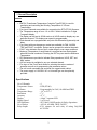
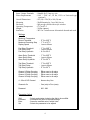
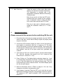
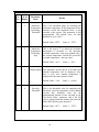
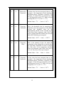
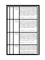
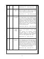
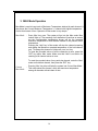
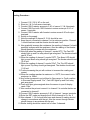
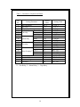
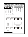
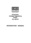
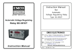
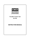
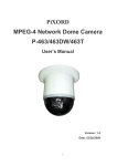
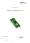
Instruction Manual For Transformer Temperature Controller EE-801 Instruction Manual For Transformer Temperature Controller EE - 801 EMCO ELECTRONICS Works : Unit No. 13, “Kedarnath”, Tungareshwar Industrial Complex No. 1, Village Sativali, Vasai (E), Dist : Thane – 401208. Tel.:(0250)2481783 / 1804, Fax : (0250)2481087 Email : [email protected] Office : 302, Vasan Udyog Bhavan, Senapati Bapat Marg, Opp. Phoenix Mill, Big Bazaar, Lower Parel (W), Mumbai – 400013. Tel.: (022)24902283 / 24923183, Fax : (022)24951024, Email : [email protected] South : Office 15, Wood Street, (1st Floor), Richmond Road, Bangalore – 560025 Tel.: (080)5570215, Fax : (080)5566606, Email : [email protected] 1 CONTENTS Sr. No. TITLE PAGE No. I GENERAL DESCRIPTION 3 II SPECIFICATIONS 4 III INDICATIONS & CONTROLS 6 IV OPERATING INSTRUCTIONS 8 V MODES OF OPERATION a. SET Mode b. CAL Mode c. MAX Mode 9 9 15 16 VI Testing Procedure 17 VII Trouble Shooting 18 VIII Package Contents 18 IX Table 1. – Parameters, Defaults and Limits 19 X Figure 1. – Input / Output Connections 20 XI Figure 1. – Simplified Block Diagram 20 XII Front Panel Controls & Indication 21 XIII Warranty 22 2 I. General Description Features • EMCO’s Transformer Temperature Controller Type EE-801 is used for monitoring and controlling the Winding Temperature of 3 Phase Transformers. • Four Input Channels are available for connecting four RTD (PT100) Sensors. • The Temperature range is from –10o to 250o C and is indicated on 3 digits 7-segment display. • The display can be kept in SCAN mode or in HOLD mode to display any one particular channel. The display scan speed is programmable. • Each channel has a programmable set point with differential (hysteresis) and delay. • Four relays with one-changeover contact are available for FAN, ALARM, TRIP and FAULT conditions. Relays can be grouped for selected channels. • FAULT relay indicates Sensor Open, under range or over range conditions. • Maximum Temperature of each channel is recorded and can be displayed when MAX mode is selected. Pressing the RST key can reset the Maximum Temperature. • LED indicators are provided to indicate Relay operations, HOLD, SET and MAX modes. • 4-20 mA output is available for any one selected channel. • Five keys on the Front Panel allows for selecting the various modes of operation as well as for programming the parameter values. • The unit is wall mountable and enclosed in a rugged metal cabinet. • The power supply is 110V/230V AC or Universal type can be optionally provided. II. Specifications No. of Channels Temperature Sensor Set Points Temperature Range Resolution Accuracy Display Display Speed LED Indicators No. of Relays Relay Output : 4 : RTD (PT100) : Programmable for FAN, ALARM and TRIP : –10o to 255o C : 1o C : ±2 o C : 4 digit 7 segment LED : 1 to 60 secs. : SET, MAX, HOLD modes, & Relay Operations : 4 (FAN, ALARM, TRIP, FAULT) : 1C/O contacts for each relay of rating 5A@240V AC/24VDC 3 Input / Output Terminals Power Requirements Overall Dimensions Mounting Enclosure Operating Temperature : Suitable for 2.5 mm sq. wire : 110V / 230V AC, 50 Hz, 15VA or Universal type (optional) : 195 (H) x 230 (W) x 100 (D) mm : Wall Mounting by 3 nos. M6 Screws : MS powder coated with acrylic window : 00 C to 500 C Weight : 3 KGs. (aprrox). Insulation : 2KV for 1 min between all terminals shorted and earth Settings Maximum Temperature Record Threshold Maximum Recording Step Display Speed : 00 C to 2500 C : 10 C to 200 C : 1 sec to 60 sec Fan Relay Threshold Fan Relay Delay Fan Relay Hysterisis : 10 C to 2500 C : 1 sec to 60 sec : 00 C to 200 C Alarm Relay Threshold Alarm Relay Delay Alarm Relay Hysterisis : 10 C to 2500 C : 1 sec to 60 sec : 00 C to 200 C Trip Relay Threshold Trip Relay Delay Trip Relay Hysterisis : 10 C to 2500 C : 1 sec to 60 sec : 00 C to 200 C Channel 1 Relay Grouping Channel 2 Relay Grouping Channel 3 Relay Grouping Channel 4 Relay Grouping : : : : 4 – 20 mA O/P Channel : None or Any One Channels On : One (min) to Four (max) Password : 000 - 999 Either none to all relays Either none to all relays Either none to all relays Either none to all relays Parameter Adjust Shift Increment Enter Set : : : : Selects and rotates clockwise the digit to be modified Increments the value of the selected digit Saves the modified value if within limits Selects the parameter to be adjsted 4 . Modes of operations Scan / Hold Mode : Toggles between Automatic Scan and Hold Mode of operation Set Mode : Allows configuration of all the parameters within permitted limits Max Mode : Shows the maximum temperature attained by each channel Current Max Mode : Shows the maximum temperature amongst all the four channels at the moment Calibration Mode : Allows the calibration of the system if needed Inputs Sensor Inputs : 3 Pin Terminal Block for 4 sensors each Mains : 3 Pin Terminal Block for connecting mains supply Outputs Relays : 3 Pin Terminal Block for 4 Relays each (Fan, Alarm, Trip and Fault) 4 – 20 mA output : 2 Pin Terminal Block for 4 – 20 mA output for any one channel 5 I. Indications & Controls Indications 1. 4 x 7 Segment Display : 4 seven segment displays are divided into two groups of 1 digit for “Ch. No.” and 3 digits for “Temperature” Display. Ch. No is used to indicate the channel no. The Temperature displays are used to display temperature of that particular channel in normal mode. In “SET” mode Ch. No. shows parameter no. and Temperature shows the value of that respective parameter. 2. Hold LED : ON when the system is in Hold mode. In Scan mode this LED is turned OFF. 3. Set LED : Turns ON when the system is in SET mode. 4. Max LED : Turns ON when the system is in MAX mode. Blinks when the system is in Current Max mode. 5. Fan LED : Turns ON when Fan Relay is energized. 6. Alarm LED : Turns ON when Alarm Relay is energized. 7. Trip LED : Turns ON when Trip Relay is energized. 8. Fault LED : Turns ON when Fault Relay is energized. Controls 1. Scan / Hold Key : Toggles the system between Scan and Hold mode. In Scan mode, the system displays the temperature of all the channels one after another in a sequence repeatedly. Each channel is displayed for the duration as programmed in the “Display Speed” parameter in SET mode. The default duration is 2 Seconds. In Hold mode, only one channel (channel currently being displayed) is locked on the display i.e. scanning of all channels is stopped. To change the channel in Hold mode Increment key is used. 6 2. Set / Reset Key : Takes the system in SET mode. Here all the parameters can be programmed according to the requirement. In SET mode this key is also used to increment the parameter number by one i.e. once the values of the current parameter are entered, this key is pressed to go to next parameter for programming. Pressing this key after last parameter, rollbacks to first parameter. To come out of the SET mode Enter key is pressed. Reset function is active only in the Max mode. In all other modes this function remains inactive. Reset key is used to reset all the recorded maximum temperature values to zero. 3. Shift / Cal Key : Shift function of this key is associated to SET mode only. In SET mode, while changing the parameter value, this key is used to shift to next digit. Blinking of digit indicates digit to be modified. The value of this digit can be incremented by INCR key. Cal key takes the system into auto calibration mode. Usually there is no need for calibrating the system, as it is factory calibrated. However if required the system can be calibrated easily. Each channel requires individual calibration. Pressing calibration key twice in succession takes the system out of this mode without calibrating. Also in calibration mode, if no key is pressed for two Min., system exits from calibration mode. 4. Incr Key : This key is used to increment the channel number in Scan and Hold Modes. In SET mode this key is used to increment the parameter values. Parameter value is changed by changing individual digits. For example, if the parameter value is to be changed from 199 to 200, individual digits need to be changed i.e. pressing increment key at 199 will not make it 200. Only the digit under consideration (blinking) will get incremented. If first digit is blinking (1), incrementing it will make the display 299. To switch to next digit shift key is used. Now middle digit will start blinking (9). Incrementing it will make the display 209. Similarly using shift key and increment key once again will make display 200. 7 5. Max / Enter Key : Takes the system in Max mode. Max mode displays the maximum-recorded temperature. The temperature is recorded only if the temperature exceeds the Maximum Recording Threshold value. Enter key is used to exit from the SET mode. Pressing Enter key accepts all the changes done in parameter values if within permitted limits, stores them and exits the SET mode. Enter key is also used in calibration mode to accept the calibration values for 0 0C and 200 0C. II. Operating Instructions Please connect all the sensors before switching ON the unit. 1. Ensure that the unit housing is properly grounded using the ‘EARTH’ screw on the side. Confirm that the Relay outputs are properly wired as given in the label. 2. Connect the RTD sensors properly as shown on the front plate (for more details of connections, refer fig 1 on page no. 20. Two white wires of the sensor go to the two-shorted terminals. The red wire goes to third terminal. Reversing the order of connection will generate the fault condition. Also any of the open sensor wire, generates fault condition. 3. If the supply is 230 V AC, Connect to pins 27 and 28 of terminal block (27 – Live, 28 – Neutral). If the supply is 110 V AC, Connect to Pins 28 and 29 (28 – Neutral, 29 – Live). 4. Power ON the unit. The display lights up showing channel no. 1 and its corresponding temperature for almost 7 seconds. This initial delay is due to the time required for the systems internal setup. Then the normal scanning of all the channels starts. The default display speed is 2 Sec for each channel. 5. Refer the Parameter Values in Table1 on page no. 19 to see if any changes are required in any parameter value. 6. If any change is required, Press the ‘SET’ key to enter the set mode. Make all the necessary changes to the parameter values as required. The operation of ‘SET’ mode is detailed in ‘SET mode operation’ on page no. 9. 8 7. If the temperature of any channel is more than any of the threshold values, the corresponding relay should get energized if it is grouped with that channel. Grouping details can be found in ‘SET mode operation’ on page no. 13. Also the Maximum values should get recorded if the temperature of any channel exceeds the ‘Maximum Recording Threshold’ value 8. 4-20 mA Current Output is available only for one channel. It is programmable in ‘SET’ mode. The Output current varies according to the temperature of the channel. 4 mA corresponds to 00 C and 20 mA correspond to 2500 C. Modes of Operation 1. SET Mode Operation Note : If the display goes off or unit becomes unfunctional in ‘SET’ mode, please Switch OFF and again Switch it ON. ‘SET’ mode allows user to program all the parameters as per ones requirements. To enter into the ‘SET’ mode, Press ‘SET’ key once. ‘SET’ LED lights up indicating that system is in SET mode. If none of the key is pressed within two minutes, the system automatically exits out of the ‘SET’ mode. During SET mode, Parameter values are displayed instead of normal temperature. However the relays continue to operate w.r.t. to Temperature. Once the ‘SET’ key is pressed, the system asks the user to enter the password. Password enhances the system security by restricting unauthorized access. Enter the correct password and press ‘SET’ key again to go for programming the parameters. If the password is wrong, it asks the user to enter the password again until the right password is entered. For exiting the ‘SET’ mode at any time press ‘ENT’ key. The first parameter is “Max Threshold”. The list of all the parameter and their details are given in table below. Once the parameter value is changed, press ‘SET’ key to go to next parameter setting. If no change is required, simply press the ‘SET’ key to bypass that parameter. After entering the required parameter values, press ‘ENT’ (enter) key. If the entered value is within permissible limits, it will be accepted and stored. Else system will prompt you to enter the value again. 9 Sr. No. Ch. No. Display Parameter Name 1 1 Maximum Temperature Recording Threshold Details This is the threshold point for recording the maximum temperature. If the temperature of any channel exceeds this threshold value, it gets recorded in the system. This parameter is user programmable. The default value for Max threshold is set to 1200 C. Default Value :1200 C. Limit : 0 - 2500 C 2 2 Maximum Temperature Recording Step This is the step in 0C in which the maximum temperature is recorded. i.e. the maximum recorded temperature value gets updated only if the current temperature exceeds the previously recorded temperature + the step value. Default Value : 100 C. 3 3 Display Speed This parameter decides the no of seconds each channel temperature will be displayed. After time is over, next channel temperature is displayed for the same amount of time. Default Value : 2 Sec. 4 4 Limit : 1 - 200 C Fan relay Threshold Limit : 1 – 60 Sec. This is the threshold value for energizing the Fan Relay. Once the temperature of any channel exceeds this threshold value for the predetermined amount of time (decided by the ‘Fan Relay Delay’ parameter, and if the Fan relay is grouped with that channel, then after the delay) the Fan Relay gets energized. Default Value : 800 C. 10 Limit : 1 - 2500 C 5 5 Fan relay Delay This is the amount of time for which the temperature of any channel has to remain above the Fan Relay Threshold in order to energize the Fan relay. If the temperature decreases below the threshold value before this time is over, the fan relay will not get energized. Default Value : 800 C. 6 6 Fan relay Hysterisis If Fan relay has been energized, then to deenergize it, the temperature of the transformer should drop below “Threshold – Hysterisis”. For example : if Fan Relay got energized at 100 0C, and Hysterisis is set to 5 0C, then it will get deenergized at 95 0C (100 0C – 5 0C). Default Value : 50 C. 7 7 Alarm relay Threshold Limit : 1 - 200 C Limit : 0 - 200 C This is the threshold value for energizing the Alarm Relay. Once the temperature of any channel exceeds this threshold value for the predetermined amount of time (decided by the ‘Alarm Relay Delay’ parameter, and if the Alarm relay is grouped with that channel, then after the delay) the Alarm Relay gets energized. Default Value : 1000 C. Limit : 1 - 2500 C 8 8 Alarm relay Delay This is the amount of time for which the temperature of any channel has to remain above the Alarm Relay Threshold in order to energize the Alarm relay. If the temperature decreases below the threshold value before this time is over, the Alarm relay will not get energized. Default Value : 5 Sec. 11 Limit : 1 – 60 Sec 9 9 Alarm relay Hysterisis If Alarm relay has been energized, then to deenergize it, the temperature of the transformer should drop below “Threshold – Hysterisis”. For example : if Alarm Relay got energized at 120 0 C, and Hysterisis is set to 5 0C, then it will get de-energized at 115 0C (120 0C – 5 0C). Default Value : 50 C. 10 A Trip relay Threshold Limit : 0 - 200 C This is the threshold value for energizing the Trip Relay. Once the temperature of any channel exceeds this threshold value for the predetermined amount of time (decided by the ‘Trip Relay Delay’ parameter, and if the Trip relay is grouped with that channel, then after the delay) the Trip Relay gets energized. Default Value : 1200 C. Limit : 1 - 2500 C 11 b Trip relay Delay This is the amount of time for which the temperature of any channel has to remain above the Trip Relay Threshold in order to energize the Trip relay. If the temperature decreases below the threshold value before this time is over, the Trip relay will not get energized. Default Value : 5 Sec. 12 C Trip relay Hysterisis Limit : 1 – 60 Sec If Trip relay has been energized, then to deenergize it, the temperature of the transformer should drop below “Threshold – Hysterisis”. For example : if Trip Relay got energized at 140 0C, and Hysterisis is set to 5 0C, then it will get deenergized at 135 0C (140 0C – 5 0C). Default Value : 50 C. 12 Limit : 0 - 200 C 13 D Ch. 1 relay grouping This setting decides which relays channel 1 will operate. For Fan relay to get energized by channel 1, it has to be grouped with channel 1. If ungrouped, fan relay will not get energized even if the temperature of channel 1 exceeds the Fan Relay Threshold. Similarly Alarm and Trip Relays also have to be grouped with Channel 1 in order for their operation w.r.t. channel 1 Default Value : 123. 14 E Ch. 2 relay grouping This setting decides which relays channel 2 will operate. For Fan relay to get energized by channel 2, it has to be grouped with channel 2. If ungrouped, fan relay will not get energized even if the temperature of channel 2 exceeds the Fan Relay Threshold. Similarly Alarm and Trip Relays also have to be grouped with Channel 2 in order for their operation w.r.t. channel 2 Default Value : 123. 15 F Ch. 3 relay grouping r Ch. 4 relay grouping Limit : None to All This setting decides which relays channel 3 will operate. For Fan relay to get energized by channel 3, it has to be grouped with channel 3. If ungrouped, fan relay will not get energized even if the temperature of channel 3 exceeds the Fan Relay Threshold. Similarly Alarm and Trip Relays also have to be grouped with Channel 3 in order for their operation w.r.t. channel 3 Default Value : 123. 16 Limit : None to All Limit : None to All This setting decides which relays channel 4 will operate. For Fan relay to get energized by channel 4, it has to be grouped with channel 4. If ungrouped, fan relay will not get energized even if the temperature of channel 4 exceeds the Fan Relay Threshold. Similarly Alarm and Trip Relays also have to be grouped with Channel 4 in order for their operation w.r.t. channel 4 13 Default Value : 123. 17 o 4-20 mA O/p Ch. Selects the Channel for which 4-20 mA output will be available. If 4-20 mA output is not required, program this parameter to 000. Default Value : Ch. 1. 18 n Ch. On/Off Limit : None to All Limit : None or any one This Setting decides which Channels will be active. For e.g. if one requires only 2 Channels instead of 4, he can delete the other 2 channels (deleting the channel means neither they will be displayed nor control the operation of any relay). At any given time, at least one channel should be kept On i.e. all the 4 channels cannot be deleted at the same time. Default Value : all ch. On.. Limit : None to All 19 u Default settings Restores all the parameter to their default values. Note: Password and Maximum recorded temperature values are not restored. For resetting the Maximum recorded temperature values, press ‘RST’ button in ‘Max’ mode. Default Value : No. 20 c Password Limit : No or Yes Allows changing password. Password can be set to any number from 000 to 999. While changing password special care must be taken. Please write down the new password at safe place because once the parameter rollsover, next time the actual password is not displayed but only “---“ is displayed for protection purpose. Default Value : 000. 14 Limit : 000 - 999 2. CAL Mode Operation This is an “Auto Calibration Mode”. In general, there is no need to calibrate the system, as it is already factory calibrated before shipping. But in case if one wants, it can be easily calibrated in two steps. Each channel requires individual calibration. If the channel calibration does not succeed in first attempt, calibrate it twice. Procedure Calibration procedure has two steps. 0 oC Calibration : 1. Short pin 1 and 2 of Terminal block provided for RTD Sensor of respective channel. See figure 1. 2. Connect 100 Ω resistor between pin 2 and 3. 3. Press ‘CAL’ button to enter Calibration mode. The display shows channel no for which the calibration is being done in ‘CH. No’ and “000” in ‘Temperature’. 4. Wait for 5 sec. 5. Press ‘ENT’ key. The ‘Temperature’ display will show 200 now. 200 0C Calibration : 1. Remove 100 Ω resistor and connect 175.84 Ω in place of it. 2. Wait for 5 sec. 3. Press ‘ENT’ key 4. ‘Temperature’ Display will show “Out”. 5. Press ‘CAL’ key to exit Calibration mode. 6. If calibration is not successful, recalibrate it. Veification : After calibrating the unit please verify that the calibration was successful. 1. Short pin 1 and 2 of Terminal block provided for RTD Sensor of respective channel. See figure 1. 2. Connect 100 Ω resistor between pin 2 and 3. 3. The Display should show “000”. 4. Now connect 175.84 Ω resistor in place of 100 Ω resistor. 5. The Display should show “200” ± 1. 6. If readings are not proper, that means calibration was not successful. In such case recalibrate it. 15 3. MAX Mode Operation Max Mode is used to keep track of Maximum Temperature attained by each channel. It also shows the Current Maximum Temperature i.e. channel with highest temperature of all at that instant of time. Operation of Max mode is very simple. Max Mode : Press ‘Max’ key once. The system will go into the Max mode. Max Led will light up. The scanning of all channels will continue as normal but the corresponding temperature shown will be the recorded maximum temperature of that channel instead of the present actual temperature. Pressing the ‘Hold’ key in Max mode will stop the channel scanning and display the Maximum recorded temperature of the hold channel only. To change the channel in Hold mode, use ‘Incr’ key. To reset the recorded values of all the channels at once, press the ‘RST’ key within ‘Max’ mode. Make sure that ‘Hold’ is not active for resetting of all channel values at once. To reset the recorded value of any particular channel, enter the ‘Max’ mode and hold that channel, then press the ‘RST’ key. Current : Pressing ‘Max’ key twice will take the system into Current Max Mode. This mode shows the channel, which has maximum temperature Max Mode among all channels at that instant of time. 16 Testing Procedure : 1. 2. 3. 4. Connect 110 / 230 V AC on the unit. Short pin 1 & 2 of all sensor terminals. Connect 100 Ω resistor across pin 2 & 3 of sensor 2, 3 & 4 terminals. Connect 100 Ω pot with 100 Ω resistor in series across pin 2 & 3 of sensor 1 terminals. 5. Connect 100 Ω resistor with Ameter in series across 4-20 mA output terminals. 6. Switch on the supply. 7. Note the readings of channel 2, 3 & 4 should be zero. 8. Keep the pot connected to channel 1 at its minimum position. Channel 1 should read zero and the Ameter should read 4 mA. 9. Now gradually increase the resistance, the reading of channel 1 should gradually increase with the resistance. Also the reading of the Ameter should gradually increase with the resistance. 10. Note that when the reading of channel 1 equals 800C, The Fan LED should light up and Fan relay should get energized. The Ameter should read 9.12 mA. 11. When the reading of channel 1 equals 1000C, The Alarm LED should light up and Alarm relay should get energized. The Ameter should read 10.40 mA. 12. When the reading of channel 1 equals 1200C, The Trip LED should light up and Trip relay should get energized. The Ameter should read 11.68 mA. 13. Furthur increasing the pot will continue to increase the reading and current. 14. When the reading reaches its maximum i.e. 2500C, the current is also maximum i.e. 20mA. 15. Any furthur increment in pot will lead to Over range i.e. Fault conditon. In this case Display reads “Ovr”, Fault LED lights up and Fault relay gets energized. 16. Fault relay also gets energized when the sensor is open & display reads “Opn”. 17. Now remove the pot and connect it to channel 2 in a similar fashion as connected to channel 1. 18. Connect 100 Ω resistor across pin 2 & 3 of channel 1 sensor terminals. 19. Enter the SET mode and change the 4-20mA channel to Ch. No. 2 20. Now channel 1, 3 & 4 should read zero and channel 2 reading should change in accordance with the pot. Also the current through Ameter should change in accordance with the pot. 21. Similar testing should be carried out for other 2 channels. 17 Trouble Shooting : Sr. No. Symptom 1 No Display 2 Fault LED continuously On Remedy Check mains supply is properly connected. Power switch is switched on. Check if any sensor is open or short. Also make sure that all the sensors are properly connected as shown. Wrong sensor connection leads to fault condition. Package Contents : On receiving the Package please ensure that the package contains the following items 1. TTC Unit 2. User Manual 3. Mounting Accessories 4. PT-100 Sensor 18 1 No. 1 No. 3 Nos. 3 Nos. Table 1 - Parameters, Defaults and Limits Ch. No. 1 2 3 4 5 6 7 8 9 A b C D E F r o n u c Setting Parameter Max Threshold Max Step Display speed Fan relay Alarm relay Trip relay Relay Grouping* Threshold Delay Hysterisis Threshold Delay Hysterisis Threshold Delay Hysterisis Ch. 1 Ch. 2 Ch. 3 Ch. 4 4-20 mA O/p Ch. Ch. On/Off Default settings Password Default value 120 0C 10 0C 2 Sec 80 0C 5 Sec 5 0C 100 0C 5 Sec 5 0C 120 0C 5 Sec 5 0C 123 123 123 123 Ch. 1 All On n 000 * 1 – Fan Relay, 2 – Alarm Relay, 3 – Trip Relay. 19 Setting Limit 0 - 250 0 C 1 - 200 C 1 - 60 Sec 1 - 250 0 C 1 - 60 Sec 0 - 200 C 1 - 250 0 C 1 - 60 Sec 0 - 200 C 1 - 250 0 C 1 - 60 Sec 0 - 200 C 000 - 123 000 - 123 000 - 123 000 - 123 Any One Ch. Min. One On y/n 000 - 999 1 2 3 Sensor 1 Sensor 2 Sensor 3 Sensor 4 1 2 1 2 3 1 2 3 1 2 3 1 2 3 1 2 3 110 / 230 V AC 1 2 3 Fault Relay 1 2 3 15 16 17 18 19 20 21 22 23 24 25 26 27 28 29 Trip Relay 1 2 3 13 14 Alarm Relay 7 8 9 10 11 12 Fan Relay 4 5 6 4 - 20 mA Output 1 2 3 Figure 1. - Input / Output Connections RTD Sensor Input Buffer Stage Power Supply Switches Micro Controller +5V DC +12V DC Constant Current Source 4-20 mA Output Relays 230V AC Figure 2. – Simplified Block Diagram 20 Displays and LEDs 21 Warranty : This product from EMCO ELECTRONICS is warranted against defects in materials and workmanship for a period of 12 months from the date of dispatch to the first Buyer / purchaser of this equipment, this being essentially limited by warranties given to EMCO ELECTRONICS on the component used in equipment. During the warranty period EMCO ELECTRONICS will at its option, either repair or replace the product which proves to be defective provided the product has been used with reasonable care and in accordance with the manuals / product specification. Consequently this warranty shall also not apply to defects/damages in transit or resulting from misbehaving, misuse, unauthorized modifications or repairs operations outside the environmental, electrical and/or other specification, improper or inadequate maintenance of the product, or site conditions as required/recommended and damages arising from accidental or abnormal causes. The warranty period for items repaired/replaced shall not exceed the period for which the equipment was originally warranted and also the liability of EMCO ELECTRONICS to the purchaser shall not in any case, exceed the original purchase price of the equipment. For warranty service or repair, the equipment must be returned to EMCO ELECTRONICS securely packed on Freight paid basis and accompanied by a certificate stating that the equipment is being returned for warranty repairs and also note giving details of the purchase (Purchaser’s Name. and address, invoice No. and Date of purchase) and details of the equipment failure, faults conditions, other useful information to facilitate early repair/rectification or the equipment. Return of the equipment duly repaired can be arranged on payment of the packing and forwarding charges together with any other taxes, duties, other miscellaneous expenses incurred alternatively the purchaser may arrange to collect the equipment from EMCO ELECTRONICS. In case the repairs are not covered under warranty, the charges to the same must also be paid before collection of the equipment. Our engineer’s services are available at site for instruments during warranty or out of warranty period, on chargeable basis. Details of which are available on request. In the interest of development and improvement EMCO ELECTRONICS reserve the right to amend without notice details contained in this publication. EMCO ELECTRONICS will accept no legal liabilities for any errors, omissions or amendments. 22