1
equal to the resistive drop to make the voltage at the load end equal to the regulated
voltage. When the polarity is negative `n’, the voltage drop is added to lower the voltage.
In normal situation the positive polarity is selected.
The %X setting gives the reactive drop which is in phase quadrature to the PT voltage.
The positive `P’ drop gives lagging compensation and negative `n’ drop gives leading
compensation. Since the reactive compensation is in quadrature, its effect on AVR is very
less, but similar to %R compensation, i.e. positive compensation raises the voltage and
negative compensation lowers the voltage.
NOTE :
1. Switch off the CT current or short CT before removing the unit from the panel.
2. When LDC is not required set %R and %X values to zero.
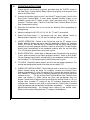
INSPECTION PROCEDURE
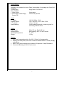
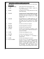
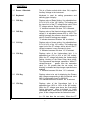
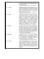
1. Connect 110V AC supply to Auxiliary Input pins 1, 2 on Rear Panel Terminal Block
and 110V AC PT supply through a variac to pins 3, 4 on Rear Panel Terminal
Block
2. Switch on and feed 1Ampere AC current through the pins 11, 12 on Rear Panel
Terminal Block.
3. Set NVA = 110, LS and RS = 2%, %R and %X = 0.
4. Varry the variac voltage to read 110.0V on the display.
5. Set %R to P 5%. `Raise’ indication should come and PT voltage is reduced by 5%
(104.5V).
6. Change the %R polarity to `n’. `Lower’ indication should come and the display
reads 5% more (115.5V)
7. Set LS and RS to 1% and %R back to zero. Set %X to P20% `Raise’ indication
should come.
8. Change %X polarity to `n’. `Lower’ indication should come.
Note: Since the %X compensation is in quadarature, the effect is less.
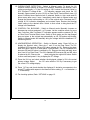
2. Auxiliary Fail Relay
This option consists of a relay which operates on 110V AC. The relay is energised
as long as the Auxiliary Supply to the unit is present. When the auxiliary supply fails the
contacts on pins 25, 26 of Rear Panel Terminal Block close to operate an alarm
(external).
16