1
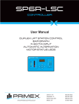
SP6R CONTROLLER User Manual DIGITAL DISPLAY WITH BARGRAPH 6 RELAY OUTPUTS OUTPUT STATUS LED 4-20mA INPUT WWW.PRIMEXCONTROLS.COM Ashland, OH 800-363-5842 Clearwater, FL 800-349-1905 Detroit Lakes, MN 888-342-5753 Milford, OH 513-831-9959 TABLE OF CONTENTS REVISION B • Firmware Revision B2.01 Specifications ............................................................................................................................. 2 Introduction ................................................................................................................................. 3 Warnings .................................................................................................................................... 4 Installation & Dimension Data ................................................................................................. 5-7 Electrical Connections ................................................................................................................ 8 Function Keys / Displays ............................................................................................................ 9 Setting Up Levels and Simulation ....................................................................................... 10-11 Configuration ....................................................................................................................... 12-13 Configuration Mode Parameters .............................................................................................. 14 Run Mode Parameters ............................................................................................................. 15 Notes ........................................................................................................................................ 16 WWW.PRIMEXCONTROLS.COM PRIMEX™ SP6R Level Controller User Manual SPECIFICATIONS INPUT TYPE 4-20 mA signal. INPUT IMPEDANCE 100 ohms. INPUT RESOLUTION 12 - bits, 0.1% of full scale. SAMPLING CYCLE TIME 100 mS. AVERAGING 8 consecutive samples. ACCURACY 0.5% of full scale. EXCITATION VOLTAGE 24 VDC, 30 mA available for loop powered transducers. RELAY OUTPUTS Six programmable relay outputs with LED indication. “Form C” (SPDT) contacts: rated at 10A at 240 VAC. LEVEL DISPLAY Eight character alpha-numeric LED for process value and program parameters. The display is avionics grade and is sharp and clear, even in direct sunlight from 10 feet away. POWER 24 VDC (+/- 10%). 200 mA nominal, 400 mA max. OPERATING TEMPERATURE -15oC to 70oC (0oF to 150oF) at up to 0-90% RH non-condensing. ENCLOSURE RATING Front Panel: IEC Standard IP54 (with additional gasket) for indoor use. Rear Case: IEC Standard IP20. BAR GRAPH 20 segment bar graph display for process value. Each bar represents 5% of full scale. PRIMEX™ 2 SP6R Level Controller User Manual SP6R LEVEL CONTROLLER INTRODUCTION The SP6R level controller is a simple, easy-to-use microprocessor-based controller which monitors any 4-20 mA signal. It has six programmable relay outputs that can be used for control and alarm. The transducer input zero and span are fully configurable. A simulation mode allows the user to test the set-points and relay operation. The standard SP6R level controller contains (see Figure 2 on page 5 of this manual): • one SP6R level controller • two mounting brackets for panel mounting • a three pin power supply connector block (P1) • a five pin transducer connector block (P2) • a 18 pin relay output connector block (P3) The SP6R-N4X version includes a controller mounted within a NEMA 4X enclosure with a pre-wired power supply and terminal blocks. PRIMEX™ 3 SP6R Level Controller User Manual WARNINGS Failure to read and understand the information provided in this manual may result in personal injury or death, damage to the product or product failure. Please read each section in its entirety and be sure you understand the information provided in the section and related sections before attempting any of the procedures or operations given. Failure to follow these precautions could result in serious injury or death. Keep these instructions with warranty after installation. This product must be installed in accordance with National Electrical Code, ANSI/NFPA 70 so as to prevent moisture from entering or accumulating within the controller housing. See additional specifications on page 14 of this manual. ELECTRICAL SHOCK HAZARD Disconnect power before installing or servicing this product. A qualified service person must install and service this product according to applicable electrical codes. • Do not install in area with: excessive or conductive dust, corrosive or flammable gas, moisture or rain, excessive heat, regular impact shocks or excessive vibration. • • • • • • Do not place in water or let water leak onto the controller. Do not allow debris to fall inside the unit during installation. Double-check all the wiring before turning on the power supply. Do not touch live wires. Stay as far as possible from high-voltage cables and power equipment. Leave a minimum of 10 mm space for ventilation between the top and bottom edges of the controller and enclosure walls. EXPLOSION OR FIRE HAZARD Do not use this product with flammable liquids. Do not install in hazardous locations as defined by National Electrical Code, ANSI/NFPA 70. PRIMEX™ 4 SP6R Level Controller User Manual INSTALLATION & DIMENSIONAL DATA FIGURE 1 Dimensions and panel cut-out. Dimensions are indicative and may be subject to change without notification. PRIMEX™ 5 SP6R Level Controller User Manual PRIMEX™ 6 SP6R Level Controller User Manual cut along dotted line 8.6” (218 mm) PANEL CUT OUT TEMPLATE FOR SP6R LEVEL CONTROLLER 4 7/16” (112 mm) INSTALLATION & DIMENSIONAL DATA FIGURE 2 Standard SP6R level controller kit. PRIMEX™ 7 SP6R Level Controller User Manual ELECTRICAL CONNECTIONS FIGURE 3 Wiring diagram, back view - with a submersible pressure transducer. 1. POWER (Terminal P1) Connect power to terminal 1 and 2: the unit requires 24 VDC (+/- 10%). 2. TRANSDUCER (Terminal P3) For loop powered transducers (2 wire) connect power conductor to terminal 1 and 2. If the cable is protected with an overall shield, connect the shield to terminal (3). Terminal 4 and 5 must be connected if an output follower is not required. If no valid input is present, the controller will display SENSOR and all outputs will be de-energized. NOTE: To avoid ground loops, the shield of the signal cable must only be grounded at one end. 3. OUTPUT RELAY CONNECTIONS The relay outputs are rated up to 10 A (resistive) at 240 VAC, fuse protection is required individually or as a group. PRIMEX™ 8 SP6R Level Controller User Manual FUNCTION KEYS / DISPLAYS 00000000 SET POINTS 6 programmable set points status LED. Form C (SPDT) contacts: rated at 10A at 240 VAC. KEYPAD GRAPH Arrow keys are used 20 segment bar graph to navigate through the display for process value. configuration and used for Each bar represents 5% adjusting set points. of full scale. BAR LEVEL DISPLAY Eight character alphanumeric LED for process value display and program parameters. LEFT AND RIGHT ARROW KEYS are used to navigate through the menu items. These arrow keys can also be used to back out when in editing and simulation mode. ENTER KEY is used for selecting a menu item for editing. This key is also used after a valued has been edited to store in memory. UP AND DOWN ARROW KEYS is used to increase or decrease the current value being edited. NOTE: The display automatically returns to “level” after 20 seconds of inactivity, regardless of where it was left. Pressing once will increment the current value by one unit. Pressing and holding will begin repeatedly incrementing after a short delay. If the operator continues to hold the key, the value continues to increment at a faster rate. PRIMEX™ 9 SP6R Level Controller User Manual SETTING UP LEVELS AND SIMULATION LEVEL DISPLAY FLASHING SELECT STORE EDIT FIGURE 4 Example of how to move from the level display screen through each set-point and to change set-point 2. Continued on next page... PRIMEX™ 10 SP6R Level Controller User Manual ...Continued from previous page FLASHING LEVEL DISPLAY The adjustable ON and OFF function allows for an individual hysteresis or differential setting of each setpoint. For an emptying application, the ON set-point must be greater than the OFF set-point. For a filling application, the ON set-point must be less than the OFF set-point (Refer to FIGUIRE 5). NOTE: For proper operation of the SP6R controller, the ON and OFF set-points must not be set to the same value. FIGURE 5 PRIMEX™ 11 SP6R Level Controller User Manual CONFIGURATION To enter the configuration mode, simultaneously press the LEFT and RIGHT arrow key and hold for three (3) seconds with the unit powered ON. NOTE: Eight (8) seconds of inactivity (no keys pressed) will terminate the configuration menu and exit back to the run menu. The first item in the configuration menu is the UNITS selection. Use the LEFT or RIGHT arrow keys to navigate through all the items in this menu. UNITS Select the unit of measure display after the process value. FT = Feet IN = Inches CM = Centimeters % = Percentage oC = Degrees Celsius oF = Degrees Fahrenheit PS = Pound Per Square Inch (PSI) BR = Bar NONE = Blank, No Units Displayed When you are at the item you wish to edit, press the ENTER key and the original value for the item selected will flash. Use the UP and DOWN arrow keys to change to your desired value and press ENTER. NOTE: The edited value will not be saved until the ENTER key is pressed. 4 mA Set the value displayed when the signal value is equal to 4 mA (zero). The default value is zero. 20 mA Set the value displayed when the signal value is equal to 20 mA (span). The default value is 10.0. BAR MIN This value set the level for which all bars on the bar graph will turn OFF. BAR MAX will This value set the level for which all bars on the bar graph turn ON. OFFSET An offset value can be added or subtracted to bring the display value to zero at atmospheric pressure. If you are using a submersible pressure transducer, the level readout at atmospheric pressure (out of the wet well) should be zero. If it is not, add or subtract (negative) a value to bring the display to zero. Check the level readout to verify it is zero. If not, try changing the offset again. PRIMEX™ 12 SP6R Level Controller User Manual 0005.30ft + LEVEL DISPLAY HOLD BOTH ARROW KEYS FOR 3 SECONDS 000UNITS 000040MA 000200MA 00 1 1.50ft 0023.00ft 0BAR0MIN 0BAR0MAX 00offset 000UNITS FIGURE 6 Use the right or left arrow keys to navigate through these menu items. Begin with UNITS, 4 mA, 20 mA, BAR MIN, BAR MAX, OFFSET, and back to UNITS. NOTE: Eight (8) seconds of inactivity (no keys pressed) will terminate the configuration menu and exit back to the run menu. PRIMEX™ 13 SP6R Level Controller User Manual CONFIGURATION MODE PARAMETERS MIN OOOUNITS MAX FT, IN, CM, %, oC, oF, PS, BR, (NONE) DEFAULT USER FT OOOO4OMA 0.0 999.9 0.0 FT OOO20OMA 0.0 999.9 10.0 FT OBAROMIN 0.0 999.9 0.0 FT OBAROMAX 0.0 999.9 10.0 FT OOOFFSET -9.9 9.9 0.0 FT NOTES PRIMEX™ 14 SP6R Level Controller User Manual RUN MODE PARAMETERS USER VALUE MIN MAX DEFAULT LEVEL DISPLAY -99.9 999.9 SENSOR on invalid input signal OOSP1OON 0.0 999.9 1.5 FT OSP1OOFF 0.0 999.9 1.0 FT OOSP2OON 0.0 999.9 2.5 FT OSP2OOFF 0.0 999.9 2.0 FT OOSP3OON 0.0 999.9 4.5 FT OSP3OOFF 0.0 999.9 4.0 FT OOSP4OON 0.0 999.9 6.5 FT OSP4OOFF 0.0 999.9 6.0 FT OOSP5OON 0.0 999.9 8.5 FT OSP5OOFF 0.0 999.9 8.0 FT OOSP6OON 0.0 999.9 9.5 FT OSP6OOFF 0.0 999.9 9.0 FT SIMULATE PRIMEX™ USER FUNCTION 4 mA value in 20 mA value in configuration configuration 15 SP6R Level Controller User Manual NOTES PRIMEX™ 16 SP6R Level Controller User Manual ASSEMBLED IN THE USA WWW.PRIMEXCONTROLS.COM Ashland, OH 800-363-5842 Clearwater, FL 800-349-1905 Detroit Lakes, MN 888-342-5753 Milford, OH 513-831-9959 PN 1038547A REV 09/13 © 2013 SJE-Rhombus® PRIMEX™ is a trademark of SJE-Rhombus®