1
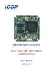
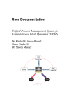
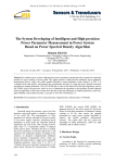
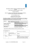
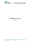
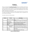
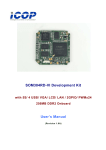
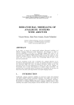
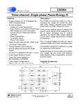
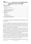
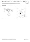
ATT7053BU User Manual(210-SD-139)
ATT7053BU
User Manual
http://www.hitrendtech.com
Hi-Trend Technology (Shanghai) Co., Ltd.
V0.1
1/50
ATT7053BU User Manual(210-SD-139)
Table of Contents
1.
2.
3.
4.
5.
6.
General Description ........................................................................................................................................... 5
Block Diagram................................................................................................................................................... 6
Pins Description................................................................................................................................................. 6
3.1.
PIN CONFIGURATION.................................................................................................................... 6
3.2.
PIN Function Descriptions................................................................................................................. 7
3.3.
PIN status when be reset.................................................................................................................... 8
3.4.
The definition of I/O high or low level.............................................................................................. 8
3.5.
Electric Specification....................................................................................................................... 10
ATT7053BUModule Description .................................................................................................................... 11
4.1.
ADC module.................................................................................................................................... 11
4.2.
VREF Parameter.............................................................................................................................. 11
4.3.
System power check ........................................................................................................................ 11
4.4.
EMU module function ..................................................................................................................... 12
4.4.1.
wave sampling function ........................................................................................................... 12
4.4.2.
Power\RMS\Frequency ............................................................................................................ 12
4.4.3.
Power\Rapid pulse................................................................................................................... 13
4.4.4.
EMU state instruction.............................................................................................................. 14
4.4.5.
Current channel 2 gain calibration ......................................................................................... 14
4.4.6.
Interruption output................................................................................................................... 14
SPI communication function ........................................................................................................................... 14
5.1.
General description .......................................................................................................................... 14
5.2.
ATT7053BU SPI interface introduction .......................................................................................... 14
5.3.
ATT7053BU SPI interface communication definition..................................................................... 14
5.4.
SPI communication waveform......................................................................................................... 15
5.5.
The example of ATT7053BU SPI communication .......................................................................... 16
5.6.
ATT7053BU communication interface error definition................................................................... 17
5.7.
ATT7051A/53A/59 checksum ......................................................................................................... 17
5.8.
ATT7053BU SPI I/O status ............................................................................................................. 17
5.9.
Communication CS pull-down mode............................................................................................... 17
Register function.............................................................................................................................................. 18
6.1.
Measurement Parameter Registers List ........................................................................................... 18
6.2.
Measurement Parameter Registers Explain ..................................................................................... 18
6.2.1.
ADC waveform register(SPLI1,SPLI2,SPLU) ......................................................................... 18
6.2.2.
RMS value output((I1Rms, I2Rms, URms) ......................................................................... 19
6.2.3.
Voltage frequency measurement: ............................................................................................. 20
http://www.hitrendtech.com
Hi-Trend Technology (Shanghai) Co., Ltd.
V0.1
2/50
ATT7053BU User Manual(210-SD-139)
6.2.4.
Power parameter output(PowerP1, PowerQ1, PowerS) .................................................... 20
6.2.5.
Energy parameter output(EnergyP, EnergyQ, EnergyS) .................................................... 21
6.2.6.
Power parameter output(PowerP2,PowerQ2) ........................................................................ 22
6.2.7.
Data backup register(BCKREG) ............................................................................................. 22
6.2.8.
Communication checksum register(Ccheck)............................................................................ 23
6.2.9.
Parameter checksum register(Scheck)..................................................................................... 23
6.2.10. EMU Status Register(EMUSR) ........................................................................................... 23
6.2.11. System Status Register(SYSSTA) .............................................................................................. 24
6.2.12. Device IDCode......................................................................................................................... 25
6.3.
Measurement Parameter Registers List ........................................................................................... 26
6.4.
Calibration Register Explain............................................................................................................ 27
6.4.1.
EMUIE Interrupt Enable Register(EMUIE) ............................................................................ 27
6.4.2.
EMU Interrupt Flag Register .................................................................................................. 28
6.4.3.
Written-protect Register(WPCFG) .......................................................................................... 29
6.4.4.
Soft-reset Register(SRSTREG)................................................................................................. 29
6.4.5.
EMU configuration register(EMUCFG).................................................................................. 30
6.4.6.
Clock configuration register(FreqCFG).................................................................................. 32
6.4.7.
Module Control Register( ModuleEn) ..................................................................................... 33
6.4.8.
ADC switch register (ANAEN)................................................................................................. 34
6.4.9.
Output pin configuration register(IOCFG) ............................................................................. 34
6.4.10. Active Power calibration of channel1(GP1) ...................................................................... 35
6.4.11. Reactive Power calibration of channel1(GQ1) .................................................................. 35
6.4.12. Apparent Power calibration of channel1(GS1) .................................................................. 36
6.4.13. Active Power calibration of channel2(GP2) ...................................................................... 36
6.4.14. Reactive Power calibration of channel2(GQ2) .................................................................. 36
6.4.15. Apparent Power calibration of channel1(GS2) .................................................................. 37
6.4.16. Reactive Phase calibration(Phase1) .................................................................................. 37
6.4.17. ADC Channel Gain Register ADC通道增益(ADCCON).................................................. 37
6.4.18. Gain of current channel2(I2Gain) ........................................................................................... 38
6.4.19. AC offset calibration register of current channel1................................................................... 39
6.4.20. DC offset calibration register of current channel2(I2Off) ....................................................... 39
6.4.21. DC offset calibration register of voltage channel (UOff).................................................. 39
6.4.22. No-load/startup Setup .............................................................................................................. 40
6.4.23. Pulse Frequency setting register(HFConst) ............................................................................ 40
6.4.24. Tampering threshold value |P| or IRMS range setting up among channels (Chk): ................. 40
6.4.25. Tampering detecting threshold value |P| or IRMS setting(IPTAMP)....................................... 41
6.4.26. Small signal active Power calibration of channel1(P1OFFSET)............................................ 41
6.4.27. Small signal active Power calibration of channel2(P2OFFSET)............................................ 42
6.4.28. Small signal reactive Power calibration of channel1(Q1OFFSET) ........................................ 42
http://www.hitrendtech.com
Hi-Trend Technology (Shanghai) Co., Ltd.
V0.1
3/50
ATT7053BU User Manual(210-SD-139)
7.
8.
6.4.29. Small signal reactive Power calibration of channel2(Q2OFFSET) ........................................ 42
6.4.30. RMS value offset calibration register of current channel1(I1RMSOFFSET) .......................... 43
6.4.31. RMS value offset calibration register of current channel1(I1RMSOFFSET) .......................... 43
6.4.32. Zero-Crossing current threshold value setting-up register(ZCrossCurrent)............................ 43
6.4.33. PQ mode’s phase calibration register(GPhs1) ........................................................................ 44
6.4.34. PQ mode’s phase calibration register(GPhs2.......................................................................... 44
6.4.35. Fast pulse counter.................................................................................................................... 44
6.4.36. The process of recommending calibration ............................................................................... 45
Application Schematic..................................................................................................................................... 49
Package Diagrams ........................................................................................................................................... 50
http://www.hitrendtech.com
Hi-Trend Technology (Shanghai) Co., Ltd.
V0.1
4/50
ATT7053BU User Manual(210-SD-139)
1. General Description
The ATT7053BU is a single-phase multi-function energy measurement chip with SPI serial interface .
Wide supply voltage operation :4.5V-5.5V.
Recommends 6MHz crystal oscillator.
Feature:
z
z
z
z
z
z
z
z
z
z
z
Three 19 bit sigma-delta ADCs
Over Dynamic range of 3000:1.
Supply active power and reactive power of two channels simultaneously.
Support active, reactive, apparent power measurement and energy pulse output.
Simultaneously supply RMS measurement of three ADC channels, and the frequency of voltage channel
Support SPI communication manner
Support zero-crossing interrupt, sampling interrupt, energy pulse interrupt and calibration interrupt.
Less than 4.5 mA current supply in normal mode, less than 2mA current supply in burglar-proof electricity
and voltage-depreciation mode.
Support the power supply monitoring and battery monitoring.
LBOR
SSOP 24(ATT7053BU)
http://www.hitrendtech.com
Hi-Trend Technology (Shanghai) Co., Ltd.
V0.1
5/50
ATT7053BU User Manual(210-SD-139)
2. Block Diagram
2 阶ADC
DEC filter
PGA
I2IN+
I2IN-
2 阶ADC
PGA
I1IN+
I1IN-
PGA
VIN+
VIN-
2 阶ADC
DEC filter
QF/SF
EMU
SDO
SDI
SCLK
Register
VREFO
PF
Pulse
output
DEC filter
Voltage
Reference
General
Interface
CS
TEST
Test2
Reset
IRQ/ZX
Power
Monitor Unit
DVCC AVCC
Clock
Generator
CLKIN CLKOUT
Figure 2-1 Block Diagram for 7053BU
3. Pins Description
3.1. PIN CONFIGURATION
(1) ssop24, Three ADCs+ two CFs
http://www.hitrendtech.com
Hi-Trend Technology (Shanghai) Co., Ltd.
V0.1
6/50
ATT7053BU User Manual(210-SD-139)
3.2. PIN Function Descriptions
ATT7053BU Mnemonic
1
DVDD
2
RST\
Descriptions
Digital power supply;4.5v~5.5v
3
VDD1P8
Digital 1.8V voltage output.This pin should be connected
with a 1uF capacitor in parallel with a ceramic 100nF
capacitor.
4
5
6
Test\
AVCC
V3P
Test mode . This pin should be pulled up to DVDD .
7
8
V3N
V2P
Negative input for voltage channel.
9
10
V2N
V1P
Negative input for current channel 2.
11
12
V1N
VREF
Negative input for current channel 1.
13
AGND
The analog ground is the ground reference for all analog
circuitry.
14
15
16
17
Test2
QF/SF
PF
IRQ\
pull-up input pin.(default)
18
19
20
21
22
23
24
SPICS
SPIDI
SPIDO
SPICLK
XTALI
XTALO
DGND
SPI selection signal
http://www.hitrendtech.com
ATT7053BU reset, effected in low voltage.This pin is
defined as default internal force pull-up.When above
200us low voltage,the device is reset.
Analog power supply input; 4.5v ~ 5.5v
Positive input for voltage channel. The maximum input
signal level is ±700mVp.
Positive input for current channel 2.The maximum input
signal level is ±700mVp.
Positive input for current channel 1.The maximum input
signal level is ±700mVp.
ADC reference voltage output, the nominal value is 2.5v.
This pin should be externally tied to 0.1uF capacitor
Q Pulse output(Default) / S Pulse output
P Pulse output
Interrupt signal output, the output is “0” when
interruption is produced
SPI serial data input
SPI serial data output
SPI serial clock, this pin is floating
System oscillator input(typical: 6MHz)
System oscillator output(typical: 6MHz)
This pin provides the ground reference for the digital
circuitry.
Hi-Trend Technology (Shanghai) Co., Ltd.
V0.1
7/50
ATT7053BU User Manual(210-SD-139)
3.3. PIN status when be reset
24PIN
(1)
Mnemonic
1
2
3
4
5
6
7
8
9
10
11
12
13
14
15
16
17
18
19
20
21
22
23
24
DVDD
RST\
VDD1P8
Test
AVCC
V3P
V3N
V2P
V2N
V1P
V1N
VREF
AGND
Test2
QF/SF
PF
IRQ\
SPICS
SPIDI
SPIDO
SPICLK
XTALI
XTALO
DGND
Reset
Input, internal pull-up
Input, internal pull-up
Input pin, internal pull-up
Output low voltage
Output low voltage
Output high voltage
Output high impedence
Floating
3.4. The definition of I/O high or low level
Input/Output Characteristics
Parameter
High-level
voltage
Input
http://www.hitrendtech.com
All Pins
Except Reset
Symbol
Min
VIH
0.7Vcc
Type Max
Hi-Trend Technology (Shanghai) Co., Ltd.
V0.1
8/50
ATT7053BU User Manual(210-SD-139)
Reset PIN
VIH
Low level Input
Voltage
All Pins
VIL
High level Output
voltage
PF,QF/SF
VOH
0.9Vcc
(Isource >4mA)
Other Pins
VOH
0.9Vcc
(Isource>1mA)
PF,QF/SF
VOL
0.1Vcc(Isink>4mA)
Other Pins
VOL
0.1Vcc(Isink>1mA)
V1P,V1N,V2P,
V2N,V3P,V3N
Vesd
4KV
Other Pins
Vesd
8KV
Low level Output
voltage
ESD
http://www.hitrendtech.com
0.8Vcc
0.2Vcc
Hi-Trend Technology (Shanghai) Co., Ltd.
V0.1
9/50
ATT7053BU User Manual(210-SD-139)
3.5. Electric Specification
Measurement conditions: Vcc = AVcc =5V, system frequency =6M,@25C.
Parameter
Min
Typ
Max
Unit
Condition
Energy measurement parameter
Active energy Measurement
Error
0.1%
Dynamic range
3000:1 @25C
of
Reactive energy Measurement Error
0.1%
Dynamic range
3000:1 @25C
of
VRMS Measurement error
0.1%
0.5%
300:1
3000:1
IRMS Measurement error
0.1%
0.5%
300:1
3000:1
ADC parameter
The maximum signal voltage
Direct current inputting
+-700
impedence
mV
250
kΩ
75
dB
14
7
KHz
ADC Output reference voltage
2.5
V
ADC Vref Temperature modulus
+-25
Signal-To-Noise
-3dB bandwidth
+-50
Can be
+-700Mvp
customer
used
as
by
ADC 2MHz
ADC 1MHz
PPM
Power Data
EMU frequency= 1M (default)
3.02
mA
Three ADC
2.38
mA
U,I1
DC parameter
Digital power supply voltage
4.5
5
5.5
V
Analog power supply voltage
4.4
5
5.5
V
5
8
mA
CF output drive current
Working temperature range
-40
85
℃
Storage temperature range
-65
150
℃
External pin Parameters
Input high-level
Input low-level
http://www.hitrendtech.com
0.7Vcc
All pins except RST
0.8Vcc
RST
0.2Vcc
Hi-Trend Technology (Shanghai) Co., Ltd.
V0.1
10/50
ATT7053BU User Manual(210-SD-139)
Output high-level
0.9Vcc
(Isource>4mA)
PF.QF/SF
0.9Vcc
(Isource>1mA)
Other Pins
Output low-level
0.1Vcc
(Isink>4mA)
PF.QF/SF
0.1Vcc
(Isink>1mA)
Other Pins
4. ATT7053BUModule Description
4.1. ADC module
Name
Min
Full
Measurement
Typ
Max
800
Unit
mV
ADC frequency
MHz
Current
gain
channel
1time,4times,8times,16times,24times
Voltage
gain
channel
1time,2times,4times,
4.2. VREF Parameter
Name
Min
Typ
Max
Unit
Reference Voltage
2.5
V
Temperature
Modulus
25
50
PPM
Typ
Max
Unit
4.3. System power check
Name
http://www.hitrendtech.com
Min
Hi-Trend Technology (Shanghai) Co., Ltd.
V0.1
11/50
ATT7053BU User Manual(210-SD-139)
Detect volta(failing)
4.1
V
Release volta
(Rising)
4.2
V
4.4. EMU module function
4.4.1.
(1)
4.4.2.
wave sampling function
Support three ADC channels sampling data output
Power\RMS\Frequency
(1) Support RMS measurement of three ADCs, support RMS offset calibration of two current channel
(2) Support two-channel active, reactive, apparent power measurement and two-channel small signal power
offset calibration at
http://www.hitrendtech.com
Hi-Trend Technology (Shanghai) Co., Ltd.
V0.1
12/50
ATT7053BU User Manual(210-SD-139)
(3) Support voltage frequency measurement
4.4.3.
Power\Rapid pulse
(1) Support active\reactive/apparent power pulse output
(2) Support active\reactive/apparent rapid pulse to read/write
http://www.hitrendtech.com
Hi-Trend Technology (Shanghai) Co., Ltd.
V0.1
13/50
ATT7053BU User Manual(210-SD-139)
4.4.4.
EMU state instruction
4.4.5.
Current channel 2 gain calibration
This register makes the current RMS of the two channels keep consistent , because
channels can not be utterly same.
4.4.6.
the outside of the two
Interruption output
Support the sign of the interruption to output by IRQ pin.
5. SPI communication function
5.1. General description
The definition of the SPI interface is the same as the standard SPI interface
5.2. ATT7053BU SPI interface introduction
(1) SPIDI: Serial data receiving pin
(2) SPIDO: Serial data sending pin
(3)SPICLK: Serial clock pin. It decides the data input or output transfer speed of the SPI. Sending data
when at the rising edge, receiving data at the falling edge. Latch the data of register in DOUT at the
rising edge of SCLK, and sample the data of the DIN to the ATT7053BU at the falling edge of the SCLK.
(4)SPICS: As the select signal of the ATT7053BU,it is effected when the power is low .Customer can start
or terminate the SPI one time transmission by the SPICS’s high and low, Customer also can judge the
reading and writing fulfill of the register according to the fixed 8bits communication address,24bits
communication data mode in the situation when SPICS is always being pulled low.
5.3. ATT7053BU SPI interface communication definition
(1)Fixed-length data transmission (4bytes): 1 byte command and 3 bytes data.
(2)At SCK rising edge ‘↑’, the data in ATT7053BU is output and at SCK falling edge ‘↓’,the data is sampled to
http://www.hitrendtech.com
Hi-Trend Technology (Shanghai) Co., Ltd.
V0.1
14/50
ATT7053BU User Manual(210-SD-139)
ATT7053BU . When transfer, the MSB is transmitted firstly, the LSB is transmitted lately.
(3)The interior SPI data register will be cleared after the receiving operation of command register.
(4) SPI communication frame structure:
Command register: +7 bits(Read/Write bit) register address (receive master commands)
Data register: 3 bytes (24bit) (receive master data)
5.4. SPI communication waveform
CS: SPI select signal(INPUT),the control line of allowing accessing SPI.CS switches from high level to low
level denotes SPI communications starting, CS switches from low level to high level denotes SPI
communications is over.
DIN:serial data input(INPUT),used to transmit data to ATT7053BU
DOUT:serial data output(OUTPUT),used to read data from ATT7053BU
SCLK:serial clock(INPUT),control data transmission rate. Latch the data of register in DOUT at the rising
edge of SCLK, and sample the data of the DIN to the ATT7053BU at the falling edge of the SCLK.
CS
SCLK
DIN
76543210
2322 21201918 171615 14 13 12 11 10 9 8 7 6 5 4 3 2 1 0
DOUT
SPI reading timing
CS
Command
Data
SCLK
DIN
7 6 5 4 3 2 1 023 22 21 20 19 18 17 16 15 14 13 12 11 10 9
http://www.hitrendtech.com
8 7 6 5 4 3 2 1 0
Hi-Trend Technology (Shanghai) Co., Ltd.
V0.1
15/50
ATT7053BU User Manual(210-SD-139)
SPI writing timing
5.5. The example of ATT7053BU SPI communication
Instructing the read/write bit of the register to be “0” when reading the register, Instructing the read/write bit of the
register to be “1” when writing the register,
For example: If the customer want to read form register EMUIE(30H),it should be sent the data as below:
If the customer want to write into register EMUIE(30H),it should be sent the data as below:
http://www.hitrendtech.com
Hi-Trend Technology (Shanghai) Co., Ltd.
V0.1
16/50
ATT7053BU User Manual(210-SD-139)
5.6. ATT7053BU communication interface error definition
(1)If the CS signal was pulled up in communication, a corresponding error flags will be given ,simultaneously
the SPIWrongIE will be set and be released through the IRQ.
(2) If the written data is less than 24 bytes, the result is invalid and an error flag will be given.
(3) Setting 8bit(1byte) as 1unit.So CS is pulled up once after customer only write into 1byte+4bits data, it will
cause write-into fault and show the error flag. If customer only give 1byte+4bits clock, then want to read and get
the register data, it will cause read&write fault, and show the error flag at the same time.
(4)All error flags can generate/ IRQ to inform master. Register enable controls whether to issue the interrupt and
simultaneously this error will not affect the next data transfer.
5.7. ATT7051A/53A/59 checksum
(1) BCKREG: Save the last BUFF data values in SPI communication.
(2) ComChecksum: The check of SPI transmit data frames and the read of register will result in the recalculation
of the checksum register.
(3) In communication user can select one of the two register: BCKREG and ComChecksum.
(4) SumChecksum: Accumulate all the calibration registers and the result will be put into the 3-byte
SumChecksum. This registers updates in fixed time so users can judge error by check ing the data of the register.
5.8. ATT7053BU SPI I/O status
(1)In normal mode , the SPIDO pin is high impendence state and the SPIDI pin is input state when ATT7053BU
is not be slaved.
(2) When ATT7053BU goes to Reset , the output pin SPIDO is in high impedence state and the input pins
SPIDI,SPICLK,SPICSCS are in input state .
5.9. Communication CS pull-down mode
CS be keeping in pull-down mode and CS be in pull-up&pull-down mode are the same on time sequence.
http://www.hitrendtech.com
Hi-Trend Technology (Shanghai) Co., Ltd.
V0.1
17/50
ATT7053BU User Manual(210-SD-139)
6. Register function
6.1. Measurement Parameter Registers List
Table 6-1 EPR register listt (Read Only)
Adress
Name
Bit
length
00H
Spl_I1
3
ADC sample data of current channel 1
01H
Spl_I2
3
ADC sample data of current channel 2
02H
Spl_U
3
ADC sample data of voltage channel
06H
Rms_I1
3
Rms value of current channel 1
07H
Rms_I2
3
Rms value of current channel 2
08H
Rms_U
3
Rms value of voltage channel
09H
Freq_U
2
Voltage frequency
0AH
PowerP1
3
Activer power of channel 1
0BH
PowerQ1
3
Reactive power of channel 1
0CH
Power_S
3
Aparrent power
0DH
Energy_P
3
Active energy
0EH
Energy_Q
3
Reactive energy
0FH
Energy_S
3
Aparrent energy
10H
PowerP2
3
Activer power of channel 2
11H
PowerQ2
3
Reactive power of channel 2
16H
BackupData
3
Communications data backup registers
17H
COMChecksum
3
Communications Checksum Register
18H
SUMChecksum
3
Calibration Parameter Checksum Register
19H
EMUSR
1
EMU Status Register
1AH
SYSSTA
1
System Status Register
1BH
Reserved
3
Device ID,default value ATT7053B0
Function description
6.2. Measurement Parameter Registers Explain
6.2.1.
ADC waveform register(SPLI1,SPLI2,SPLU)
http://www.hitrendtech.com
Hi-Trend Technology (Shanghai) Co., Ltd.
V0.1
18/50
ATT7053BU User Manual(210-SD-139)
Current 1 wave Register (SPLI1)
Address:
00H
Bit18
17
16
15 … 3
2
1
Bit0
Read:
SPLI118
SPLI117
SPLI116
SPLI115…SPLI13
SPLI12
SPLI11
SPLI10
Write:
X
X
X
X
X
X
X
Reset:
0
0
0
0
0
0
0
Bit18
17
16
15 … 3
2
1
Bit0
Read:
SPLI218
SPLI217
SPLI216
SPLI215…SPLI23
SPLI22
SPLI21
SPLI20
Write:
X
X
X
X
X
X
X
Reset:
0
0
0
0
0
0
0
Bit18
17
16
15 … 3
2
1
Bit0
Read:
SPLU18
SPLU17
SPLU16
SPLU15…SPLU3
SPLU2
SPLU1
SPLU0
Write:
X
X
X
X
X
X
X
Reset:
0
0
0
0
0
0
0
Current 2 wave Register (SPLI2)
Address:
Voltage wave Register (SPLU)
Address:
01H
02H
Note: The update speed of waveform register is controlled by 3bit of time configuration register FreqCFG.
[2:0],these 3 registers have 19 effected bit,bit18 is flag bit, and this flag bit is extend to 24bits.In other
words,bitt18-bit23 are all the flag bits of the reading data from SPI.
6.2.2.
RMS value output((I1Rms, I2Rms, URms)
Current 1 Rms Register (I1Rms)
Address:
06H
Bit23
22
21
20 … 3
2
1
Bit0
Read:
I1S23
I1S22
I1S21
I1S20…I1S3
I1S2
I1S1
I1S0
Write:
X
X
X
X
X
X
X
Reset:
0
0
0
0
0
0
0
Current 2 Rms Register (I2Rms)
Address:
07H
Bit23
22
21
20 … 3
2
1
Bit0
Read:
I2S23
I2S22
I2S21
I2S20…I2S3
I2S2
I2S1
I2S0
Write:
X
X
X
X
X
X
X
Reset:
0
0
0
0
0
0
0
Voltage Rms Register (Urms)
http://www.hitrendtech.com
Address:
08H
Hi-Trend Technology (Shanghai) Co., Ltd.
V0.1
19/50
ATT7053BU User Manual(210-SD-139)
Bit23
22
21
20 … 3
2
1
Bit0
Read:
US23
US22
US21
US20…US3
US2
US1
US0
Write:
X
X
X
X
X
X
X
Reset:
0
0
0
0
0
0
0
Note: RMS value is 24-bit unsigned data, its highest bit is always set as 0.The parameter updating
is 1.9Hz(EMU clock frequency is 1M)
6.2.3.
frequency
Voltage frequency measurement:
Voltage Frequency
Address:
09H
Register (UFREQ)
Bit15
14
13
12 … 3
2
1
Bit0
Read:
Ufreq15
Ufreq14
Ufreq13
Ufreq12…Ufreq3
Ufreq2
Ufreq1
Ufreq0
Write:
X
X
X
X
X
X
X
Reset:
1
1
1
1
1
1
1
Frequency is 16 bit unsigned data:
Frequency = CLKIN/6/2/UFREQ
E.g., if system clock CLKIN select to be 6MHz, EMU clock select to be 1M,register UFREQ=10000, then, the
measured real frequency is:
f=6M/6/2/10000=50Hz。
6.2.4.
Power parameter output(PowerP1, PowerQ1, PowerS)
0AH
Active Power Register (PowerP1)
Address:
Bit23
22
21
20 … 3
2
1
Bit0
Read:
AP23
AP22
AP21
AP20…AP3
AP2
AP1
AP0
Write:
X
X
X
X
X
X
X
Reset:
0
0
0
0
0
0
0
Reactive Power1 Register (PowerQ1 0x0BH)
Reactive Power Register (PowerQ1)
Address:
0BH
Bit23
22
21
20 … 3
2
1
Bit0
Read:
RP23
RP22
RP21
RP20…RP3
RP2
RP1
RP0
Write:
X
X
X
X
X
X
X
Reset:
0
0
0
0
0
0
0
Apparent Power Register (PowerS 0x0CH)
Apparent Power Register (PowerS)
http://www.hitrendtech.com
Address:
0CH
Hi-Trend Technology (Shanghai) Co., Ltd.
V0.1
20/50
ATT7053BU User Manual(210-SD-139)
Bit23
22
21
20 … 3
2
1
Bit0
Read:
SP23
SP22
SP21
SP20…SP3
SP2
SP1
SP0
Write:
X
X
X
X
X
X
X
Reset:
0
0
0
0
0
0
0
Note: All the power format are set as binary complement, the msb is sign bit. Parameter updated frequency is
1.9Hz
Channel 1 power parameter PowerP1 and PowerQ1 are binary complement, 24 bit data, thereinto, the msb is
sign bit. PowerS output the apparent power of Channel 1 or Channel 2 according to user's choice.
Assume the data in register is PowerP1, then the Preg for calculation is
if PowerP1<2^23
Preg=PowerP1
Preg=PowerP1-2^24
if PowerP1>=2^23
Assume the displayed active power is P, and conversion coefficiency is Kpqs
then P=Preg×Kpqs
Kpqs is calculated when basic input.
The coefficient of reactive power and apparent power is equal to active power coefficient Kpqs.
Example: When inputing 1000w active power, the average value of PowerP1 is 0x00C9D9(51673), then
Kpqs=1000/51673=0.01935
When the value is 0xFF4534, the representative power value is:
P=Kpqs*Preg=0.01935*(-47820)= -925.3 w
(Preg=PowerP1-2^24=-47820)
6.2.5.
Energy parameter output(EnergyP, EnergyQ, EnergyS)
Active Energy Register (EnergyP 0x0DH)
0DH
Active Energy Register (EnergyP)
Address:
Bit23
22
21
20 … 3
2
1
Bit0
Read:
EP23
EP22
EP21
EP20…EP3
EP2
EP1
EP0
Write:
X
X
X
X
X
X
X
Reset:
0
0
0
0
0
0
0
Note: This energy accumulated register default configuration is set to non-cleaning “0” after reading.It can be
allocated to cleaning “0” by register EMUCFG13(EnergyClr). The energy minimum unit of the register is 1/EC
kWh.
Reactive Energy Register (EnergyQ 0x0EH)
Reactive Energy Register(EnergyQ)
Address:
0EH
Bit23
22
21
20 … 3
2
1
Bit0
Read:
EQ23
EQ22
EQ21
EQ20…EQ3
EQ2
EQ1
EQ0
Write:
X
X
X
X
X
X
X
http://www.hitrendtech.com
Hi-Trend Technology (Shanghai) Co., Ltd.
V0.1
21/50
ATT7053BU User Manual(210-SD-139)
Reset:
0
0
0
0
0
0
0
Note: This energy accumulated register default config is set to non-cleaning “0” after reading .It can be allocated
to cleaning “0” by register EMUCFG13(EnergyClr). The energy minimum unit of the register is 1/EC kWh.
Apparent Energy Register (EnergyS 0x0FH)
Apparent Energy Register(EnergyS)
Address:
0FH
Bit23
22
21
20 … 3
2
1
Bit0
Read:
ES23
ES22
ES21
ES20…ES3
ES2
ES1
ES0
Write:
X
X
X
X
X
X
X
Reset:
0
0
0
0
0
0
0
Note: This energy accumulated register default configuration is set to non-cleaning “0” after reading . The
energy minimum unit of the register is 1/EC kWh. Energy register’s default configuration is set to non-cleaning
“0” after reading ,but it can be set to cleaning “0” after reading through modifying EnergyClr to 1.
Example: pulse costant is 3200imp/kWh, when the register’s value is 0x001000(4096), then the representive
energy is
E=4096/3200=1.28 kWh
6.2.6.
Power parameter output(PowerP2,PowerQ2)
PowerP2 Register (PowerP2 0x10H)
Active Power Register (PowerP2)
Address:
10H
Bit23
22
21
20 … 3
2
1
Bit0
Read:
AP31
AP30
AP29
AP28…AP3
AP2
AP1
AP0
Write:
X
X
X
X
X
X
X
Reset:
0
0
0
0
0
0
0
PowerQ2 Register (PowerQ2 0x11H)
Reactive Power Register (PowerQ2)
Address:
11H
Bit23
22
21
20 … 3
2
1
Bit0
Read:
RP31
RP30
RP29
RP28…RP3
RP2
RP1
RP0
Write:
X
X
X
X
X
X
X
Reset:
0
0
0
0
0
0
0
6.2.7.
Data backup register(BCKREG)
BackupData Register (BCKREG)
http://www.hitrendtech.com
Address:
16H
Hi-Trend Technology (Shanghai) Co., Ltd.
V0.1
22/50
ATT7053BU User Manual(210-SD-139)
Bit23
22
21
20…3
2
1
Bit0
Read:
BCKData23
BCKData22
BCKData21
BCKData20…..BCKData3
BCKData2
BCKData1
BCKData0
Write:
X
X
X
X
X
X
X
Reset:
0
0
0
0
0
0
0
Backup Data Register saved the last SPI transmission data. The 3 bytes represent high, medium and low byte of
the data.
6.2.8.
Communication checksum register(Ccheck)
ComChecksum Register (Ccheck)
Address:
Bit23
22
21
Read:
Ccheck23
Ccheck 22
Ccheck 21
Write:
X
X
X
Reset:
0
0
0
17H
20…3
2
1
Bit0
Ccheck 2
Ccheck 1
Ccheck 0
X
X
X
X
0
0
0
0
Ccheck20….. Ccheck 3
ComChecksum Register:Every time the SPI communication commands and data is accumulated into the low two
bytes of ComChecksum register, Bit16 .... bit23 of ComChecksum will save the last SPI communication
command.
SPI communication data adopts single byte addition.
6.2.9.
Parameter checksum register(Scheck)
SumChecksum Register (Scheck)
Address:
Bit23
22
21
Read:
Scheck23
Scheck22
Scheck21
Write:
X
X
X
Reset:
0
0
0
18H
20…3
2
1
Bit0
Scheck2
Scheck1
Scheck0
X
X
X
X
0
0
0
0
Scheck20….. Scheck3
SumChecksum Register is the sum of all calibration parameter registers, from 40H to 6EH (not include 46H --4FH).
All calibration registers adopt three bytes unsigned addition ,the high byte of the two / single-byte registers will
be filled 0.
6.2.10. EMU Status Register(EMUSR)
EMU Status Register (EMUSR)
Bit7
http://www.hitrendtech.com
Address:
6
5
19H
4
3
2
Hi-Trend Technology (Shanghai) Co., Ltd.
1
Bit0
V0.1
23/50
ATT7053BU User Manual(210-SD-139)
Read:
Chanelstatus
TAMP
I2PPXGTI1P
VDCINF
NoQLd
NoPLd
REVQ
REVP
Write:
X
X
X
X
X
X
X
X
Reset:
0
0
0
0
0
0
0
0
Bit Name
description
Chanelstatus
Measurement channel selecting flag(0:use current channel 1 to measure; 1: :use
current channel 2 to measure)
TAMP
stealing electricity occurring flag
I2PPXGTI1P
When the RMS value of channel 2 above the RMS value of channel 1,the flag effects
NOQLD
Reactive power false actuation flag of measurement channel which is selected by
customer
NOPLD
Active power false actuation flag of measurement channel which is selected by
customer
REVP
Negative active power flag, updating while PF is sending out pulse
REVQ
Negative reactive power flag, updating while QF is sending out pulse
TAMP :Tamper instruction flag explanation:
If choose RMS as the judgment of anti- tamper (tampsel=0);when I1Rms>I2Rms*(1+IChk) or
I2Rms>I1Rms*(1+IChk),the flag effects.
If choose active power (PowerP) as the judgment of anti- tamper (tampsel=1);when
|PowerP|>|PowerP1|*(1+IChk) or |PowerP1| >|PowerP|*(1+IChk),the Flag effects.
=0 means tamper did not happen,the difference between I1Rms and I2Rms is no less than the setting
range of IChk or the difference between |PowerP| and |PowerPPX| is no less than the setting
range of IChk.
I2PPXGTI1P:
If choose RMS as judgment of anti- tamper(tampsel=0);
=1 means I2Rms>I1Rms; =0 means I2Rms≤I1Rms.
If choose Active Power(PowerP) as judgment of anti- tamper(tampsel=1):
=1 means |PowerPPX|>|PowerP|;=0 means |PowerPPX|<=|PowerP|。
6.2.11. System Status Register(SYSSTA)
System status Register (SYSSTA)
Bit7
6
Address:
5
1AH
4
Read:
3
2
1
Bit0
TEST_RST
E_RST
LBOR
WREN
Write:
X
X
X
X
X
X
X
X
Reset:
0
0
0
0
0
0
1
0
http://www.hitrendtech.com
Hi-Trend Technology (Shanghai) Co., Ltd.
V0.1
24/50
ATT7053BU User Manual(210-SD-139)
Bite Name
Description
TEST_RST
If TEST pin changes cause device resets,then the flag is setting,cleaning 0 after
reading
E_RST
If
RESET pin changes cause device resets,then the flag is setting,cleaning 0 after
reading
LBOR
If system power falls cause device resets, then the flag is setting,cleaning 0 after
reading
WREN
Capable writing flag(0:means capable writing is closed ;1:means writing enable is
open)
Note: BOR resetting is owing the highest priority ,LBOR’s resetting will cause TEST_RST and E_RST flag to clean
0,but conversely, TEST_RST ‘s and E_RST’s working will not cause LBOR flag to clear 0.The flag only clear 0
after reading.
6.2.12. Device IDCode
IDCode
Read:
Address:
1BH
Bit23
22
21
20
19
18
17
Bit16
Code23
Code22
Code21
Code20
Code19
Code18
Code17
Code16
0
1
1
1
0
0
0
0
Bit15
14
13
12
11
10
9
Bit8
Code15
Code14
Code13
Code12
Code11
Code10
Code9
Code8
0
1
0
1
0
0
1
1
Write:
Reset:
Read:
Write:
Reset:
Read:
Bit7
6
5
4
3
2
1
Bit0
Code7
Code6
Code5
Code4
Code3
Code2
Code1
Code0
1
0
1
1
0
0
0
0
Write:
Reset:
Note:
The register default value is HEX data: ATT7053B0
http://www.hitrendtech.com
Hi-Trend Technology (Shanghai) Co., Ltd.
V0.1
25/50
ATT7053BU User Manual(210-SD-139)
6.3. Measurement Parameter Registers List
Adress
(ECADR)
Name
Reset Bit
length
Byte
length
30H
EMUIE
0000
2(15bit)
EMU INTREN
31H
EMUIF
8000
2(16bit)
EMU IFR
32H
WPREG
00
1(8bit)
Writing protecting register
33H
SRSTREG
00
1(8bit)
Software resetting register
40H
EMUCFG
0000
2(15bit)
EMU configuration register
41H
FreqCFG
0088
2(9bit)
Clock/Updated frequency configuration register
42H
ModuleEn
007E
2(14bit)
EMU module enable register
43H
ANAEN
0003
1(7bit)
ADC switch register
45H
IOCFG
0000
2(10bit)
IO output configuration register
50H
GP1
0000
2(16bit)
Active power calibration of channel1
51H
GQ1
0000
2(16bit)
Reactive power calibration of channel1
52H
GS1
0000
2(16bit)
Apparent power calibration of channel1
54H
GP2
0000
2(16bit)
Active power calibration of channel2
55H
GQ2
0000
2(16bit)
Reactive power calibration of channel2
56H
GS2
0000
2(16bit)
Apparent power calibration of channel2
58H
QPhsCal
FF00
2(16bit)
Reactive phase compensation
59H
ADCCON
0000
2(12bit)
ADC channel gain selection
5BH
I2Gain
0000
2(16bit)
gain compensation of current channel 2
5CH
I1Off
0000
2(16bit)
Offset calibration of current channel 1
5DH
I2Off
0000
2(16bit)
Offset calibration of current channel 2
5EH
UOff
0000
2(16bit)
Offset calibration of voltage channel
5FH
PQStart
0040
2(16bit)
Starting power setting
61H
HFConst
0040
2(15bit)
output pulse frequency setting
62H
CHK
0010
1(8bit)
Tamper threshold setting
63H
IPTAMP
0020
2(16bit)
Tamper detection value of electric basin
Function description
44H
53H
57H
5AH
60H
64H
http://www.hitrendtech.com
Hi-Trend Technology (Shanghai) Co., Ltd.
V0.1
26/50
ATT7053BU User Manual(210-SD-139)
65H
P1OFFSET
00
1(8bit)
Channel 1 active power offset calibration
parameters ,it is the 8bit complement
66H
P2OFFSET
00
1(8bit)
Channel 2 active power offset calibration
parameters ,it is the 8bit complement
67H
Q1OFFSET
00
1(8bit)
Channel 1 reactive power offset calibration
parameters ,it is the 8bit complement
68H
Q2OFFSET
00
1(8bit)
Channel 2 reactive power offset calibration
parameters ,it is the 8bit complement
69H
I1RMSOFFSET
00
1(8bit)
Channel 1 RMS compensation register, it is 8bit
unsigned
6AH
I2RMSOFFSET
00
1(8bit)
Channel 2 RMS compensation register, it is 8bit
unsigned
6CH
ZCrossCurrent
0004
2(16bit)
Current Zero-Crossing threshold register
6DH
GPhs1
0000
2(16bit)
Phase calibration of channel 1(PQ method)
6EH
GPhs2
0000
2(16bit)
Phase calibration of channel 2(PQ method)
6FH
PFCnt
0000
2(16bit)
Fast active pulse count
70H
QFCnt
0000
2(16bit)
Fast reactive pulse count
71H
SFCnt
0000
2(16bit)
Fast apparent pulse count
6BH
6.4. Calibration Register Explain
6.4.1.
EMUIE Interrupt Enable Register(EMUIE)
EMU Interrupt Enable Register (EMUIE)
Bit15
Read:
Address:
14
13
CZCROS2_IE
CZCROS1_IE
0
0
12
0
Bit7
Read:
11
PRms
UpdatesIE
Write:
Reset:
30H
0
0
10
9
Bit8
PEOFIE
QEOFIE
SEOFIE
0
0
0
6
5
4
3
2
1
Bit0
TampIE
PFIE
QFIE
SFIE
SPLIE
ZXIE
SPIWrongIE
0
0
0
0
0
0
0
Write:
Reset:
0
Bite Name
http://www.hitrendtech.com
Description
Hi-Trend Technology (Shanghai) Co., Ltd.
V0.1
27/50
ATT7053BU User Manual(210-SD-139)
CZCROS2_IE
Zero-Crossing interrupt enable for current channel 2(0: disabled
1:Enable)
CZCROS1_IE
Zero-Crossing interrupt enable for current channel 1(0: disabled
1:Enable)
PRms_UpdatesIE
Power register, RMS register updates interruption enable(0: disabled
1:Enable)
PEOFIE
Active Power Interrupt Enable(0: disabled 1:Enable)
QEOFIE
Reactive energy overflow interrupt enable(0: disabled 1:Enable)
SEOFIE
Apparent power overflow interrupt enable(0: disabled 1:Enable)
TampIE
Tamper interrupt enable(0: disabled 1:Enable)
PFIE
Active power pulse interrupt enable(0: disabled 1:Enable)
QFIE
Reactive pulse interrupt enable(0: disabled 1:Enable)
SFIE
Apparent Pulse Interrupt Enable(0: disabled 1:Enable)
SPLIE
Update interrupt waveform register enable(0: disabled 1:Enable)
ZXIE
Zero-Crossing voltage interrupt enable, (0: disabled 1:Enable)
SPIWrongIE
SPI communication error interrupt enable
6.4.2.
EMU Interrupt Flag Register
EMU Interrupt Flag Register (EMUIF)
Read:
Address:
Bit15
14
13
RSTIF
CZCROS2_IF
CZCROS1_IF
0
0
0
12
Bit7
Read:
11
PRms
UpdatesIF
Write:
Reset:
31H
0
0
10
9
Bit8
PEOFIF
QEOFIF
SEOFIF
0
0
0
6
5
4
3
2
1
Bit0
TampIF
PFIF
QFIF
SFIF
SPLIF
ZXIF
SPIWrongIF
Write:
X
X
X
X
X
X
X
X
Reset:
0
0
0
0
0
0
0
0
Bite Name
Description
RSTIF
Device reset flag, it is set, clears after reading
CZCROS2_IF
positive zero-crossing interrupt flag of Current Channel 2, clears
after reading
CZCROS1_IF
Zero-Crossing interrupt flag for current channel 1, clears after
reading
PRms_UpdatesIE
Update interrupt flag for power register and RMS register, clears
http://www.hitrendtech.com
Hi-Trend Technology (Shanghai) Co., Ltd.
V0.1
28/50
ATT7053BU User Manual(210-SD-139)
after reading
PEOFIF
Active power register overflows,the flag is set, clears after reading
QEOFIF
Reactive power register overflows, the flag is set, clears after
reading
SEOFIF
Apparent power register overflows, the flag is set, clears after
reading
TampIF
Tamper occurs, the flag is set, clears after reading
PFIF
PF sends pulse, the flag is set, clears after reading
QFIF
QF sends pulse, the flag is set, clears after reading
SFIF
QF sends pulse, the flag is set, clears after reading
SPLIF
Waveform register updates, the flag is set, clears after reading
ZXIF
Voltage overflows, the flag is set, clears after reading
SPIWrongIF
SPI communication error interruption signal flag , clears after
reading
6.4.3. Written-protect Register(WPCFG)
32H
Written protect Register (WPCFG)
Address:
Bit7
6
5
4
3
2
1
Bit0
WPCFG7*
WPCFG6
WPCFG5
WPCFG4
WPCFG3
WPCFG2
WPCFG1
WPCFG0
0
0
0
0
0
0
0
0
Read:
Write:
Reset:
Note:
WPCFG = 0xA6: Written-protect enabled, only operate 50H to 71H of calibration parameter register but can not
operate 40H to 45H of calibration parameter register
WPCFG = 0xBC:Written-protect enabled, only operate 40H to 45H of calibration parameter register but can not
operate 50H to 71H of calibration parameter register
WPCFG = other values: Written-protect disabled, invalidly operate to calibration parameter register.
As long as the register WPCFG value does not change , Written-protect will be continuously effectively after being
enabled.
6.4.4.
Soft-reset Register(SRSTREG)
Soft reset Register (SRSTREG)
Address:
Bit7
6
5
4
3
2
1
Bit0
SRST7*
SRST 6
SRST 5
SRST 4
SRST 3
SRST 2
SRST 1
SRST 0
Read:
Write:
http://www.hitrendtech.com
33H
Hi-Trend Technology (Shanghai) Co., Ltd.
V0.1
29/50
ATT7053BU User Manual(210-SD-139)
0
Reset:
0
0
0
0
0
0
0
Note:SRSTREG will reset the chip and then the register will be cleared.
6.4.5.
EMU configuration register(EMUCFG)
EMUCFG
40H
Address:
Bit15
14
Read:
13
12
11
10
9
Bit8
EnergyClr
QMOD1
QMOD0
PMOD1
PMOD0
QSSelect
0
0
0
0
0
0
5
4
3
2
1
Bit0
FLTON
CHNSEL*
CIADD*
TampSel
0
0
0
0
Write:
0
Reset:
Read:
0
Bit7
6
Zxd1
Zxd0
0
0
Write:
Reset:
0
0
Bite Name
Description
EnergyClr
Set whether the energy register would be cleared
EnergyClr:=1
Energy register is cleared after reading.
EnergyClr:=0
Energy register is not cleared after reading.
QMOD[1…0]
Reactive energy register EnergyQ accumulation mode selection, the
detailed configuration see form7-1
PMOD[1…0]
Active energy register EnergyQ accumulation mode selection, the
detailed configuration see form7-1
QSSelect
Reactive power /apparent power output selection(0: Reactive power
output 1:Apparent power output)
Zxd1
Selection for voltage zero-crossing interruption , the detailed see
form7-3
Zxd0
Selection for voltage zero-crossing interruption, the detailed see
form7-3
FLTON
Anti-tamper module switch, the detailed see form7-5
FLTON=0: Anti-tamper disabled , FLTON=0: Anti-tamer enabled
CHNSEL
Select channel for measure, the detailed see form7-5
CHNSEL:=0 :select channel 1 for measure.
=1 :select channel 1 for measure.
CIADD
http://www.hitrendtech.com
Single-phase three-wire accumulation mode selection
Hi-Trend Technology (Shanghai) Co., Ltd.
V0.1
30/50
ATT7053BU User Manual(210-SD-139)
(CIADD =0 :single channel mode 1:current summation mode)
TampSel
Anti-tample selection
Tampsel:=0
Select the current RMS as the judgment for
anti-tamper
Tampsel:=1
Select the power as the judgment for
anti-tamper
Note:
In the mode of current accumulation, every channel use its own calibration parameter data ,power
accumulation mode is fixed as absolute value accumulation mode When FLTON=1,the anti-tamper mode is
enable, CIADD can read and write ,but it is invalid; Only when FLTON=0,CIADD can validly read and write.
QMOD1
QMOD0
Reactive power accumulation mode
0
0
Accumulating the power according to the mode of algebra summation when
calculating energy
0
1
Only accumulating the positive power but not accumulating the negative power
when calculating the energy.
1
0
Accumulating the power according to the absolute value mode when calculating
the energy
1
1
Accumulating the power according to the mode of algebra summation when
calculating energy
Form 7-1
PMOD1
PMOD0
Active power accumulation mode
0
0
Accumulating the power according to the mode of algebra summation when
calculating energy
0
1
Only accumulating the positive power but not
power when calculating the energy.
1
0
Accumulating the power according to the absolute value mode when calculating
the energy
1
1
Accumulating the power according to the mode of algebra summation when
calculating energy
accumulating
the negative
Form 7-2
ZXD1
ZXD0
Selection for voltage zero-crossing out put and interruption
0
0
Positive zero-crossing interruption produces, when ZXCFG=1,the pin
outputs negative zero-crossing waveform
0
1
Negative zero-crossing interruption produces, when ZXCFG=1,the pin
http://www.hitrendtech.com
Hi-Trend Technology (Shanghai) Co., Ltd.
V0.1
31/50
ATT7053BU User Manual(210-SD-139)
outputs negative zero-crossing waveform
1
bilateral zero-crossing interruption produces, when ZXCFG=1,the pin
outputs bilateral zero-crossing waveform
X
Form 7-3
Input signal
Output signal
FLTON
CIADD
CHNSEL
Chanelstatus
Energy accumulation
1
X
X
Select the result
according to the
automatic
anti-tamper channel
Decide to adopt which
channel’s power to
measure according to
Chanelstatus
0
0
0
0
Select channel 1 for
measurement
0
0
1
1
Select channel 2 for
measurement
0
1
x
0
Single
-phase
three-wire mode
Form 7-4
6.4.6.
Clock configuration register(FreqCFG)
FreqCFG
Address:
Bit15
14
13
41H
12
11
10
9
Read:
Bit8
CFP1
Write:
Reset:
Read:
0
0
0
0
Bit7
6
5
4
3
2
1
Bit0
Emuclk_ctrl1
Emuclk_ctrl0
SPL2
SPL1
SPL0
0
1
0
0
0
CFP0
0
0
0
0
Write:
Reset:
1
0
0
Bite Name
Description
SPL[2…0]
Sampling rate selection for ADC waveform register, the detailed see form 7-6
Emuclk_Ctrl1
Emuclk_Ctrl0
http://www.hitrendtech.com
EMU clock frequency
Hi-Trend Technology (Shanghai) Co., Ltd.
V0.1
32/50
ATT7053BU User Manual(210-SD-139)
0
0
2M
0
1
1M
1
X
1M
Form 7-5
SPL2
SPL1
SPL0
Waveform sampling frequency(EMU
clock frequency =1M)
0
0
0
0.976k Hz (femu/1024)
0
0
1
1.953k Hz (femu/512)
0
1
0
3.906k Hz (femu/256)
0
1
1
7.812k Hz (femu/128)
1
x
x
15.62k Hz (femu/64)
表 7-6
EMU clock frequency =2M
CFP[1:0]
00
01
10
11
Pulse width
90ms
90/2=45ms
90/4=22.5ms
90/8=11.25ms
EMU clock frequency =1M
CFP[1:0]
00
01
10
11
Pulse width
180ms
180/2=90ms
180/4=45ms
180/8=22.5ms
6.4.7.
Module Control Register( ModuleEn)
ModuleEn
Address:
Bit15
14
Read:
42H
13
12
11
AUTO
10
9
Bit8
Rosi_i2_en
Rosi_i1_en
WDTEN
0
0
0
Write:
Reset:
0
Bit7
Read:
0
0
0
0
6
5
4
3
2
1
SRun
QRun
PRun
HPFONU
HPFONI2
HPFONI1
1
1
1
1
1
1
Bit0
Write:
Reset:
0
0
Bite Name
Description
AUTO
Auto DC offset calibration,.Automatically clears when the end
http://www.hitrendtech.com
Hi-Trend Technology (Shanghai) Co., Ltd.
V0.1
33/50
ATT7053BU User Manual(210-SD-139)
calibration .Do not use this register when AC is working
Rosi_i2_en
Enable current channel 2 support Rogowski coil (0:Disable
Rosi,1:Enable Rosi)
Rosi_i1_en
Enable current channel 1 support Rogowski coil (0:Disable
Rosi,1:Enable Rosi)
WDTEN
When SPI consistently being pulled-down, this function is enabled ,
when customer doesn’t operate SPI interface in 300ms,SPI module
recovers to reset status(0:the function is disabled 1:the function is
enabled)
SRun
Apparent energy accumulation enable(0:measurement disable
1:measurement enable)
QRun
Reactive energy accumulation
1:measurement enable)
enable(0:measurement
disable
PRun
Active energy accumulation
1:measurement enable)
enable(0:measurement
disable
HPFONU
Voltage channel HPF switch(0:Disable,1:Enable)
HPFONI2
Current channel 2 HPF switch(0:Disable,1:Enable)
HPFONI1
Voltage channel1
6.4.8.
HPF switch(0:Disable,1:Enable)
ADC switch register (ANAEN)
Analog Enable Register (ANAEN)
Address:
Bit7
5
6
43H
4
3
Read:
2
1
Bit0
Adc_i2on
Adc_i1on
Adc_uon
0
1
1
Write:
0
Reset:
0
0
0
0
Bite Name
Description
Adc_i2on
ADC switch signal of current channel I2(0:Disable,1:Enable)
Adc_i1on
ADC switch signal of current channel I1 (0:Disable,1:Enable)
Adc_uon
ADC switch signal of voltage channel U (0:Disable,1:Enable)
6.4.9.
Output pin configuration register(IOCFG)
IOCFG
Address:
Bit15
14
http://www.hitrendtech.com
13
45H
12
11
10
Hi-Trend Technology (Shanghai) Co., Ltd.
9
Bit8
V0.1
34/50
ATT7053BU User Manual(210-SD-139)
Read:
Write:
Reset:
Read:
0
0
Bit7
6
POS
IRQCFG
0
0
0
0
0
0
0
0
5
4
3
2
1
Bit0
0
0
0
0
0
0
Write:
Reset:
Bite Name
Description
POS
0: PF/QF/SF active high
1: PF/QF/SF active low
IRQCFG
0:: active low 1:active high
6.4.10. Active Power calibration of channel1(GP1)
Active Power Gain 1 Register (GP1)
Read:
Address:
50H
Bit15
14
13
12 … 3
2
1
Bit0
GP1_15
GP1_14
GP1_13
GP1_12…GP1_3
GP1_2
GP1_1
GP1_0
0
0
0
0
0
0
0
Write:
Reset:
Note:
The register is 16 bit signed, the highest bit is sign bit.
When Power factor is 1, the calibration error is Err%
Pgain = -Err /(1+Err)
If Pgain is positive, then the GP1 written value: Pgain * 32768
If Pgain is negative, then the GP1 written value: 65536 - Pgain * 32768
6.4.11. Reactive Power calibration of channel1(GQ1)
Reactive Power Gain Register (GQ1)
Read:
Address:
51H
Bit15
14
13
12 … 3
2
1
Bit0
GQ1_15
GQ1_14
GQ1_13
GQ1_12…GQ1_3
GQ1_2
GQ1_1
GQ1_0
0
0
0
0
0
0
0
Write:
Reset:
Note:16 bit signed, the highest bit is sign bit.
The written value of GQ1 is the same as GP1 in calibration.
http://www.hitrendtech.com
Hi-Trend Technology (Shanghai) Co., Ltd.
V0.1
35/50
ATT7053BU User Manual(210-SD-139)
6.4.12. Apparent Power calibration of channel1(GS1)
Apparent Power Gain 1
Address:
52H
Register (GS1)
Read:
Bit15
14
13
12 … 3
2
1
Bit0
GS1_15
GS1_14
GS1_13
GS1_12…GS1_3
GS1_2
GS1_1
GS1_0
0
0
0
0
0
0
0
Write:
Reset:
Note: 16 bit signed, the highest bit is sign bit.
The written value of GS1 is the same as GP1 in calibration.
6.4.13. Active Power calibration of channel2(GP2)
Active Power Gain 2 Register (GP2)
Read:
Address:
54H
Bit15
14
13
12 … 3
2
1
Bit0
GP2_15
GP2_14
GP2_13
GP2_12…GP2_3
GP2_2
GP2_1
GP2_0
0
0
0
0
0
0
0
Write:
Reset:
Note: The formula is the same as the GP1.
6.4.14. Reactive Power calibration of channel2(GQ2)
Reactive Power Gain 2
Address:
55H
Register (GQ2)
Read:
Bit15
14
13
12 … 3
2
1
Bit0
GQ2_15
GQ2_14
GQ2_13
GQ2_12…GQ2_3
GQ2_2
GQ2_1
GQ2_0
0
0
0
0
0
0
0
Write:
Reset:
Note: The written value of GQ2 is the same as GP2 in calibration.
http://www.hitrendtech.com
Hi-Trend Technology (Shanghai) Co., Ltd.
V0.1
36/50
ATT7053BU User Manual(210-SD-139)
6.4.15. Apparent Power calibration of channel1(GS2)
Apparent Power Gain 2
Address:
56H
Register (GS2)
Read:
Bit15
14
13
12 … 3
2
1
Bit0
GS2_15
GS2_14
GS2_13
GS2_12…GS2_3
GS2_2
GS2_1
GS2_0
0
0
0
0
0
0
0
Write:
Reset:
Note :The written value of GS2 is the same as GP2 in calibration.
6.4.16. Reactive Phase calibration(Phase1)
Phase Calibration 1
Address:
53H
Register (Phase1)
Read:
Bit7
6
5
4
3
2
1
Bit0
Phase 1_7
Phase 1_6
Phase 1_5
Phase1_4
Phase 1_3
Phase1_2
Phase 1_1
Phase 1_0
0
0
0
0
0
0
0
0
Write:
Reset:
Note:
The register is in binary complement form, the highest bit is sign bit.
The default value of the register is FF00H
Default value corresponds to the case when femu = 1M,it is no need to calibration under 50Hz signal frequency.
It is need to calibrate according to below formula:
Reactive power0.5L,calibrates when the U and I angle is 30 degree, power Q error value is Err%
QphasCal calculation formula is as below:
Result = Err%*32768/1.732-256
If Result is positive ,then QphsCal = Result;
If Result is negative ,then QphsCal = 65536+Result;
6.4.17. ADC Channel Gain Register ADC 通道增益(ADCCON)
ADC Channel Gain Register (ADCCON)
Bit15
14
http://www.hitrendtech.com
Address:
13
12
59H
11
10
Hi-Trend Technology (Shanghai) Co., Ltd.
9
Bit8
V0.1
37/50
ATT7053BU User Manual(210-SD-139)
Read:
PGA242
PGA241
DGI3
DGI2
DGI1
DGI0
Write:
0
0
0
0
0
0
0
0
Bit7
6
5
4
3
2
1
Bit0
DGU1
DGU0
PGA3
PGA2
PGA1
PGA0
UPGA1
UPGA0
Reset:
0
0
0
0
0
0
0
0
PGA242
PGA3
PGA2
I2Gain
PGA241
PGA1
PGA0
I1Gain
UPGA1
UPGA0
UGAIN
0
0
0
PGA=1
0
0
0
PGA=1
0
0
PGA=1
0
0
1
PGA=4
0
0
1
PGA=4
0
1
PGA=2
0
1
0
PGA=8
0
1
0
PGA=8
1
0
PGA=4
0
1
1
PGA=16
0
1
1
PGA=16
1
1
PGA=4
1
X
X
PGA=24
1
X
X
PGA=24
Reset:
Read:
Write:
Note: the I1Gain,I2Gain,UGain mentioned here is the channel gain of ADC anolog part.
DGU 1
DGU 0
电压通道
DGI1
DGI0
电流通道 1
DGI3
DGI2
电流通道 2
0
0
DG=1
0
0
DG=1
0
0
DG=1
0
1
DG=2
0
1
DG=2
0
1
DG=2
1
0
DG=4
1
0
DG=4
1
0
DG=4
1
1
DG=8
1
1
DG=8
1
1
DG=8
Note: The digital gain is realized by the digital signal which through transferring bit and amplifying ADC. The
amplified multiply rate is 1/2/4/8.Digital gain can be used to multiply small signal, at the meanwhile, the RMS is
also multiplied.
6.4.18. Gain of current channel2(I2Gain)
5BH
Current 2 Gain Register (I2Gain)
Address:
Bit15
14
13
12 … 3
2
1
Bit0
I2G15
I2G14
I2G13
I2G12…I2G3
I2G2
I2G1
I2G0
0
0
0
0
0
0
0
Read:
Write:
Reset:
Note: The register is in binary complement form, the highest bit is character bit.
http://www.hitrendtech.com
Hi-Trend Technology (Shanghai) Co., Ltd.
V0.1
38/50
ATT7053BU User Manual(210-SD-139)
Calibrate the output value of the two-way current RMS to be consistent when the input is the same.
6.4.19. AC offset calibration register of current channel1
Current 1 Offset Register (I1Off)
Read:
Address:
5CH
Bit15
14
13
12 … 3
2
1
Bit0
I1OS15
I1OS14
I1OS13
I1OS12…I1OS3
I1OS2
I1OS1
I1OS0
0
0
0
0
0
0
0
Write:
Reset:
Note:
Use it under the situation when HFP is closed.
When the input channel signal is 0,we can get the values of I1Off,I2Off,UOff registers through automatically
calculating AUTODC. Users can obtain these values and save them.
In later , AUTODC function is not used and user just need to re-write the last stored values of I1Off,I2Off,UOff
registers in the case of disabling high-pass filter.
6.4.20. DC offset calibration register of current channel2(I2Off)
Current 2 Offset Register (I2Off)
Read:
Address:
5DH
Bit15
14
13
12 … 3
2
1
Bit0
I2OS15
I2OS14
I2OS13
I2OS12…I2OS3
I2OS2
I2OS1
I2OS0
0
0
0
0
0
0
0
Write:
Reset:
6.4.21.
DC offset calibration register of voltage channel (UOff)
Voltage Offset Register (UOff)
Read:
Address:
5EH
Bit15
14
13
12 … 3
2
1
Bit0
UOS15
UOS14
UOS13
UOS12…UOS3
UOS2
UOS1
UOS0
0
0
0
0
0
0
0
Write:
Reset:
Note: The minimum unit is identical with the minimum unit of the ADC output 16 bit data. Offset calibration
is only active when high-pass filter is disenabled.
I1/I2/U is need to disabled with high-pass filter together, otherwise it will cause phase error.
http://www.hitrendtech.com
Hi-Trend Technology (Shanghai) Co., Ltd.
V0.1
39/50
ATT7053BU User Manual(210-SD-139)
6.4.22. No-load/startup Setup
Start Power Threshold Setup
Address:
5FH
Register (PQStart)
Read:
Bit15
14
13
12 … 7
6
5…2
1
Bit0
PQS15
PQS 14
PQS 13
PQS 12…PQS 7
PQS 6
PQS 5…PQS 2
PQS 1
PQS 0
0
0
0
0
1
0
0
0
Write:
Reset:
Note: PQStart is 16 bits unsigned data. The low 16 bit of the absolute value of P/Q ((PowerP 0x0AH /
PowerQ 0x0BH, 24-bit signed) compare with PQStart [15:0]:
|P|<PQStart, PF does not output pulse.
|Q|<PQStart, QF does not output pulse.
|P|&|Q|<PQStart, SF does not output pulse.
Application:
1, Input Ib,Un after calibration.
2, Read the 24bit complement x1of PowerP value, get the original code x2.
3, Setting the written PQStart value is Y, if the required input for starting is 0.4% Ib ,then:
Y = x 2 * 0.2%
6.4.23. Pulse Frequency setting register(HFConst)
High Frequency Impulse Const
Address:
61H
Register (HFConst)
Bit15
Read:
0
Write:
X
Reset:
0
14
13
12 …7
6…3
HFC14
HFC13
HFC12…HFC7
HFC6
0
0
0
1
2
1
Bit0
HFC5….HFC2
HFC1
HFC0
0
0
0
Note: HFConst is 15-bit unsigned data. Using its lowest 15bits to compare with the absolute value of fast
pulse counter register 0x6FH~0x71H. If it is lager than or equal to HFConst, then the corresponding PF/QF/SF
will output a pulse.
The default value of HFConst is 0x0080。
6.4.24. Tampering threshold value |P| or IRMS range setting up among channels (Chk):
Check Register (Chk)
http://www.hitrendtech.com
Address:
62H
Hi-Trend Technology (Shanghai) Co., Ltd.
V0.1
40/50
ATT7053BU User Manual(210-SD-139)
Read:
Bit7
6
5
4
3
2
1
Bit0
CHK7
CHK6
CHK5
CHK4
CHK3
CHK2
CHK1
CHK0
0
0
0
1
0
0
0
0
Write:
Reset:
Note: Tampering threshold current register adopts binary complement format, the range is [0, +1).
ICHK=ICK7*21+ ICK6*22+ ICK5*23+ …+ ICK2*26+ ICK1*27+ ICK0*28
Default value: 0.0625, namely 6.25%.
After starting automatic anti-tampering.When choose IRMS as judgment of anti-tamper,if the relative
difference between current 1 and 2 larger than IChk, then larger current channel will be selected automatically to
measure power and energe, and set TAMP to 1 at the meantime. If current 2 is larger than current 1, then set
I2GTI1 to 1.
When choose Active Power(PowerP)as judgment of anti-tamper, if the relative difference between PowerP1
and PowerP2 larger than IChk, then larger power will be selected automatically to measure power and energe,
and set TAMP to 1 at the meantime.
6.4.25. Tampering detecting threshold value |P| or IRMS setting(IPTAMP)
Tamper
Current/Power
Register
Address:
63H
(IPTAMP)
14
13
12…3
2
1
Bit0
IPTAMP14
IPTAMP13
IPTAMP12…IPTAMP3
IPTAMP2
IPTAMP1
IPTAMP0
0
0
0
0
0
0
Bit15
Read:
IPTAMP15
Write:
X
Reset:
0
Note: The register default value is 0x0020.The format is the same as current RMS register or power register,
ITAMP[15:0] is the high 16 bits current rms register or power register.
Note: The highest bit15 of IPtamp is 0 and can be written ineffectively. The maximum written value is
0x7FFF.
After enable auto anti-tampering scheme:
When choose RMS as judgment of anti-tamper ,if the rms current value of channel 1 and 2 is both lower than
IPTAMP, constantly select channel 1 as effective input, bit TAMP, I2PPXGTI1P and CHNSEL all are 0.
When choose Active Power(PowerP)as judgment of anti-tamper, if the value of PowerP1 and PowerP2 is
both lower than IPTamp, constantly select channel 1 as effective input, bit TAMP, I2PPXGTI1P and CHNSEL all
are 0.
6.4.26. Small signal active Power calibration of channel1(P1OFFSET)
Power offset 1 (P1OFFSET)
http://www.hitrendtech.com
Address:
65H
Hi-Trend Technology (Shanghai) Co., Ltd.
V0.1
41/50
ATT7053BU User Manual(210-SD-139)
Read:
Bit7
6
5
4
3
2
1
Bit0
P1OFF7
P1OFF6
P1OFF5
P1OFF4
P1OFF3
P1OFF2
P1OFF1
P1OFF0
0
0
0
0
0
0
0
0
Write:
Reset:
Note;The register adopts binary complement format.
Aligned P1OFFSET with low 8 bits of 24-bit register PowerP1 .
6.4.27. Small signal active Power calibration of channel2(P2OFFSET)
Power offset 2 (P2OFFSET)
Read:
Address:
66H
Bit7
6
5
4
3
2
1
Bit0
P2OFF7
P2OFF6
P2OFF5
P2OFF4
P2OFF3
P2OFF2
P2OFF1
P2OFF0
0
0
0
0
0
0
0
0
Write:
Reset:
Note: The register adopts binary complement format.
Aligned P2OFFSET with low 8 bits of 24-bit register PowerP2 .
PS:P-offset calibration method, please see the step4 of “the process of calibrating recommendation”
6.4.28. Small signal reactive Power calibration of channel1(Q1OFFSET)
Reactive Power offset (Q1OFFSET)
Read:
Address:
67H
Bit7
6
5
4
3
2
1
Bit0
Q1OFF7
Q1OFF6
Q1OFF5
Q1OFF4
Q1OFF3
Q1OFF2
Q1OFF1
Q1OFF0
0
0
0
0
0
0
0
0
Write:
Reset:
Note: :The register adopts binary complement format.
Aligned Q1OFFSET with low 8 bits of 24-bit register PowerQ1 .
6.4.29. Small signal reactive Power calibration of channel2(Q2OFFSET)
Reactive Poweroffset
Read:
(Q2OFFSET)
Address:
68H
Bit7
6
5
4
3
2
1
Bit0
Q2OFF7
Q2OFF6
Q2OFF5
Q2OFF4
Q2OFF3
Q2OFF2
Q2OFF1
Q2OFF0
Write:
http://www.hitrendtech.com
Hi-Trend Technology (Shanghai) Co., Ltd.
V0.1
42/50
ATT7053BU User Manual(210-SD-139)
0
Reset:
0
0
0
0
0
0
0
Note: The register adopts binary complement format.
Aligned Q2OFFSET with low 8 bits of 24-bit register PowerQ2
PS :It is the same as small signal active power calibration.
6.4.30. RMS value offset calibration register of current channel1(I1RMSOFFSET)
(I1RMSOFFSET)
Address:
69H
Bit7
6
5
4
3
2
1
Bit0
Read:
I1RMSOFF
I1RMSOFF
I1RMSOFF
I1RMSOFF
I1RMSOFF
I1RMSOFF
I1RMSOFF
I1RMSOFF
Write:
SET7
SET6
SET5
SET4
SET3
SET2
SET1
SET0
Reset:
0
0
0
0
0
0
0
0
Note :The register adopts binary unsigned form.
The formula is:
If the input is 0 , averages after reading I1RMS several times, and then calculates according to the below formula
I1RMSOFFSET = (I1RMS^2)/ (2^15)
6.4.31. RMS value offset calibration register of current channel1(I1RMSOFFSET)
I2RMSOFFSET
Address:
6AH
Bit7
6
5
4
3
2
1
Bit0
Read:
I2RMS
I2RMS
I2RMS
I2RMS
I2RMS
I2RMS
I2RMS
I2RMS
Write:
OFFSET7
OFFSET6
OFFSET5
OFFSET4
OFFSET3
OFFSET2
OFFSET1
OFFSET0
Reset:
0
0
0
0
0
0
0
0
Note: The register adopts binary unsigned form.
The formula is:
If the input is 0 , averages after reading I2RMS several times, and then calculates according to the below formula
I2RMSOFFSET = (I2RMS^2)/ (2^15)
6.4.32. Zero-Crossing current threshold value setting-up register(ZCrossCurrent)
ZCrossCurrent
Read:
Address:
6CH
Bit15
14
13
12 … 3
2
1
Bit0
ZC15
ZC154
ZC13
ZC12…ZC3
ZC2
ZC1
ZC0
0
0
0
0
0
0
0
Write:
Reset:
Note: The RMS value of current is compared with ZCrossCurrent. ZCrossCurrent is corresponding to the low
http://www.hitrendtech.com
Hi-Trend Technology (Shanghai) Co., Ltd.
V0.1
43/50
ATT7053BU User Manual(210-SD-139)
16 bit of IRMS [15:0].
If The RMS value of current is less than the Zero-Crossing current threshold value setting-up register
which is set by the user ,then it dose not output zero-crossing current signal ,the internal always outputs 0.At the
same time the angle register of the corresponding channel is outputting 0 and not calculating angle.
6.4.33. PQ mode’s phase calibration register(GPhs1)
Phase Calibration 1
Address:
6DH
Register (GPhs1)
Read:
Bit15
14
13
12 … 3
2
1
Bit0
GPS1_15
GPS1_14
GPS1_13
GPS1_12…GPS1_3
GPS1_2
GPS1_1
GPS1_0
0
0
0
0
0
0
0
Write:
Reset:
Note:
Computational formula of PQ mode’s phase calibration is as below
When the input signal is in high-impedence status ,the user corrects the output error near 0 through PGain
register.
Adjust the input signal to 0.5L ,now the observable error is Err%
If Err is negative: Gphs1 =-Err * 32768/1.732
If Err is positive:Gphs1 = 65536 - Err * 32768/1.732
6.4.34.
PQ mode’s phase calibration register(GPhs2
Phase Calibration 2
Address:
6EH
Register (GPhs2)
Read:
Bit15
14
13
12 … 3
2
1
Bit0
GPS2_15
GPS2_14
GPS2_13
GPS2_12…GPS2_3
GPS2_2
GPS2_1
GPS2_0
0
0
0
0
0
0
0
Write:
Reset:
The formula is the same as the Gphs1.
6.4.35. Fast pulse counter
Active
Energy
Counter
Register
Address:
6FH
(PFCNT)
http://www.hitrendtech.com
Hi-Trend Technology (Shanghai) Co., Ltd.
V0.1
44/50
ATT7053BU User Manual(210-SD-139)
Read:
Bit15
14
13
12 … 3
2
1
Bit0
PFC15
PFC14
PFC13
PFC12…PFC3
PFC2
PFC1
PFC0
0
0
0
0
0
0
0
Write:
Reset:
Reactive Energy Counter Register
Address:
70H
(QFCNT)
Read:
Bit15
14
13
12 … 3
2
1
Bit0
QFC15
QFC14
QFC13
QFC12…QFC3
QFC2
QFC1
QFC0
0
0
0
0
0
0
0
Write:
Reset:
Apparent Energy Counter Register
Address:
71H
(SFCNT)
Read:
Bit15
14
13
12 … 3
2
1
Bit0
SFC15
SFC14
SFC13
SFC12…SFC3
SFC2
SFC1
SFC0
0
0
0
0
0
0
0
Write:
Reset:
Note:
In order to prevent losing energy when power is down, MCU reads register FCnt/QFCnt/SFCnt’s values back
and saves them when power is down, then rewrites these values in register PFCnt/QFCnt/SFCnt when power is up
next time
When the value of fast pulse counter register PFCnt/QFCnt/SFCnt is greater than /equal to HFconst, the related
PF/QF/SF will overflow a pulse and the value of energy register 0x0DH~0x0FH will accordingly add 1.
6.4.36. The process of recommending calibration
1.
HFConst configure(The same lot meters have the same HFCONST)
Regulate the error precision of the sample meter within 15% through register HFConst. There are two ways
for calculating.
Program 1:
The default value of register HFCONST is 0x0040.
Observe the initial error Err% and then adjust the error to be within 10% with the following formula :
HFCONST = 0x0040 * (1 + Err%)
For example:
EC is set as 3200, the power factor is 1, the default value of register HFCONST is 0x0040 and the error
shown on the standard meter is 52.8%.
According to calculating formula: HFCONST = 0x0040 * (1 + Err%)
we can get
HFCONST = 0x0040 * (1 +52.8%) = 0x0061
http://www.hitrendtech.com
Hi-Trend Technology (Shanghai) Co., Ltd.
V0.1
45/50
ATT7053BU User Manual(210-SD-139)
Using MCU ,writes 0x0061 into HFCONST(61H)of ATT7053 through SPI:
Format: SPI_Write (register address, written data)
Actual: SPI_Write (0x61, 0x0061),
Then the error shown on the standard meter should be within 10% after writing.
Program 2:
When femu=1MHz,
HFConst=6.24*Vu*Vi*10^10/(EC*Un*Ib),
Vu: voltage of voltage channel (pin voltage ×PGA gain ) under rated voltage inputting
Vi: voltage of current channel (pin voltage ×PGA gain ) under rated current inputting
Un: rated input voltage
Ib: rated input current
EC: meter constant
If femu is set as other values, then HFConst’s value alters proportionally.
For example:
EC is set as 3200, the power factor is 1,
Un=220V,Ib=5A,Vu=0.22V,Vi=1.75mV,Igain=16,Vi*16 = 28mV
According to the formula :HFConst=6.24*Vu*Vi*10^10/(EC*Un*Ib),we can get
HFConst = 6.24*0.22 *0.028*10^10 / (3200*220*5) = 0x006D
Using MCU, writes 0x006D into HFCONST(61H)of ATT7053 through SPI:
Format: SPI_ Write (register address, write data)
Actual: SPI_ Write (0x61, 0x006D),
Then the error shown on the standard meter should be within 10% after writing.
2.Active, reactive and apparent gain calibration of channel1
Only calculates in terms of active power, when the rated input and power factor is 1
Generally, the active power gain \reactive power gain and apparent power gain are be written to the same
value.
Known:
The displayed error on standard meter is err%
Calculation formula:
Pgain =
− err
1 + err
If Pgain>=0, then GP1= INT [Pgain*215]
Or else,Pgain<0, then GP1=INT [216+Pgain*215]
For example:
EC is set as 3200, the power factor is 1, the displayed error on the meter is-2.18% after HFCONST
calibration of step1.
According to the formula: Pgain = -(-2.18%) / (1-2.18%) = 0.022
Due to Pgain >=0,then GP1 = 0.022*2^15 = 0x02DA
Using MCU, writes 0x02DA into register GP1(50H), GQ1(51H), GS1(52H) of ATT7053 BU through SPI:
http://www.hitrendtech.com
Hi-Trend Technology (Shanghai) Co., Ltd.
V0.1
46/50
ATT7053BU User Manual(210-SD-139)
3.
Format: SPI_ Write (register address, written data)
Actual: SPI_ Write(0x50,0x02DA) ;GP1
SPI_Write(0x51,0x02DA) ;GQ1
SPI_Write(0x52,0x02DA) ;GS1
Then the display error of the standard meter should be near 0%.
Phase calibration of channel 1
Process phase compensation after gain is calibrated (STEP 2). Calibrating when power factor is 0.5L.
Known:
The displayed error on standard meter at 0.5L is err
Processing Phase calibration of register Gphs1(6DH) which is using PQ mode.
According to the compensation formula :
θ=
− err
1.732 =-0.00323
Due to
θ < 0 , Gphs1 = 2^16 + (-0.00323)*2^15 = 0xFF96
Using MCU, writes 0x02DA into register Gphs1(6DH) of ATT7053 BU through SPI:
Format: SPI_ Write (register address, written data)
Actual: SPI_ Write(0x6D,0xff96)
Then the displayed error of the standard meter should be near 0 .
4.Poffset calibration(small signal active power calibration)
After step 1,2,3 , when Ib=100% ,the meter error is calibrated near to 0.Observing and getting the meter error
Err% at the point x%Ib (5%,2%).of the small-signal.
Point x%Ib reads the active power value Preal which outputs from the standard meter under impendence
status
Applying formula Poffset = (Preal*EC*HFCONST*2^23*(-Err%))/ (5.63*10^10)to calculate.
For example:
Un=220V,Ib=5A,EC=3200, HFCONST=0x61, Err%=0.5%, Preal=55.2,
The error calibration of meter is near 0 when Ib=100%, getting the meter error is 0.5% at point 5% of small
signal. The displayed ouput power (Preal) on standard meter is 55.2 at point 5% of small signal.
According to formula: Poffset = (Preal*EC*HFCONST*2^23*(-Err%))/ (5.63*10^10)
We can get Poffset = (Preal*EC*HFCONST*2^23*(-Err%))/ (5.63*10^10)
= (55.2*3200*97*2^23*(-0.5%)) / (5.63*10^10)
= -11< 0
(Note: If femu=2Mhz,the above calculation formula result should divide 2.
If femu=500Khz,the above calculation formula result should multiply 2.)
Due to Poffset<0,so the value being written to register P1offset is 2^8 + Poffset = 245
Taking the integer 245(0Xf5)
Using MCU, writes 0XF5 into register P1offset(65H)of ATT7053 BU through SPI:
http://www.hitrendtech.com
Hi-Trend Technology (Shanghai) Co., Ltd.
V0.1
47/50
ATT7053BU User Manual(210-SD-139)
Format: SPI_ Write (register address, written data)
Actual: SPI_ Write (0x65,0Xf5),
Then the error of the standard meter should be near 0 at point 5%.
5.Current channel 2 gain calibration (requiring on anti-tampering )
On anti-tampering , it needs to compare the two channels’ current rms value, so if the current inputting are
the same, then the register’s value RMS of current channel 1 and 2 should be the same.
Calibrating the register I2GAIN through the gain of current channel 2 , in the situation that they are same to
be input current , the two registers’ value can be kept consistent.
Assuming they are same to be input the rated current,the RMS register of current channel1 displays I1rms,
the RMS register of current channel2 displays I2rms,then
Gain=I1rms/I2rms - 1
If Gain>=0,then I2Gain=Gain*2^15
If Gain<0,then I2Gain=Gain*2^15+2^16
For example:
Reading RMS register RMS_I1(06H)and RMS register RMS_I2(07H) of their each current channel, when
the two channels are both input current signal.
RMS_I1 : 0x03BA55
RMS_I2 : 0x025A76
According to formula: Gain=I1rms/I2rms – 1 = 0x03BA55/0x025A76 – 1 = 244309/154230 – 1 = 0.584
Due to Gain>0, I2Gain = 0.584*2^15 = 0x4AC2
Using MCU, writes 0X4AC2 into register I2Gain (5BH)of ATT7053 BU through SPI:
Format: SPI_ Write (register address, written data)
Actual: SPI_ Write (0x5B,0x4AC2),
Reading the current RMS I1rms and I2rms after being written, they are should be very close.
6.The channel 2 gain and phase calibration
The channel 2 gain and phase calibration are the same as the channel 1’s.
7,IRMS gain\URMS gain and two channels’ power gain transfer factor calibration
These parameters do not have the related register, they are can be get through calculating that is required by
user.
For example:
In the case of current channel’s RMS, current channel1 standard meter outputs 5A current RMS value, then
gets the value 0X03BA55 from RMS register RMS_I1(06H) of current channel1.If the customer want to be
shown on the LCD data is 5A,then they needs to calculate the below transfer factor between the two value by
themselves: K=5/0X03BA55=2.046*10^(-5)
Here K is the conversion factor and the LCD can correctly display the current value through RMS_I1*K
The detailed please read the chapter “RMS outputting” and “power parameter outputting”.
http://www.hitrendtech.com
Hi-Trend Technology (Shanghai) Co., Ltd.
V0.1
48/50
ATT7053BU User Manual(210-SD-139)
7. Application Schematic
http://www.hitrendtech.com
Hi-Trend Technology (Shanghai) Co., Ltd.
V0.1
49/50
ATT7053BU User Manual(210-SD-139)
8. Package Diagrams
SSOP24:
http://www.hitrendtech.com
Hi-Trend Technology (Shanghai) Co., Ltd.
V0.1
50/50