1
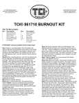
331-SV
User Manual
THREE PHASE DUPLEX
LIFT STATION CONTROL PANEL
WITH
STATIONVIEW CONTROLLER
Ashland, OH
WWW.PRIMEXCONTROLS.COM
800-363-5842
Warranty void
if panel is modified.
Call factory with
servicing questions.
This control panel must be installed and serviced by a licensed electrician in accordance with the
National Electric Code NFPA-70, state and local electrical codes.
All conduit running from the sump or tank to the control panel must be sealed with conduit sealant to prevent moisture or gases from entering the panel. NEMA 4X enclosures are for indoor or outdoor use, primarily to
provide a degree of protection against corrosion, windblown dust and rain, splashing water and hose-directed
water. Cable connectors must be liquid-tight in NEMA 4X enclosures.
Check the incoming power: voltage, amperage, and phase to meet requirements of the pump motor being
installed. Always check the pump nameplate for electrical requirements.
RED ALARM LIGHT
SEAL FAIL LIGHTS
HORN
INNER DOOR
CUTOUT IN INNER DOOR
FOR MOTOR STARTER
SILENCE
/TEST
STATION VIEW
CONTROLLER
20”
PADLOCK
HASP
H-O-A
SWITHCES
16”
PRIMEX™
2
331-SV User Manual
INSTALLATION INSTRUCTIONS
MOUNTING THE CONTROL PANEL
1. Determine mounting location for panel. If distance exceeds the length of either the level sensor cables or
the pump power cables, splicing will be required. For outdoor or wet installation, we recommend the use of a
Nema 4X junction box with liquid-tight connectors to make required connections. You must use conduit sealant to prevent moisture or gases from entering the panel. Do not mount the junction box in the wet well.
2. Determine conduit entrance locations on control panel.
3. Drill proper size holes for type of connectors being used.
NOTE: If using conduit, be sure that it is of adequate size to pull the pump and sensor cables through.
4. Attach cable connectors and/or conduit connectors to control panel.
FOR INSTALLATION WITHOUT A SPLICE, GO TO STEP 8;
FOR INSTALLATION REQUIRING A SPLICE, FOLLOW STEPS 6-7.
5. Determine location for mounting junction box according to state and local code requirements. Mount the junction box to proper support.
6. Run conduit to control panel or to junction box if required. Drill proper size holes for the type of conduit used.
Use one conduit for float switch cables and a separate one for pump cables. Do not run pump and float cables
in the same conduits.
7. Identify and label each wire before pulling through conduit into control panel and junction box. Make wire
splice connections at junction box if necessary.
CONTROL
TRANSFORMER
CURRENT TRANSDUCER
INTEGRATED MOTOR
STARTER
POWER SUPPLY
INCOMING POWER
CONTROL RELAYS
SENSORS
P1
P2
TERMINAL BLOCKS
PRIMEX™
3
331-SV User Manual
8. Firmly tighten all fittings on control panel or junction box if required.
9. In the control panel, insert the appropriate overload modules in the motor starter.
These overload modules must be ordered separately. The control panel will not operate without overload modules.
a) Adjust the dials to match motor full load amps.
b) Turn motor starter switch to the ON position.
CAUTION: Resetting the motor starter with power applied may cause the pump to run unexpectedly.
OVERLOAD MODULE
(ORDERED SEPARATELY)
LUCA05FU (1.25-5.0 FLA)
LUCA18FU (4.25-18.0 FLA
LUCA32FU (18.0-32.0 FLA)
10. Connect pump wires to terminal blocks as indicated on the provided electrical schematics.
NOTE: Three-phase motors will run in either direction. Check for proper rotation of the pump prior to final installation. To reverse the rotation, swap pump cable connections on any two terminals T1-T2-T3.
11. Connect incoming power (208/230/460 VAC, 3 phase) to the 3 position terminal block as indicated on the
provided electrical schematics. Verify that the appropriate voltage tap on the transformer primary matches
the incoming voltage.
PRIMEX™
4
331-SV User Manual
CAUTION: The transformer is wired from the factory for 460VAC. If incoming power is 230VAC or 208VAC,
the wire connections to the transformer must be changed for proper operation. Not doing so could
result in damage.
VERIFY CORRECT OPERATION OF CONTROL PANEL
AFTER INSTALLATION IS COMPLETE.
208V
230V
460V
H1
H2
H3
H4
(208) (230) (460)
X2
115V
X1
FIGURE 2 - Transformer
INSTALLATION OF LEVEL SENSORS
CAUTION: If the level sensors are not mounted correctly, the pump system will not function properly.
WARNING: Turn off all power before installing level sensors in wet well. Failure to do so could result in serious
or fatal electrical shock.
1. Use label kit to identify level sensors cables (stop, lead, lag, alarm, etc.). See control panel schematic for level
sensor connections.
2. Determine your normal operating level.
3. Mount level sensors at appropriate levels. Be sure that floats have free range of motion without touching each
other or other equipment in the basin.
4. Ensure that the level transducers cannot reach the pump.
PRIMEX™
5
331-SV User Manual
OPERATIONS - FLOAT
FLOAT SWITCH CONNECTIONS
R2
11
7
CONTROL TERMINALS
MOTOR.2
SEAL PROBE
HIGH LEVEL
AUXILIARY CONTACT
LS.1
STOP LEVEL
LS.2
LEAD ON LEVEL
LS.3
LAG ON LEVEL
LS.4
HIGH LEVEL
MOTOR.1
SEAL PROBE
MOTOR.2
THERMAL SENSOR
11 12 13 14 15 16 17 18 19 20
MOTOR.1
THERMAL SENSOR
1 2 3 4 5 6 7 8 9 10
The 331 panels are designed to operate with four floats for pump sequencing. The standard float functions are
common pump stop, lead pump start, lag pump start and alarm float.
FLOAT SWITCH OPERATION (IN AUTO MODE)
As the liquid level rises above the STOP float the pumps will remain inactive. As the level rises above the LEAD
start float, the lead pump will start and remain ON until the level drops below the STOP level. If the level continues
to rise past the start LEAD float and above the start LAG float, the second pump will start and both pumps will
remain ON until the level drops below the STOP float.
PRIMEX™
6
331-SV User Manual
FLOAT INSTALLATION
FLOAT CABLES
CONDUIT
PUMP CABLES
CONDUIT
IN-FLOW
DISCHARGE
HIGH LEVEL
LAG FLOAT
START FLOAT
STOP FLOAT
Typical float setup for a duplex lift station
WARNING:
Keep floats clear of pumps, pipes, and motor cables.
Ensure that floats cannot reach pump suction.
Do not run pump and float cables in the same conduit.
PRIMEX™
7
331-SV User Manual
OPERATIONS - TRANSDUCER
LEVEL TRANSDUCER CONNECTIONS
MOTOR 2
SEAL PROBE
HIGH LEVEL
AUXILIARY CONTACT
MOTOR 2
THERMAL SENSOR
MOTOR 1
SEAL PROBE
MOTOR 1
THERMAL SENSOR
SUBMERSIBLE
LEVEL XDCR
BACK UP
HIGH LEVEL
BACK UP
LOW LEVEL
CONTROL TERMINALS
TRANSDUCER OPERATION (IN AUTO MODE)
As the liquid level rises above the STOP set point the pumps will remain inactive. As the level
rises above the LEAD start set point, the lead pump will start and remain ON until the level drops below the STOP level. If the level continues to rise past the start LEAD and above the
start LAG start set point , the second pump will start and both pumps will remain ON until the level drops below the STOP set point.
BACK UP FLOAT (IN AUTO MODE)
If the level drops below the back up LOW LEVEL float switch, pumps will stop.
As the level rises above the LOW LEVEL Float, the pumps will remain inactive until the the level rises above the LEAD start set point.
If the level rises above the back up HIGH LEVEL float switch, both pumps will start and both pumps will remain ON until the level drops
below the back up LOW LEVEL float switch.
ALARM LEVELS
The alarm beacon and the horn will active on the following level conditions:
- If the level rises above the back up HIGH LEVEL float switch
- If the level rises above the HIGH LEVEL set point (transducer)
- If the level drops below the back up LOW LEVEL float switch
PRIMEX™
8
331-SV User Manual
TRANSDUCER INSTALLATION
SENSOR CABLES
CONDUIT
PUMP CABLES
CONDUIT
IN-FLOW
DISCHARGE
BACK UP FLOAT
HIGH LEVEL
BACK UP FLOAT
LOW LEVEL
LEVEL TRANSDUCER
WITH CABLE WEIGHT
Typical transducer (with float back up) setup for a duplex lift station
WARNING:
Keep sensors clear of pumps, pipes, and motor cables.
Ensure that floats cannot reach pump suction.
Do not run pump and float cables in the same conduit.
PRIMEX™
9
331-SV User Manual
ALARM OPERATION
The alarm will activate and remain ON only if the alarm float is tipped to the ON (close) position.
ALARM SYSTEM (HORN AND BEACON)
When an alarm condition occurs, a red light and a horn will be activated. If the silence push button is pressed,
the horn will be silenced. When the alarm condition is cleared, the alarm system is reset. The alarm system can
be tested by pressing the same push button.
HOA SWITCH
A HAND/OFF/AUTO switch is provided for each pump. In the HAND mode, the pump will run regardless of the
float switch. It will stop only if manually stopped and or an overload trip or motor thermal cutoff condition has
occurred. In the OFF position, the pumps will not RUN. In the AUTO position, the pumps will only run if the float
switches are activated in the correct sequence.
MOTOR PROTECTIVE SWITCH (MOTOR STARTER)
A motor protective switch is supplied for each pump to provide motor overload protection, branch circuit protection and a means to disconnect the pump. The overload dial on the starter must be set to match the motor Full
Load Amps (FLA).
In the event of an overload trip, the motor protective switch must be reset by first turning the selector handle
counterclockwise to the OFF position and then turning the handle clockwise to the ON position.
DRY AUXILIARY CONTACTS
Normally open - Contacts are open under normal conditions and closed when alarm condition is present. Automatically reset once alarm condition is cleared.
SEAL FAILURE CIRCUIT AND INDICATOR LIGHT
The seal fail circuit is resistance sensitive and will sense the presence of water in the pump seal chamber. When
water is sensed, the control circuit will illuminate the appropriate indicator light on the control panel. If a seal fail
occurs, turn off the pump and consult the pump manufacture for proper repair or maintenance.
THERMAL CUTOUT
The thermal cutout is wired in series with the magnetic contactor coil. If the pump’s thermal switch opens on
high temperature, the contactor will turn off and stop the pump. When the thermal switch cools and closes, the
magnetic contactor will turn on if the pump is called to run.
If the pumps are not supplied with a thermal sensor, jumper wires must be placed on the terminal block from I1 to
I2 and I5 to I6. Not doing so will result in the pumps not operating.
PRIMEX™
10
331-SV User Manual
TROUBLESHOOTING
FLOAT CONTROLS
Check the floats through their entire range of operation. Clean, adjust, or replace damaged floats.
Checking the float resistance - The float resistance can be measured to determine if the float is operating correctly or is defective. Use the following procedure to measure the float resistance:
1. Isolate the float by disconnecting one or both of the float leads from the float terminals.
2. Place one ohmmeter lead on one of the float wires, and the other ohmmeter lead on the other float wire.
3. Place the ohmmeter dial to read ohms and place on the R X 1 scale. With the float in the “off” position, the
scale should read infinity (high resistance). Replace the float if you do not get this reading. With the float in
the ON position, the scale should read nearly zero (very low resistance). Replace the float if you do not get
this reading.
NOTE: Readings may vary depending on the length of wire and accuracy of the measuring device.
FUSES
Check the continuity of the fuse. Pull the fuse out of the fuse block. With the ohmmeter on the R X 1 scale, measure resistance. A reading of infinity indicates a blown fuse and must be replaced. Replace fuse with same type,
voltage and amp rating.
TRANSFORMER
The 331 panel can be configured to operate at 208VAC, 230VAC, or 460VAC. It is factory set for 460VAC operation. Check the available incoming supply voltage to the 331 control panel prior to installation. Verify that the
connections on the transformer are correct and will match the available incoming voltage. Measure the voltage
between terminals 27 and 28 with a voltmeter. It must read 115VAC (+/- 15%) for proper operation.
PUMPS AMPS DISPLAY
If the pump amps do not display correctly check the following:
1. Check that the jumper setting on the current transducer is correct.
2. Current monitoring is enabled in the Station View™ Controller.
PRIMEX™
11
331-SV User Manual
Ashland, OH
800-363-5842
WWW.PRIMEXCONTROLS.COM
PN 1038887B
© 2013 SJE-Rhombus® Rev 01/14
PRIMEX is a trademark of SJE-Rhombus®