1
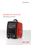
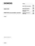
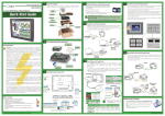
11821 Twin-O-Vac InstManIMP
1/5/06
11:52 AM
Page 1
TWIN-O-VAC
SUCTION/THERAPY UNIT
OPERATING INSTRUCTIONS
Comweld Group Pty. Ltd. ABN 56 007 226 815
71 Gower Street, Preston, Victoria, Australia 3072
Customer Service & Technical Support Line
Ph: +61-3-9474 7314, Fax: +61-3-9474 7391
In the interest of continuous improvement, COMWELD GROUP Pty. Ltd. reserves the
right to change the specifications or design of any of its products without prior notice.
The symbol, letters COMWELD GROUP MEDICAL PRODUCTS and the product names
printed in CAPITAL LETTERS are Registered Trade-marks.
Part No. Issue No.
Date
521512
301
05
11821 Twin-O-Vac InstManIMP
TA B L E
O F
1/5/06
11:52 AM
Page 3
1.0 INTRODUCTION
C O N T E N T S
These instructions are intended to provide users with
information on the features, use and care of the
Twin-O-Vac Suction/Therapy Unit.
It is important that these instructions are read and fully
understood by every intending user before any
attempt is made to use the Twin-O-Vac on a patient.
PAGE
1.0
INTRODUCTION
2
2.0
GENERAL DESCRIPTION
2
3.0
SAFETY PRECAUTIONS
3
4.0
PARTS IDENTIFICATION
3
5.0
PRINCIPLE OF OPERATION
4
6.0
OPERATIONAL CHECK
4
7.0
EQUIPMENT APPLICATION
5
8.0
CLEANING AND DISINFECTION
8
9.0
USER MAINTENANCE
8
10.0
SPECIFICATIONS
10
11.0
SERVICE RECOMMENDATIONS
11
12.0
WARRANTY
11
2.0 GENERAL DESCRIPTION
The Twin-O-Vac is a venturi actuated suction unit which
features two self sealing oxygen supply sources to
facilitate multiple therapy applications.
The Twin-O-Vac may be connected directly to an oxygen
pipeline or a cylinder regulator with a pre-set delivery
pressure. Flowmeters and other accessories should be
ordered separately.
A vacuum gauge fitted to the head of the Twin-O-Vac
indicates the vacuum generated by the unit.
Two basic models are available, one with a high suction
capability up to approximately -400 mmHg (-53 kPa)
and the other with a lower suction performance pre-set
to provide a maximum of -200 mmHg (-26 kPa).
2
11.0 SERVICING RECOMMENDATIONS
Suction Control Knob
Nylon plastic, colour coded yellow.
A Twin-O-Vac is a piece of life saving emergency
equipment. To ensure that the unit is always in a
reliable, useable condition it is recommended that the
unit be placed on a preventative maintenance
program (every 6 to 12 months depending on usage)
with your local service centre. This will provide more
detailed checks of internal components such as the
venturi and suction control valve assembly.
Oxygen Flow Performance
Minimum flow rate from oxygen outlets: 125 L/min
Bacteria Filter
A Standard Millipore brand filter, number AAWP03700 (0.8
micron) acts as a bacteria filter between the jar contents
and room air. Nominal diameter 37mm (1 7/16”).
Other Materials
Head Casting - anodised aluminium.
Suction valve - brass
Venturi - brass
Jars - High heat polyphthalate carbonate.
Handwheels - Colour coded Nylon plastic with brass insert.
Outlet Connections - Chrome plated brass.
12.0 WARRANTY
Comweld Group Pty. Ltd. warrants the purchaser that
this equipment is free from defects in material and
workmanship for a period of six years from the date of
purchase (conditions apply).
Weight
Twin-O-Vac without gauge 620g.
Twin-O-Vac with gauge 720g.
11
11821 Twin-O-Vac InstManIMP
1/5/06
11:52 AM
Page 5
10.0 SPECIFICATIONS
3.0 SAFETY PRECAUTIONS
TM117G
TM118
518632
518633
Inlet Pressure
400 kPa
50 psi
400 kPa
50 psi
Inlet Connection
SIS
DISS
SIS
DISS
Outlet Connection (Suction)
Tubing connection nominal 8mm I.D. (5/16” I.D.)
Outlet Connection (Oxygen)
SIS
DISS
SIS
DISS
Developed negative
pressure at max
setting. (mmHg)
400
min
350
min
150-200
min
150-200
min
Free air
displacement (L/min)
16
14
16
16
Gas
consumption (L/min)
22
20
22
20
4.0 PARTS IDENTIFICATION
The Twin-O-Vac should only be used if all of its parts are in
good condition.
VACUUM GAUGE
When using the Twin-O-Vac and accessory equipment,
ensure:
-
OXYGEN INLET
Handwheel
connects to oxygen
pipeline or
regulator outlet
No smoking, naked flames or sources of ignition nearby.
Use no oil or greases.
Open cylinder valve slowly and fully.
Turn off cylinder valve when not in use.
Keep cylinders cool.
Do not dump or drop cylinders.
Do not block the suction venturi outlet located at the rear
of the Twin-O-Vac. If the outlet is blocked a positive
pressure could be delivered to the patient.
Do not allow liquid in the Twin-O-Vac jar to fill past the
400 ml level.
NOTE:
SIS - Sleeve Indexed System as per AS2896
DISS - Diameter Indexed Safety System as per CGA V-5
CGA - Compressed Gas Association
GAUGE ADAPTOR
OXYGEN
OUTLET
OXYGEN OUTLET
JAR SEALING
WASHER
SUCTION INLET NIPPLE
(Patient Connection)
BACTERIA
FILTER
RECEIVER JAR
Always empty the Twin-O-Vac jar before removing the unit
from the oxygen source.
If the bacteria filter becomes wet from the liquids in the jar
the available suction pressure will be seriously restricted.
The following specifications apply to all models:-
Always fit a new bacteria filter to the Twin-O-Vac after use
with each patient.
Capacity
Receiver Jar Large - 400 ml
10
3
Figure 1
11821 Twin-O-Vac InstManIMP
1/5/06
11:52 AM
Page 7
5.0 PRINCIPLE OF OPERATION
The filter consists of two parts, a thin filter disc which is
placed against the wire mesh screen and a thicker
backing disc which is placed on top of the filter.
See Figure 2.
Suction - The oxygen source gas is controlled by a needle
valve which permits adjustable flows to be directed to a
venturi. Flow through the venturi generates a negative
pressure in the jar which is transferred via suction tubing to
a catheter or handpiece.
A bacteria filter is fitted in the Twin-O-Vac head and all
entrained air is discharged via this filter.
Oxygen Outlet - The source gas is supplied to two self
sealing outlet valves which are opened automatically by
the attachment of therapy equipment.
Oxygen flows are not controlled on the Twin-O-Vac itself
but are instead controlled via the added therapy
equipment such as a flowmeter.
Each service is independent of the other, therefore, one or
two oxygen applications can be carried out in addition to
one suction application.
WIRE MESH
HOLDING CLIP
9.1 Twin-O-Vac Accessories
9.2 User Replacement Parts
Listed below are some of the accessories suitable for use
with the Twin-O-Vac. It is recommended that if any other
accessories are intended to be used with a Twin-O-Vac
your nearest authorised distributor should be contacted
to check the compatibility of the accessory.
Listed below are the items that are considered to be user
replaceable parts. It is recommended that the user keep
stock of items such as filters, o-rings and the sealing
washer to ensure that the Twin-O-Vac is quickly
replenished after any items are used.
Description
Series-O Oxygen Regulator - Type 10 Handwheel inlet, SIS Outlet
Series-O Oxygen Regulator - Pin Index Yoke inlet, SIS Outlet
EZI-FLOW Oxygen Flowmeter - 0-15 l/min, SIS Handwheel Inlet
EZI-FLOW Oxygen Flowmeter - 0-2.5 l/min, SIS Handwheel Inlet
Flowmeter Gauge Type - 0-14 l/min, SIS Handwheel Inlet
Humidifier - 1/4” BSP female Inlet
Suction Tubing
Suction Catheter
Suction Handpiece
Item
O-ring (oxygen inlet SIS handwheel)
O-ring (gauge adaptor)
Sealing washer for jar
Receiver Jar 400 ml
Gauge Vacuum (-100kPa)
Bacteria Filter, Millipore AAWP03700 (Pack of 100)
Part No.
518800
518804
515800
515824
TM17
TM11
6.0 OPERATIONAL CHECK
Remove the Twin-O-Vac plastic jar and turn the lid upside
down.
THIN FILTER DISC &
PAPER BACKING DISC
(SHOWN TOGETHER)
COVER PLATE
Remove the domed filter cover plate by swinging the clip
to one side and check that a clean, dry bacteria filter has
been installed.
Figure 2.
4
9
Part No.
552088 (10 Pack)
515754 (Kit)
515754 (Kit)
554024
522501
554050 (100 Pack)
11821 Twin-O-Vac InstManIMP
1/5/06
11:52 AM
Page 9
8.0 CLEANING AND DISINFECTION
8.2 Ethylene Oxide
The Twin-O-Vac and its accessories must be thoroughly
cleaned after each use. When cleaning use only legally
marketed commercially available disinfectants or sterilising
agents. Disinfectants and sterilising agents must only be
used in accordance with their manufacturers instructions.
After thorough cleaning in accordance with standard
hospital procedures, the Twin-O-Vac may be
disinfected in ethylene oxide gas. After disinfection,
ensure that adequate purging and aeration is carried
out before placing the unit back into service.
The exterior of the Twin-O-Vac should be cleaned by
wiping over with a mild soap solution. Care should be
taken that none of the cleaning solution enters the gas
passages of the Twin-O-Vac.
9.0 USER MAINTENANCE
Note:
1. Inspect for cleanliness
1. For all cleaning and sterilisation procedures the vacuum
gauge and the bacteria filter must be removed. After
sterilisation, a clean, dry, bacteria filter should be fitted.
2. Check that a clean, dry filter is fitted and that filters
are being changed regularly.
At monthly intervals carry out the following checks:-
7.0 EQUIPMENT APPLICATION
Replace the filter cover over the backing disc and slide
the clip into place.
7.1 Applications
Check that the sealing washer for the plastic jar is in
place and is undamaged. Replace the plastic jar and
screw up tightly to avoid leaks.
Check the pressure gauge to ensure that the pointer
reads zero when there is no suction present.
Emergency:
- Resuscitation carts
- Portable Resuscitation kits
- In the event of a power failure, as a standby suction
unit.
Check the condition of the inlet and outlet gas specific
connectors.
Ward:
- Routine airway aspiration.
Check for any other damage that may have occurred to
the Twin-O-Vac, especially the condition of the
collection jar.
Paediatrics/Neonatal Ward:
- The adjustable suction control, in conjunction with
the suction gauge makes the Twin-O-Vac ideally
suited to infant applications.(Use low suction unit for
this application).
3. Check that inlet and outlet connections are tight.
Check that the gauge connection is tight. If loose
fittings are discovered, contact your local service
centre.
2. Always sterilise the domed metal filter cover.
3. Do not immerse the Twin-O-Vac head in any fluid.
4. The use of chemical disinfectants is not recommended.
7.2 Items Supplied with the Twin-O-Vac
-
4. Carry out the checks described in Sections 6.0 and
7.5 of this manual.
8.1 Autoclaving
The Twin-O-Vac may be autoclaved but repeated
applications may reduce the life of the product.
Remove the vacuum gauge. Autoclave temperatures must
not exceed 134˚C (280˚F).
8
5
Millipore Filter
Receiver Jar
Adaptor for Vacuum Gauge
Vacuum Gauge
Operating Instruction Manual
11821 Twin-O-Vac InstManIMP
1/5/06
11:52 AM
Page 11
7.3 Installation of Vacuum Gauge
7.5 Suction Check
7.7 Oxygen Administration
Check that the gauge adaptor rotates freely and that the oring is seated in its groove inside the base of the adaptor.
Insert the vacuum gauge into the adaptor, holding the
gauge so that the face points to the front of the Twin-OVac or the best position for viewing. Tighten the adaptor
onto the gauge by turning counterclockwise.
If connected to a cylinder regulator, ensure that the
cylinder valve is turned on and that the regulator
gauge indicates the contents. Block the end of the
metal suction inlet nipple, and slowly open the
suction control knob fully counter clockwise. Observe
that suction pressure builds up gradually and that the
gauge pointer does not stick at any position on the
dial. Check that adequate maximum suction is
generated when the control knob is fully open. (See
specifications, Section 10.0). If the suction reading is
low, recheck that the jar is tight, that the jar and
washer are in good condition and that the gauge
connection is tight.
The Twin-O-Vac provides dual
oxygen supply facilities from a single
oxygen pipeline outlet or fixed
pressure cylinder regulator.
Note: Use only finger pressure to tighten the adaptor onto
the gauge as the o-ring will seal against the gauge inlet.
Do not use tools to tighten.
To change the angle of the gauge at any time, loosen the
adaptor, turn the gauge and re-tighten the adaptor.
7.4 Connecting Twin-O-Vac to Oxygen Supply
7.6 Suction Operation
Ensure that the suction control knob is turned off fully
clockwise and connect the handwheel to an oxygen
pipeline or fixed pressure regulator. (Turn handwheel
clockwise).
Turn off the suction control clockwise and check that
there is no flow at this setting. (Listen for the hiss of
escaping oxygen at the venturi outlet). If oxygen
continues to flow contact your local service centre.
Tighten the handwheel firmly, but do not use excessive
force or any tools because the o-ring will form an effective
seal.
Attach the appropriate suction tubing and catheter or
handpiece to the suction inlet nipple. Adjust the
suction control knob counter clockwise, restrict the
suction tubing by hand, and select the desired
suction flow. The vacuum gauge will indicate the
suction level developed by the Twin-O-Vac.
6
The oxygen outlets are self sealing
fittings which will accept flowmeters
or other standard oxygen
administration equipment.
If connected to a cylinder regulator,
ensure that the cylinder valve is
turned on.
Attach a flowmeter to the self sealing
oxygen outlet.
Open the flowmeter flow control
and check that operation is
satisfactory through the full range of
flows.
Repeat this action on the second self
sealing oxygen outlet if dual
administration is required.
Twin-O-Vac fitted with two flowmeters, humidifier suction tubing and catheter
Figure 3
7