1
MIE ADR-1500
Instruction Manual
Particulate Monitor
Part Number 108836-00
31Jan2014
© 2009 Thermo Fisher Scientific Inc. All rights reserved.
Specifications, terms and pricing are subject to change. Not all products are available in all countries. Please
consult your local sales representative for details.
Thermo Fisher Scientific
Air Quality Instruments
27 Forge Parkway
Franklin, MA 02038
1-508-520-0430
www.thermo.com/aqi
WEEE Compliance
This product is required to comply with the European Union’s Waste
Electrical & Electronic Equipment (WEEE) Directive 2002/96/EC. It is
marked with the following symbol:
Thermo Fisher Scientific has contracted with one or more
recycling/disposal companies in each EU Member State, and this product
should be disposed of or recycled through them. Further information on
Thermo Fisher Scientific’s compliance with these Directives, the recyclers
in your country, and information on Thermo Fisher Scientific products
which may assist the detection of substances subject to the RoHS Directive
are available at: www.thermo.com/WEEERoHS.
Thermo Fisher Scientific
WEEE Compliance
About This Manual
This manual provides information about installing, operating, maintaining,
and servicing the Model MIE ADR-1500 Particulate Monitor. It also
contains important alerts to ensure safe operation and prevent equipment
damage. The manual is organized into the following chapters and
appendices to provide direct access to specific operation and service
information.
Chapter 1 “Introduction” provides a general description of the instrument,
and lists the specifications.
Chapter 2 “Guidelines and Instrument Layout” provides the guidelines and
layout for instrument operation.
Chapter 3 “Operation” describes the operating modes, keypad functions,
and menu-driven firmware.
Chapter 4 “Calibration and Particle Size Selection” provides the calibration
process and procedures for calibrating the instrument.
Chapter 5 “Maintenance and Service” provides step-by-step instructions for
repairing and replacing components, and a replacement parts list.
Chapter 6 “Troubleshooting” provides guidelines for diagnosing problems
or failures, and includes recommended actions for restoring operation.
Chapter 7 “Outputs and Alarm” describes serial communications and
analog/alarm output.
Chapter 8 “Optional Accessories” describes the optional equipment that
can be used with this instrument.
Appendix A “Warranty” is a copy of the warranty statement.
Appendix B “Serial Commands” provides a list of the serial port commands
that can be used to remotely control the instrument.
Safety
Thermo Fisher Scientific
Review the following safety information carefully before using the
instrument. This manual provides specific information on how to operate
the instrument, however, if the instrument is used in a manner not
specified by the manufacturer, the protection provided by the equipment
may be impaired.
MIE ADR-1500 Instruction Manual
i
About This Manual
Safety and Equipment
Damage Alerts
This manual contains important information to alert you to potential safety
hazards and risks of equipment damage. Refer to the following types of
alerts you may see in this manual.
Safety and Equipment Damage Alert Descriptions
Alert
Description
DANGER
A hazard is present that could result in death or serious
personal injury if the warning is ignored. ▲
WARNING
A hazard or an unsafe practice could result in serious
personal injury if the warning is ignored. ▲
CAUTION
A hazard or unsafe practice could result in minor to
moderate personal injury if the warning is ignored. ▲
Equipment Damage
A hazard or unsafe practice could result in property
damage if the warning is ignored. ▲
Safety and Equipment Damage Alerts in this Manual
Alert
Description
WARNING
The ADR-1500 must not be submersed. ▲
The ADR-1500 must not exceed conditions greater than
IP65. ▲
The ADR-1500 should be operated only from the type of
power sources described in this manual. ▲
Shut off ADR-1500 before replacing the internal battery,
or when plugging in or disconnecting the AC power
supply. ▲
Personal injury could occur when mounting the
instrument. Assistance may be required. ▲
The rechargeable lead acid battery must be charged in
the up-right position. ▲
Caution should be used when accessing or servicing any
exposed wiring within the instrument. ▲
Do not apply AC voltage to this connector. Maximum
allowable DC voltage is 30 V. ▲
ii
MIE ADR-1500 Instruction Manual
CAUTION
Disconnect battery power and external power supplies
before servicing. ▲
Equipment Damage
Do not attempt to lift the instrument by the cover or other
external fittings. ▲
Thermo Fisher Scientific
About This Manual
Alert
Description
Whenever the ADR-1500 is shipped, care should be taken
in repackaging it with the original factory provided
packaging. ▲
Damage could occur if not installed in a vertical, upright,
position. ▲
Damage may occur to the instrument if the environmental
conditions exceed IP65. ▲
Equipment damage may occur to instrument if power
inputs or fuse type exceeds specified ranges. ▲
Equipment damage may occur if exhaust port is blocked
or port covers are not in place if unused. ▲
Do not attach additional items to the handle for vertical
hauling as this might compromise the strength of the
handle and the ADR-1500 enclosure. ▲
It should be noted that the ADR-1500 can be powered
from any line with a voltage between 100-240 volts A.C.,
50 to 60 Hz. No internal adjustments or selections need
to be made for power lines with voltages and frequencies
in those ranges. The internal AC-to-DC power unit
performs any adjustments automatically. ▲
Please note that the important purpose of the HEPA filter
or filter cassette is to protect the pump. ▲
At no time should the ADR-1500 be running without a
filter in place, otherwise serious damage to the pump
components may result. ▲
Plugging or unplugging any external equipment (e.g.,
computer, modem, alarm circuitry, etc.) should be made
only while both the ADR-1500 and the external
equipment are shut off, in order to prevent damage or
interference due to transient electrical effects. ▲
It is recommended to turn the instrument and computer
OFF before making a connection. ▲
At no time should the ADR-1500 be running without a
filter in place, otherwise serious damage to the internal
components may result. ▲
Unless a MALFUNCTION message is displayed, or other
operational problems occur, the ADR-1500 should be
returned to the factory once every year after being placed
into service for routine check out, test, cleaning and
calibration check. ▲
Some internal components can be damaged by small
amounts of static electricity. A properly grounded
antistatic wrist strap must be worn while handling any
internal component. ▲
Thermo Fisher Scientific
Title Page
iii
About This Manual
Alert
Description
The instrument should be charged in the upright position.
▲
Replace with specified battery only. ▲
Disconnect the battery cable from the power
communication board. ▲
If unsuccessful, the instrument must be sent back to the
factory for service. ▲
For the 0 to 2 V output signal, the externally connected
load must have an impedance of more than 200 kiloohms; For the 4 to 20 mA output signal, the externally
connected load must have an impedance of less than 300
ohms. ▲
WEEE Symbol
The following symbol and description identify the WEEE marking used on
the instrument and in the associated documentation.
Symbol
Description
Marking of electrical and electronic equipment which applies to electrical and
electronic equipment falling under the Directive 2002/96/EC (WEEE) and the
equipment that has been put on the market after 13 August 2005. ▲
Where to Get Help
Service is available from exclusive distributors worldwide. Contact one of
the phone numbers below for product support and technical information
or visit us on the web at www.thermo.com/aqi.
1-866-282-0430 Toll Free
1-508-520-0430 International
iv
MIE ADR-1500 Instruction Manual
Thermo Fisher Scientific
Contents
Thermo Fisher Scientific
Chapter 1
Introduction........................................................................................................ 1-1
General Description ............................................................................ 1-3
Specifications ...................................................................................... 1-7
Chapter 2
Guidelines and Instrument Layout................................................................. 2-1
Unpacking and Parts Identification ..................................................... 2-2
Handling............................................................................................. 2-3
Safety .................................................................................................. 2-4
Positioning.......................................................................................... 2-5
Sampling Guidelines ........................................................................... 2-9
Instrument Layout ............................................................................ 2-10
Front Panel Display ....................................................................... 2-11
Bottom Power Port ........................................................................ 2-12
Side USB, Analog Panel ................................................................. 2-13
Top View ....................................................................................... 2-14
Rear View ...................................................................................... 2-15
Preparation for Operation ................................................................. 2-16
Power Options ............................................................................... 2-16
AC Power Connection ................................................................... 2-16
Installing the Inlet .......................................................................... 2-16
Electrical Connections.................................................................... 2-17
Environmental Constraints and Certifications................................... 2-18
Communications with Computer ..................................................... 2-19
Software Installation Procedure ...................................................... 2-19
Communication between ADR-1500 and Computer..................... 2-19
Chapter 3
Operation ............................................................................................................ 3-1
Operating Modes ................................................................................ 3-2
Keypad and Screen Cursor Functions and Operation.......................... 3-3
Key Press Functions ......................................................................... 3-4
Startup ............................................................................................. 3-5
Operate Menu..................................................................................... 3-6
Start A Run ...................................................................................... 3-6
Concentration/Scattering .............................................................. 3-6
Elapsed Time ................................................................................ 3-7
Maximum Run Reading................................................................ 3-7
STEL ............................................................................................ 3-7
Battery/Memory............................................................................ 3-8
Temperature/RH .......................................................................... 3-8
MIE ADR-1500 Instruction Manual
v
Contents
Flow/Pressure................................................................................ 3-8
Stop Run....................................................................................... 3-9
Delayed Start ................................................................................... 3-9
Delayed Start Edit......................................................................... 3-9
Start Time/Date............................................................................... 3-9
Start Time/Date Edit .................................................................. 3-10
Delayed Start Countdown........................................................... 3-10
Zeroing the ADR-1500.................................................................. 3-10
Zero In Progress.......................................................................... 3-11
Zero Complete............................................................................ 3-11
Logging Parameters ........................................................................ 3-11
Logging Status Edit..................................................................... 3-12
Logging Period Edit .................................................................... 3-12
Logging Site Edit ........................................................................ 3-12
Logging Tag Number.................................................................. 3-13
Battery/Memory Status .................................................................. 3-13
Configure Menu ............................................................................... 3-14
Display Average Time .................................................................... 3-14
Display Average Time Edit.......................................................... 3-14
Flow Rate....................................................................................... 3-15
Flow Rate Edit ............................................................................ 3-15
Logging Parameters ........................................................................ 3-15
Logging Status Edit..................................................................... 3-16
Logging Period Edit .................................................................... 3-16
Logging Site Edit ........................................................................ 3-16
Logging Tag Number.................................................................. 3-17
Inlet Type ...................................................................................... 3-17
Inlet Type Edit............................................................................ 3-17
RH Correction............................................................................... 3-18
RH Correction Edit .................................................................... 3-18
Alarm ............................................................................................. 3-18
Alarm Option Edit...................................................................... 3-19
Alarm Level Edit ......................................................................... 3-19
Units.............................................................................................. 3-19
Units Edit ................................................................................... 3-20
Analog Output............................................................................... 3-20
Analog Output Edit .................................................................... 3-20
LCD Backlight............................................................................... 3-21
LCD Backlight Edit .................................................................... 3-21
LCD Contrast................................................................................ 3-22
LCD Contrast Edit ..................................................................... 3-22
Time/Date ..................................................................................... 3-22
Time/Date Edit........................................................................... 3-22
Calibrate Menu ................................................................................. 3-24
Temperature Offset........................................................................ 3-24
Temperature Offset Edit ............................................................. 3-24
vi
MIE ADR-1500 Instruction Manual
Thermo Fisher Scientific
Contents
Pressure Offset ............................................................................... 3-25
Pressure Offset Edit..................................................................... 3-25
RH Offset ...................................................................................... 3-25
RH Offset Edit ........................................................................... 3-25
Flow Rate Calibration .................................................................... 3-26
Flow Rate Calibration Edit ......................................................... 3-26
Calibration Factor .......................................................................... 3-27
Calibration Factor Edit ............................................................... 3-27
Starting a Run................................................................................... 3-28
Filter Requirements........................................................................ 3-28
ZERO/Initialize Operation ............................................................ 3-28
Auto-Start (Optional) .................................................................... 3-29
Configuration Review .................................................................... 3-29
Start the Run.................................................................................. 3-32
Thermo Fisher Scientific
Chapter 4
Calibration and Particle Size Selection....................................................... 4-1
Factory Calibration ............................................................................. 4-2
How to Apply a Correction Factor...................................................... 4-3
Site Calibration Factors.................................................................... 4-4
Particle Size Cut Points ....................................................................... 4-5
Continuous Unattended Monitoring .................................................. 4-6
Chapter 5
Maintenance and Service............................................................................... 5-1
General Guidelines.............................................................................. 5-2
Replacement Parts List ........................................................................ 5-3
Instrument Storage.............................................................................. 5-6
Cleaning of Optical Sensing Chamber ................................................ 5-7
Removing the Internal Covers............................................................. 5-8
LCD Assembly Replacement............................................................. 5-10
Pump Assembly Replacement............................................................ 5-12
Communications PCB Replacement ................................................. 5-14
Optics Enclosure Assembly Removal................................................. 5-18
Heater Switch Assembly Replacement............................................... 5-20
Battery Use ....................................................................................... 5-23
Lead Acid Battery Replacement......................................................... 5-24
In-Line Flow Meter Filter with Fittings Replacement........................ 5-26
Extended Monitoring HEPA Filter Replacement .............................. 5-27
37-mm Filter Cassette Holder Assembly Replacement (Optional)..... 5-28
Bracket Assembly and Power Supply/Charger Replacement .............. 5-30
Service Locations............................................................................... 5-32
Chapter 6
Troubleshooting ................................................................................................ 6-1
Safety Precautions ............................................................................... 6-2
Troubleshooting Guide ....................................................................... 6-3
Instrument Status Flags ....................................................................... 6-5
MIE ADR-1500 Instruction Manual
vii
Contents
Error Codes in Logged Data................................................................ 6-6
Board-Level Block Diagram ................................................................ 6-7
Connector Pin Descriptions ................................................................ 6-8
Service Locations............................................................................... 6-11
viii
Chapter 7
Outputs and Alarm.............................................................................................7-1
Analog Signal Output ......................................................................... 7-2
Alarm Description and Operation....................................................... 7-3
Analog Outputs................................................................................... 7-4
Real-time RS-232 Output................................................................... 7-6
Serial Communications Protocols and Use of Modems ....................... 7-7
Chapter 8
Optional Accessories .......................................................................................8-1
37-mm Filter Cassette Holder Assembly ............................................. 8-2
Relay Kit ............................................................................................. 8-3
Alarm Relay Connection .................................................................. 8-3
Inlets ................................................................................................... 8-5
Cables ................................................................................................. 8-6
Analog Data Cable ........................................................................... 8-6
12/24 VDC Cable............................................................................ 8-6
Pole Mounting Kits............................................................................. 8-7
Appendix A
Warranty.............................................................................................................A-1
Appendix B
Serial Commands .............................................................................................B-1
MIE ADR-1500 Instruction Manual
Thermo Fisher Scientific
Figures
Figure 2–1. ADR-1500 Pole Mount..................................................................... 2-6
Figure 2–2. ADR-1500 Horizontal Tab Wall Mount ........................................... 2-7
Figure 2–3. ADR-1500 Vertical Tab Wall Mount ............................................... 2-8
Figure 2–4. ADR-1500 Front View .................................................................... 2-10
Figure 2–5. ADR-1500 Front Panel LCD Display............................................... 2-11
Figure 2–6. ADR-1500 Bottom Power Port....................................................... 2-12
Figure 2–7. ADR-1500 Side USB, Analog Panel............................................... 2-13
Figure 2–8. ADR-1500 Top View ...................................................................... 2-14
Figure 2–9. ADR-1500 Rear View..................................................................... 2-15
Figure 3–1. Keypad Overview............................................................................. 3-3
Figure 3–2. Keypad Functions............................................................................. 3-4
Figure 4–1. Cyclone D50 Curves......................................................................... 4-5
Figure 5–1. ADR-1500 Instrument Layout .......................................................... 5-5
Figure 5–2. Removing the Internal Cover........................................................... 5-9
Figure 5–3. Replacing the LCD Assembly ........................................................ 5-11
Figure 5–4. Replacing the Pump....................................................................... 5-13
Figure 5–5. Replacing the Communications PCB ............................................. 5-15
Figure 5–6. Wiring Diagram 1 .......................................................................... 5-16
Figure 5–7. Wiring Diagram 2 .......................................................................... 5-17
Figure 5–8. Replacing the Heater Switch Assembly ....................................... 5-21
Figure 5–9. Power/Com Assembly-Pump Installation ..................................... 5-22
Figure 5–10. Replacing the Lead Acid Battery................................................. 5-25
Figure 5–11. Replacing the Filters.................................................................... 5-27
Figure 5–12. Replacing the 37-mm Filter Cassette Holder Assembly............. 5-28
Figure 5–13. Filter Support and Holder – Snap Rings and Filter ..................... 5-29
Figure 5–14. Replacing the Bracket Assembly and Power Supply/Charger.... 5-31
Figure 6–1. ADR-1500 Board-Level Block Diagram ........................................... 6-7
Figure 7–1. ADR-1500 External Analog Driver................................................... 7-4
Figure 8–1. Alarm Relay Connection.................................................................. 8-3
Figure 8–2. ADR-1500 Optional Accessories ..................................................... 8-8
Thermo Fisher Scientific
MIE ADR-1500 Instruction Manual
ix
Figures
x
MIE ADR-1500 Instruction Manual
Thermo Fisher Scientific
Tables
Table 1–1. MIE ADR-1500 Specifications .......................................................... 1-7
Table 5–1. ADR-1500 Replacement Parts .......................................................... 5-3
Table 6–1. Troubleshooting – General Guide .................................................... 6-3
Table 6–2. Troubleshooting – Error Code Responses from Zeroing .................. 6-5
Table 6–3. Troubleshooting – Error Codes in Logged Data ............................... 6-6
Table 6–4. ADR-1500 Communications Board Pin Out ...................................... 6-8
Table 7–1. Analog Output Descriptions ............................................................. 7-4
Thermo Fisher Scientific
MIE ADR-1500 Instruction Manual
xi
Tables
xii
MIE ADR-1500 Instruction Manual
Thermo Fisher Scientific
Chapter 1
Introduction
The Thermo Scientific Model ADR-1500 is a real-time particulate
monitoring system designed for outdoor operation. The unit is designed for
continuous unattended monitoring with continuous real-time data
transmission to a central location and/or data logging. Its weatherproof
enclosure ensures safe and effective operation under a wide range of
ambient environmental conditions. Either a long-term monitoring HEPA
filter or optional sample collection filter can be used. Options include sharp
cut cyclones, tripod stand, relay and pole-mounting hardware.
The ADR-1500 incorporates light scattering photometry for which
Thermo Fisher Scientific (formerly MIE) is known worldwide. Long-term,
precise and drift-less measurements of airborne particulate matter
concentrations down to 1 μg/m3 are assured by a unique sate-of-the-art
combination of optical sensing and electronic processing techniques refined
over the last 25 years.
The ADR-1500 can be used for size-selective particulate measurements
using an omni-directional inlet and ACGIH traceable metal cyclones for
monitoring PM10, PM4, PM2.5, and PM1.0. For suspended particulate
monitoring the cyclone is removed from the inlet flow path and the inlet
remains in place.
In addition to the real-time particulate measurements, the instrument
provides the user with the capability to collect the sampled particles on a
37-millimeter filter for gravimetric and/or chemical analysis. Many
NIOSH filters, and thereby NIOSH methods, are compatible with the
ADR-1500.
A high-intensity flashing beacon is provided on the outside of the ADR1500 for visual alarm whenever the measured particulate concentration
exceeds a user selected alarm threshold. This alarm signal can be seen from
a considerable distance and is intended principally for perimeter
monitoring applications. For a description of the instrument and product
specifications, see the following topics:
Thermo Fisher Scientific
●
“General Description” on page 1-3
●
“Specifications” on page 1-7
MIE ADR-1500 Instruction Manual
1-1
Introduction
Thermo Fisher Scientific is pleased to supply this ambient particulate
monitoring system. We are committed to the manufacture of instruments
exhibiting high standards of quality, performance, and workmanship.
Service personnel are available for assistance with any questions or
problems that may arise in the use of this monitor. For more information
on Servicing, see Chapter 5, “Maintenance and Service”.
1-2
MIE ADR-1500 Instruction Manual
Thermo Fisher Scientific
Introduction
General
Description
The ADR-1500 is a complete particulate monitoring system designed to
provide the user with continuous measurements of the concentration of
airborne particles for suspended particulate and 50% cut-points ranging
from PM10 down to PM1, that is, the concentration of particles smaller
than 10 μm down to 1 μm aerodynamic equivalent diameter, respectively.
Reference should be made to Figure 5–1 of this manual for the location
and identification of various component elements of the ADR-1500,
described in this and subsequent sections of this manual.
The ADR-1500 samples the air through an omni-directional inlet, which
ensures representative sampling of suspended particles, even under windy
conditions. This inlet rises about 30 cm over the upper surface of the ADR1500 enclosure. The sampled air stream can then enter an optional cyclone
located downstream of the inlet, wherein particles larger than the cut-off
diameter of the cyclone are retained, and those smaller than the cut-off
diameter continue into the optical sensing stage of the monitor. The
particle cut-off size is dependent on the sampling flow rate.
After the inlet assembly, the stream enters the optical sensing stage where
the instantaneous concentration of airborne particulate matter is measured
by light scattering photometry. It is important to point out that this
sensing technique is independent of the speed with which the particles pass
through the sensing stage, and therefore changes in flow rate have no effect
on the measured concentration. However, changes in the flow rate will
affect the particle cut-point if an optional cyclone is used.
After the particle mass concentration has been sensed photometrical, the
stream passes through either a HEPA filter capsule (for long-term
monitoring) or a standard 37-mm filter holder within which a membrane
or fiber filter can be installed for further particle analysis (gravimetric,
microscopic, chemical, etc.). When using the ADR-1500 for continuous
unattended monitoring, however, it is advisable to use the HEPA capsule.
After passing through the filter stage, the filtered air stream then enters the
flow assembly. This assembly contains a rotary vane pump and a
volumetric flow rate control system based on sensing the pressure drop
across a sub-sonic orifice that is protected by an inline filter. The sampling
flow rate can be selected by keypad control on the front panel of the
instrument.
After passing through the flow assembly, the air is exhausted from the
ADR-1500 enclosure through a small bulkhead fitting. This exhaust port
can also be used as a flow return in special sampling applications where the
inlet of the ADR-1500 is connected to an environment at either positive or
negative pressure (with respect to ambient).
Thermo Fisher Scientific
MIE ADR-1500 Instruction Manual
1-3
Introduction
The ADR-1500 accepts a universal A.C. power input (100-240 VAC,
50/60 Hz) or a 12-24 D.C. power input from an auxiliary power supply.
The A.C. power is diverted to an internal 24 VDC power supply and a
dedicated charger for the internal 12-Ah rechargeable lead acid battery.
This battery is mounted at the base of the instrument and the 24 VDC
power supply and battery charger are centrally mounted above the battery.
Should the instrument be powered from an external auxiliary 12-24 VDC
power source, a dedicated cable shall be used and it must be understood
that the internal battery can not be charged from this auxiliary power
supply.
The measured concentration of particulate matter is displayed in real time
on the ADR-1500 LCD readout, provided digitally via USB and analog
voltage and current signals updated every second. In addition, the user is
provided with an alarm switching output to drive external devices (e.g.,
siren, shut-off equipment, etc.). The measured data can be logged
internally in the ADR-1500 for subsequent downloading to a PC, modem,
etc. The external USB port also serves to link to a PC for programming
internal parameters of the ADR-1500 (e.g., logging period, measurement
averaging time, alarm level, calibration constant, etc.). However, it should
be noted that an additional RS-232 digital communications is reserved as
in internal connection for most after-market wireless connections that may
be made to the instrument.
The component elements of the ADR-1500 are designed to be CE
certified, and the instrument is designed for IP65.
The ADR-1500 borrows the highly sensitive nephelometric (i.e.,
photometric) monitor from the pDR-1500 whose legacy light scattering
sensing configuration has been optimized for the measurement of the
respirable fraction of airborne dust, smoke, fumes and mists in industrial
and other indoor and outdoor environments. The ADR-1500 incorporates
a temperature and relative humidity (RH) sensor to mitigate the positive
bias with elevated ambient RH. Additionally, the flow control is truly
volumetric and is maintained through digital feedback of the onboard
barometric pressure sensor, temperature sensor, and calibrated differential
pressure across a precision orifice.
Downstream of the internal vacuum pump is a HEPA filter which will
ensure a clean air source is delivered to the calibrated orifice and exhausted
from the instrument. Zeroing is accomplished by attaching a HEPA filter
to the inlet for a few minutes. By providing filtered air through the optical
bench, the optical background of the instrument is established throughout
the dynamic range of the instrument.
The ADR-1500 is a compact, rugged and totally self-contained instrument
designed for rapid deployment and unattended operation mounted on a
1-4
MIE ADR-1500 Instruction Manual
Thermo Fisher Scientific
Introduction
wall, post, or tripod. It is powered either by its internal rechargeable
battery, or by an AC supply or auxiliary power source.
The ADR-1500 covers a wide measurement range: from 0.001 mg/m3 (1
μg/m3) to 400 mg/m3, a 400,000-fold span, corresponding to very clean air
up to an extremely high aerosol concentration.
In addition to the auto-ranging real-time concentration readout, the ADR1500 offers the user a wide range of information by scrolling its two-line
LCD screen, such as run start time and date, time averaged concentration,
elapsed run time, maximum and STEL values with times of occurrence,
battery voltage, remaining data storage memory, temperature, RH,
volumetric flow rate, barometric pressure, etc.
Operating parameters selected, diagnostic information, and calibration
displays are also available with the ADR-1500. From the instrument
display panel the user can:
●
Enable a run
●
Enable an auto-start run time and date
●
Zero the instrument
●
Fully configure data logging options
●
Adjust display average time
●
Adjust analog span output
●
Identify type of inlet/cyclone installed
●
Adjust flow rate with automatic D50 cut point feedback
●
Enable/disable f (RH) correction
●
Enable/disable the heater
●
Enable/disable and select alarm output threshold
●
Adjust time and date
●
Enable/disable display backlight and contrast
●
Calibrate barometric pressure, temperature, RH, flow rate, and dust
response factor
Furthermore, the ADR-1500 features complete, large capacity internal data
logging capabilities with retrieval through an externally connected
computer via USB device. The stored information (> 450k data points)
includes average concentration and maximum values with time information
and tag numbers, operating parameters, error codes, and each timestamped logged record provided concentration, temperature, RH,
barometric pressure, and error status.
Thermo Fisher Scientific
MIE ADR-1500 Instruction Manual
1-5
Introduction
Selectable alarm levels with built-in audible signal and switched output, a
USB communications port, and a programmable analog concentration
output (voltage and current) are all part of this versatile instrument.
A custom software package (pDR Port) is provided with the ADR-1500 to
program operating/logging parameters (e.g., logging period, alarm level,
concentration display averaging time, etc.) as well as to download stored or
real-time data to a PC or laptop for tabular and/or graphic presentation. If
required, the data can also be imported to standard spreadsheet packages
(e.g., Microsoft Excel™, Lotus 1-2-3™, etc.).
The ADR-1500 combines, easy to use menu-driven software, and advanced
diagnostics to offer unsurpassed flexibility and reliability. The ADR-1500
specifications follow.
1-6
MIE ADR-1500 Instruction Manual
Thermo Fisher Scientific
Introduction
Specifications
Table 1–1 lists the specifications for the Model ADR-1500.
Table 1–1. MIE ADR-1500 Specifications
Thermo Fisher Scientific
Concentration measurement range
(auto-ranging)1
0.001 to 400 mg/m3
Scattering coefficient range
1.1 x 10⁻⁶ to 0.6 m-1 (approx.) @ λ = 880 nm
Precision/repeatability over 30
days (2-sigma2 with heater off and
RH-correction disabled)
±2% of reading or ± 0.005 mg/m3, whichever is larger,
for 1-second averaging time
±0.5% of reading or ± 0.0015 mg/m3, whichever is
larger, for 10-second averaging time
±0.2% of reading or ± 0.0005 mg/m3, whichever is
larger, for 60-second averaging time
Accuracy1
±5% of reading (± precision) traceable to SAE Fine test
dust
Resolution
0.1 μg/m3
Particle size range of maximum
response
0.1 to 10 μm
Flow rate range
1.0 to 3.5 liters/min
Aerodynamic particle cut-point
range
1.0 to 10 μm, with optional cyclone accessories
Concentration display updating
interval
1 second
Concentration display averaging
time3
1 to 60 seconds
Alarm level adjustment range3
0.01 to 400 mg/m3
Alarm averaging time3
Real-time (1 to 60 seconds), or STEL (15 minutes)
Data logging averaging periods3
1 second to 1 hour
Total number of data points that
can be logged in memory
> 450,000
Number of data tags (data sets)
100 (0–99)
Logged data
Record no., concentration or scattering data,
temperature, relative humidity, barometric pressure,
data flags, time and date
Run summary
Model number, software version, serial no., tag
number, start time, start date, logging period, cal factor,
units of measure, RH correction setting, max. conc.,
time of max. conc., max. STEL, time of max. STEL, avg.
conc., alarm on/off, alarm threshold, error codes, inlet
setting, flow rate setting and site name
MIE ADR-1500 Instruction Manual
1-7
Introduction
1-8
MIE ADR-1500 Instruction Manual
Elapsed time range
0 to 100 hours (resets to 0 after 100 hours)
Time keeping and data retention
> 10 years
Readout display
LCD 16 characters (4 mm height) x 2 lines
Serial interface
High Speed USB/RS-232 (RS-232 is reserved for
wireless applications), 19,200 baud
Computer requirements
IBM-PC compatible, 486 or higher, Windows™ ’95 or
higher, > 8 MB memory, > 10 MB hard disk drive, CD
Drive, VGA or higher resolution monitor
Real-time digital signal (1 sec-1)
Concentration, flow, temperature, relative humidity,
barometric pressure, time, date
Real-time analog signal1
0 to 2 V and 4 to 20 mA, with selectable full scale
ranges between 0.1 and 400 mg/m3
0 - 0.1, 0 - 0.4, 0 - 1.0, 0 - 4.0, 0 - 10, 0 - 40, 0 - 100, and
0 - 400, mg/m3
Minimum load impedance for voltage output: 200 kΩ
Maximum load impedance for current output: 300 Ω
(when powered by AC power supply)
Alarm output
Load impedance > 100 kΩ
Alarm ON = short to ground
Alarm OFF = open
Internal battery run time
1.2 L/min (heater and alarm off) > 100-hour run-time
1.2 L/min (heater and alarm constantly on > 24-hour
run-time
3.5 L/min (heater and alarm constantly on > 12-hour
run-time
Internal battery charge time4
95% charge capacity 7.3 hours (@100-250 VAC 50/60
Hz)
100% charge capacity 14 hours (@100-250 VAC 50/60
Hz)
AC source
100-240 VAC 50-60 Hz
12/24 VDC for solar or auxiliary battery options
Fuses
1.5 amp, slow blow fuse, 5 x 20 mm
Operating environment
-10 to 50 °C (14 to 122 °F), 10 to 95% RH, noncondensing
Storage environment:
-20 to 70 °C (-4 to 158 °F)
Dimensions)
21 in (533 mm) H x 17 in (431 mm) W x 17 in (215 mm D
Weight
28.5 lbs. (12.9 kg)
Optional Cyclones
GK 2.05 (Red) primarily for PM4 thru PM10
SCC 1.062 (Blue) primarily for PM1 thru PM4
Thermo Fisher Scientific
Introduction
Integrated Sample Filter holder
(Optional)
Millipore type MAWP 037 AO (with 0.8 μm pore size
filter)
Whatman type 1827 037 (with 1.5 μm pore size filter)
NIOSH Methods 0500 and 0600 use Millipore type
PVC5 037 00 (with 5 μm pore size filter) and a GK 2.05
Cyclone
Service Filter
Small integrated HEPA filter for flow meter protection
Large integrated HEPA filter for long-term monitoring
applications
Notes:
1
Referred to gravimetric calibration with SAE Fine (ISO Fine) test dust (mmd = 2 to 3 μm, g = 2.5, as
aerosolized)
Thermo Fisher Scientific
2
At constant temperature and full battery voltage
3
User selectable
4
Internal battery will not charge when using 12-24 VDC external auxiliary power supply
MIE ADR-1500 Instruction Manual
1-9
Chapter 2
Guidelines and Instrument Layout
This chapter includes unpacking and parts identification, positioning and
handling of the instrument, monitoring applications, instrument layout,
outdoor provisions, and computer requirements.
Thermo Fisher Scientific
●
“Unpacking and Parts Identification” on page 2-2
●
“Handling” on page 2-3
●
“Safety” on page 2-4
●
“Positioning” on page 2-5
●
“Sampling Guidelines” on page 2-9
●
“Instrument Layout” on page 2-10
●
“Preparation for Operation” on page 2-16
●
“Environmental Constraints and Certifications” on page 2-18
●
“Communications with Computer” on page 2-19
MIE ADR-1500 Instruction Manual
2-1
Guidelines and Instrument Layout
Unpacking and
Parts
Identification
Carefully unpack the ADR-1500 from the shipping container. The ADR1500 is provided to the user with the following standard accessories:
●
Power cord (110 or 220)
●
Wall-mounting hardware
●
USB communications cable
●
pDR Port software CD ROM
●
Particulate inlet
●
Zeroing filter
●
Instruction manual
If any parts are missing, contact Thermo Fisher Scientific immediately.
Equipment Damage Do not attempt to lift the instrument by the cover or
other external fittings. ▲
Note Do not discard the packaging material. ▲
2-2
MIE ADR-1500 Instruction Manual
Thermo Fisher Scientific
Guidelines and Instrument Layout
Handling
The ADR-1500 is a sophisticated optical/electronic instrument and should
be handled accordingly. Although the ADR-1500 is very rugged, it should
not be subjected to excessive shock, vibration, temperature or humidity
outside the stated specifications.
WARNING The ADR-1500 must not be submersed. ▲
WARNING The ADR-1500 must not exceed conditions greater than
IP65. ▲
If the ADR-1500 has been exposed to low temperatures (e.g., in the trunk
of a car during winter) for more than a few minutes, care should be taken
to allow the instrument to return near room ambient temperature before
operation. This is advisable because water vapor may condense on the
interior surfaces of the ADR-1500 causing temporary malfunction or
erroneous readings. Once the instrument warms up to temperature, such
condensation will have evaporated. Re-zeroing is recommended upon
installation.
Equipment Damage Whenever the ADR-1500 is shipped, care should be
taken in repackaging it with the original factory provided packaging. ▲
Thermo Fisher Scientific
MIE ADR-1500 Instruction Manual
2-3
Guidelines and Instrument Layout
Safety
Review the following information carefully:
●
Read and understand all instructions in this manual.
●
Do not attempt to disassemble the instrument. If maintenance is
required, return unit to the factory for qualified service or contact
technical support.
WARNING The ADR-1500 should be operated only from the type of
power sources described in this manual. ▲
●
When installing or replacing the battery, follow the instructions
provided within this manual.
●
Shut off ADR-1500 and any external devices (e.g., PC) before
connecting or disconnecting them.
WARNING Shut off ADR-1500 before replacing the internal battery, or
when plugging in or disconnecting the AC power supply. ▲
2-4
MIE ADR-1500 Instruction Manual
Thermo Fisher Scientific
Guidelines and Instrument Layout
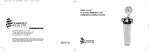
Positioning
The ADR-1500 real-time aerosol monitor can be operated in a vertical
(upright) position and preferred for outdoor fixed location operation as
well as for most indoor applications.
The ADR-1500 can be pole mounted (Figure 2–1) or wall (or post)
mounted using the four wall mounting tabs that protrude above and below
the enclosure. These tabs have mounting holes with a diameter of 5/16 (7.9
mm). If required, these mounting tabs can be removed. For details, see
Figure 2–2 and Figure 2–3. For more information on the optional 2-inch,
3-inch, and 4-inch pole mounting kits, see chapter 8 “Optional
Accessories”.
When mounting the ADR-1500 care should be taken to ensure that the
front door of the unit can be opened without hindrance, and that free
access is provided to the connectors and feed-throughs on the right face of
the enclosure.
It is important to ensure free access of the air to be monitored to the
sampling inlet. For ambient air monitoring, the omni-directional inlet
provided with the ADR-1500 should always be used, and this inlet should
not be obstructed by nearby objects, in order to ensure representative
sampling.
Under typical operating conditions, the door of the ADR-1500 enclosure
should be closed. Holes are provided on the enclosure to add a padlock to
prevent unauthorized access to the interior of the unit. The door should be
opened only to access the control keys of the ADR-1500, to replace either
of the filters, or for other maintenance.
WARNING Personal injury could occur when mounting the instrument.
Assistance may be required. ▲
Equipment Damage Damage could occur if not installed in a vertical,
upright, position. ▲
Thermo Fisher Scientific
MIE ADR-1500 Instruction Manual
2-5
Guidelines and Instrument Layout
Pole Clamps (4)
1/4-20 x 1.25
Phillips Hex Head (2)
Rails (2)
1/4” Washer (4)
1/4-20 x 1.20
Pan Head Screw (4)
Figure 2–1. ADR-1500 Pole Mount
WARNING The rechargeable lead acid battery must be charged in the upright position. ▲
2-6
MIE ADR-1500 Instruction Manual
Thermo Fisher Scientific
Guidelines and Instrument Layout
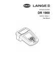
Figure 2–2. ADR-1500 Horizontal Tab Wall Mount
WARNING The rechargeable lead acid battery must be charged in the upright position. ▲
Thermo Fisher Scientific
MIE ADR-1500 Instruction Manual
2-7
Guidelines and Instrument Layout
Figure 2–3. ADR-1500 Vertical Tab Wall Mount
WARNING The rechargeable lead acid battery must be charged in the upright position. ▲
2-8
MIE ADR-1500 Instruction Manual
Thermo Fisher Scientific
Guidelines and Instrument Layout
Sampling
Guidelines
For ambient air sampling, the omni-directional inlet unit must be used to
minimize wind speed and direction effects on particle sampling
representativeness. This special omni-directional inlet is provided as a
standard accessory of the ADR-1500. On receipt by the customer, this inlet
will arrive packaged separately, and needs to be installed. Refer to Figure 2–
7 for the final (installed) appearance of the omni-directional inlet. To
install proceed as follows:
Slide the omni-directional inlet onto the inlet stem of the ADR-1500 until
it bottoms. To remove the omni-directional inlet, lift and twist the unit
from the inlet stem.
If the ADR-1500 is to be used for extractive sampling (e.g., from a
chamber, duct, stack, etc.) a flexible plastic tubing (preferably electrically
conductive) can be used and connected to the inlet stem on the upper face
of the ADR-1500. In this case the omni-directional inlet is not used and a
3/8-inch compression fitting with Teflon or nylon ferrules should be used.
For sampling situations involving water sprays, fog, etc. it is recommended
that the in-line inlet heater be switched on. This optional operational
configuration ensures the sample relative humidity will not exceed 70%. If
not necessary, and to extend the run-time of the ADR-1500, when running
off of the internal battery, simply switch the internal heater off.
Equipment Damage Damage may occur to the instrument if the
environmental conditions exceed IP65. ▲
Thermo Fisher Scientific
MIE ADR-1500 Instruction Manual
2-9
Guidelines and Instrument Layout
Instrument
Layout
The user should become familiar with the location and function of all
externally accessible controls, connectors and other features of the ADR1500. Refer to Figure 2–4 and Figure 5–1. All related functions are
externally accessible.
Qualified Thermo Fisher Scientific personnel should perform all repair and
maintenance. Please contact the factory if any problem should arise. Do
not attempt to disassemble the ADR-1500, except as described in Chapter
5, “Maintenance and Service”, otherwise voiding of instrument warranty
will result.
WARNING Caution should be used when accessing or servicing any
exposed wiring within the instrument. ▲
Figure 2–4. ADR-1500 Front View
2-10
MIE ADR-1500 Instruction Manual
Thermo Fisher Scientific
Guidelines and Instrument Layout
Front Panel Display
The front panel contains the five touch switches (keys) and the LCD screen
required for the operation of the ADR-1500. The touch keys provide
tactile ("popping") feedback when properly actuated. For more information
on keys, see “Key Press Functions” on page 3-4
The two-line, 16-character per line LCD indicates either measured values
of concentration (instantaneous and time averaged on the same screen),
elapsed run time, maximum and short term excursion limit (STEL) values,
operating and logging parameters, diagnostics, command prompting or
other messages.
The LCD screen is backlit whenever the ADR-1500 is selected as an always
on feature.
Refer to Figure 2–5 for location of controls and display below.
RH Control
Heater Switch
ON/OFF
Display and Keypad
Figure 2–5. ADR-1500 Front Panel LCD Display
Thermo Fisher Scientific
MIE ADR-1500 Instruction Manual
2-11
Guidelines and Instrument Layout
Bottom Power Port
There are three critical components to the bottom panel of the ADR-1500;
the universal AC power port (100-240 VAC 50/60 Hz), the auxiliary 1224 VDC power port, and the instrument exhaust. The AC power should be
connected whenever the internal batteries are exhausted or not present,
and/or when running continuously from the AC line. Any other DC source
(e.g., solar power supply, external battery, etc.) to be used to power the
ADR-1500 would be connected to its respective port. Please note that the
auxiliary 12-24 VDC will not charge the internal battery.
Refer to Figure 2–6 below for the location of power port items on the
bottom of the ADR-1500.
Equipment Damage Equipment damage may occur to instrument if power
inputs or fuse type exceeds specified ranges. ▲
Equipment Damage Equipment damage may occur if exhaust port is
blocked or port covers are not in place if unused. ▲
Fuse Drawer
Exhaust
12-24 VDC Input
100-240 AC Input
50/60 Hz
Figure 2–6. ADR-1500 Bottom Power Port
2-12
MIE ADR-1500 Instruction Manual
Thermo Fisher Scientific
Guidelines and Instrument Layout
Side USB, Analog
Panel
There are four features of the right side of the ADR-1500 enclosure; the
locking latches for the hinged door, the sealed USB connection, the sealed
analog/alarm connect and a sealed cord grip. The locking latches join the
enclosure body to the front door and compress the gasketing for proper
sealing of the enclosure. These latches also permit the use of padlocks, if
necessary. The sealed USB connector is used for PC-based communication
for instrument configuration, data downloads and firmware upgrade using
the factory-supplied pDR Port user interface. The sealed analog/alarm
connector is for tying the ADR-1500 to an external data logger or PLC
using the factory-supplied cable. The cord grip permits the user with access
to the interior instrument for customization (e.g., wireless
communications) and to the optional relay connector. For more
information on options, see Chapter 8, “Optional Accessories”.
Refer to Figure 2–7 below for the location of items on the Side USB,
Analog Panel of the ADR-1500.
Equipment Damage Equipment damage may occur if exhaust port is
blocked or port covers are not in place if unused. ▲
Omni-Directional Inlet
Beacon
USB Connector
Analog/Alarm Connector
Sealed Cord Grip
USB Cover
Figure 2–7. ADR-1500 Side USB, Analog Panel
Thermo Fisher Scientific
MIE ADR-1500 Instruction Manual
2-13
Guidelines and Instrument Layout
Top View
There are three features on the top of the ADR-1500; the inlet stem, the
beacon, and the carry handle. The inlet stem is used to draw the sample
into the nephelometric stage for aerosol sensing. This stem is 3/8-inch
O.D. and is compatible with 3/8 compression fittings. It is recommended
that the compression ferrules be made of nylon or Teflon; otherwise,
compressed steel ferrules may render the instrument useless for backward
compatibility with the intended inlet accessories. The connections to this
stem are:
●
Omni-directional inlet
●
Cyclone adapter
●
Zeroing filter
●
3/8-inch compression fitting with nylon or Teflon ferrules
The yellow beacon will flash if the alarm is enabled and the measured
concentration exceeds the threshold chosen by the user. The alarm may be
enabled for either an instantaneous value or for a STEL concentration.
The carry handle is to be used for carrying the instrument or hauling the
instrument to an elevated installation. The carry handle is designed for the
weight of the ADR-1500 only.
Equipment Damage Do not attach additional items to the handle for
vertical hauling as this might compromise the strength of the handle and
the ADR-1500 enclosure. ▲
Refer to Figure 2–8 below for the location of items on the inlet stem, the
beacon, and carry handle of the ADR-1500.
Inlet
Beacon
Carry Handle
Figure 2–8. ADR-1500 Top View
2-14
MIE ADR-1500 Instruction Manual
Thermo Fisher Scientific
Guidelines and Instrument Layout
Rear View
The rear of the ADR-1500 shows four brass threaded bosses that can be
used with the wall mounting kit (standard accessory). Furthermore, a polemounting kit (optional accessory) may be attached to the rear of the
enclosure in a 2-inch, 3-inch, or 4-inch pole. Tripod mounting conversion
kits are also available. For more information on mounting options, see
Chapter 8, “Optional Accessories”.
Refer to Figure 2–9 below for the location of the four brass threaded
bosses.
Brass Threaded
Bosses (4)
Figure 2–9. ADR-1500 Rear View
Thermo Fisher Scientific
MIE ADR-1500 Instruction Manual
2-15
Guidelines and Instrument Layout
Preparation for
Operation
Power Options
To begin using the ADR-1500, the user must first verify that either the
AC/DC power supply is connected to both the instrument and suitable
wall socket, or the instrument is installed with a charged battery.
The ADR-1500 has three basic power options:
●
AC Power Supply (100-240 VAC 50/60 Hz)
●
Auxiliary DC Power Supply (12-24 VDC)
●
Battery Power (12 VDC 12 Ah lead acid)
An A.C. power cord (US or EU) is provided as a standard accessory with
the ADR-1500 and is to be used with the universal A.C. power supply
receptacle.
AC Power
Connection
The ADR-1500 as received from the factory is provided with an A.C.
power cord and US or EU three-prong plug. The user can therefore
connect the ADR-1500, as received, into an A.C. outlet to operate the
system.
Equipment Damage It should be noted that the ADR-1500 can be
powered from any line with a voltage between 100-240 volts A.C., 50 to 60
Hz. No internal adjustments or selections need to be made for power lines
with voltages and frequencies in those ranges. The internal AC-to-DC
power unit performs any adjustments automatically. ▲
Installing the Inlet
Prior to starting a measurement run, it is recommended that the ADR1500 is zeroed. This can be achieved by placing a HEPA filter onto the
inlet stem and following the “Zeroing the ADR-1500” procedure on page
3-10. Do not attempt to zero through a cyclone.
The next step is to install a clean inlet assembly onto the inlet system. If a
particle size cut-point is needed, an optional cyclone can be installed
between the inlet stem and the omni-directional inlet.
If tubing is to be used, attach the tubing to the inlet stem or the cyclone
stem.
The ADR-1500 is shipped from the factory with a high-capacity HEPA
filter immediately downstream of the optical assembly. This permits
periods of time. For sample recovery, it is recommended to use the optional
37-mm filter cassette holder, which can accommodate glass filter, Teflon,
MCE and PVC filter material.
2-16
MIE ADR-1500 Instruction Manual
Thermo Fisher Scientific
Guidelines and Instrument Layout
Equipment Damage Please note that the important purpose of the HEPA
filter or filter cassette is to protect the pump. ▲
Equipment Damage At no time should the ADR-1500 be running without
a filter in place, otherwise serious damage to the pump components may
result. ▲
Electrical
Connections
If AC power is not available and the ADR-1500 must operate outside the
instrument specifications for the internal battery, please consult with
Thermo Fisher Scientific for a Technical Note regarding the use of an
external battery or other DC source.
Equipment Damage Plugging or unplugging any external equipment (e.g.,
computer, modem, alarm circuitry, etc.) should be made only while both
the ADR-1500 and the external equipment are shut off, in order to prevent
damage or interference due to transient electrical effects. ▲
Thermo Fisher Scientific
MIE ADR-1500 Instruction Manual
2-17
Guidelines and Instrument Layout
Environmental
Constraints and
Certifications
The ADR-1500 is designed to be reasonably dust and splash resistant; it is
weatherproof.
The pDR-1500 is certified for compliance with the electromagnetic
radiation limits for a Class B digital device, pursuant to part 15 of the FCC
Rules. The unit also complies and is marked with the CE (European
Community) approval for both immunity to electromagnetic radiation and
absence of excessive emission interference.
The unit also complies with:
2-18
MIE ADR-1500 Instruction Manual
●
ANSI/UL 61010-1:2004, 2nd Edition, Safety Requirements for
Electrical Equipment for Measurement, Control and Laboratory
Use – Part 1: General Requirements
●
CAN/CSA C22.2 No. 61010-1:2004 2nd Edition, Safety Requirements
for Electrical Equipment for Measurement, Control and Laboratory
Use – Part 1: General Requirements
●
CENELEC EN 61326-1
●
FCC 47 CFR 15B cIA
Thermo Fisher Scientific
Guidelines and Instrument Layout
Communications
with Computer
The computer requirements to install and run the software provided with
the ADR-1500 (pDR Port) is the following:
●
IBM-PC compatible
●
Pentium I or higher processor
●
Minimum operating system: Windows 95 and later
●
32 MB of RAM
●
10 MB hard disk drive
●
CD-ROM
●
VGA or higher resolution monitor
Thermo Fisher Scientific custom hardware and software provided with
ADR-1500 as standard accessories:
Software
Installation
Procedure
Communication
between ADR-1500
and Computer
●
USB communications cable
●
Software CD (pDR Port)
To install the Thermo Scientific provided software (pDR Port) in the
computer, proceed as follows:
●
Insert the CD labeled pDR Port into the computer
●
The install program should start automatically
●
The computer displayed install shield then serves to guide the rest of
the installation.
●
Please be sure to accept the Silicon Laboratories USB Driver
installation.
To effect the communication between the ADR-1500 (via the pDR Port
software installed in the computer) and the PC, proceed as follows:
Equipment Damage It is recommended to turn the instrument and
computer OFF before making a connection. ▲
Thermo Fisher Scientific
●
Connect the ADR-1500 to one of the computer’s USB ports using the
USB communication cable
●
Key ON the ADR-1500; hold ON/OFF for 4 seconds
●
From your computer Start menu, or your computer desktop, open the
pDR Port software program. A multi-tabbed notebook display should
MIE ADR-1500 Instruction Manual
2-19
Guidelines and Instrument Layout
appear on the computer screen. From the menu bar or the embedded
Settings window, the serial connection port can be selected (e.g., COM
4). Select the port to which the USB cable has connected to on you
computer using the Select Port pop-up window and click OK to
proceed. The user may now click on the Show Instrument Panel to
emulate the instrument keypad or utilize the tabs within the pDR Port
notebook display.
Most operations with the pDR Port software program are self-evidently
labeled, including fly-over dialog boxes. In addition, instructions may be
found in the On-line Help files by selecting Help and then Contents.
The following operating/logging parameters of the ADR-1500 can be
selected (edited) via the computer:
2-20
MIE ADR-1500 Instruction Manual
●
Current date (year, month and day of the month)
●
Current time (hour, minute and second)
●
Display averaging time (1 to 60 seconds, in 1-second increments)
●
Calibration factor (0.01 to 9.99, in 0.01 increments)
●
Analog output full scale concentration (0.1, 0.4, 1, 4, 10, 40, 100, or
400 mg/m3
●
Analog output status (enabled or disabled)
●
Alarm level (0.01 to 400.0 mg/m3, in 1-μg/m3 increments)
●
Alarm status (enabled or disabled)
●
Humidity correction (enabled or disabled)
Thermo Fisher Scientific
Guidelines and Instrument Layout
The serial number of the ADR-1500 is transferred automatically to the PC
and displayed on the screen. From the multi-tabbed notebook, select from
the following options:
Main. This tab allows the user to select the serial port connection,
and show or hide the instrument panel.
Data text. This tab allows the user to download, tabulate, print and
delete data, or transfer to a CSV file of the data downloaded from
the ADR-1500. First – click on the blue instrument icon (
) in
the upper left hand corner of this Data text Tab and the “Select a
Tag number” window will appear. From this window, the user can
select a single Tag (data file) to be loaded or deleted. In the image
below, the “Delete all data” box appears with a check mark. By
selecting this box and clicking on Delete, all tag files can be deleted
at once.
Thermo Fisher Scientific
MIE ADR-1500 Instruction Manual
2-21
Guidelines and Instrument Layout
In this second image of the Data Text tab, it shows a Tag File
loaded to the window. The data can now be viewed in the Data
Graph tab and saved as a CSV file.
2-22
MIE ADR-1500 Instruction Manual
Thermo Fisher Scientific
Guidelines and Instrument Layout
Data graph. This tab automatically plots the data from the Data
text tab into a time series plot. Mass concentration or scattering
coefficient, temperature, relative humidity and barometer pressure
can all be plotted on this graph simultaneously or independently.
Configure instrument. This screen allows the user to edit the
instrument configuration. Click on the item to be edited and select
or type in the new value. To review the parameter values currently
programmed into the ADR-1500, click on Get current
configuration. After editing the parameters, click on Set new
configuration to input the newly selected values into the ADR1500.
Thermo Fisher Scientific
MIE ADR-1500 Instruction Manual
2-23
Guidelines and Instrument Layout
Site List. This tab allows the user to retrieve, edit, and set the site
list for the instrument. Site lists may also be read and written to a
file on a computer.
2-24
MIE ADR-1500 Instruction Manual
Thermo Fisher Scientific
Chapter 3
Operation
This chapter describes the operating modes, keypad and screen cursor
functions, menu-driven firmware, and starting a run. For details, see the
following topics:
Thermo Fisher Scientific
●
“Operating Modes” on page 3-2
●
“Keypad and Screen Cursor Functions and Operation” on page 3-3
●
“Operate Menu” on page 3-6
●
“Configure Menu” on page 3-14
●
“Calibrate Menu” on page 3-24
●
“Starting a Run” on page 3-28
MIE ADR-1500 Instruction Manual
3-1
Operation
Operating Modes
The ADR-1500 has five modes of Operation:
1. Start-up. This is accomplished by holding the ON/OFF key for 4
seconds whereby the splash screen will appear.
2. Run Mode. This is when the instrument is measuring aerosol and
operating with an active flow rate. Normally the instrument is set for
data logging to be enabled in this mode.
3. Standby. This is when the instrument is in an idle mode during which
the user is interfacing with the instrument menu, configuring the
instrument, downloading data, calibration, or when the instrument is
set to begin sampling via an auto-start.
4. Zeroing. This mode is used to establish the optical background
(Rayleigh scattering) of the ADR-1500. During this mode of operation
the user is required to install a zeroing tube that connects the inlet stem
to a HEPA filter.
5. Shutdown. Accomplished by holding the ON/OFF key until text on
screen is no longer visible. The instrument is off.
3-2
MIE ADR-1500 Instruction Manual
Thermo Fisher Scientific
Operation
Keypad and Screen
Cursor Functions
and Operation
Before starting the ADR-1500, it is recommended that the user become
familiar with the keypad functionality. There are three menus that outline
the keypad functions and these are OPERATE, CONFIGURE, and
CALIBRATE. Figure 3–1 below demonstrates the ADR-1500 menu
structure. Following is a description of each menu.
Thermo Scientific
ADR-1500 v1.30
Operate
Configure
Calibrate
Start a Run
Concentration/Scattering
Elapsed Time
Maximum Run Reading
STEL
Battery/Memory
Temperature/RH
Flow/Pressure
Stop Run
Delayed Start
Delayed Start Edit
Start Time/Date
Start Time/date Edit
Delayed Start Countdown
Zero
Zero in Progress
Zero Complete
Logging Parameters
Logging Status Edit
Logging Period Edit
Logging Site Edit
Logging Tag Number
Battery/Memory Status
Display Average Time
Display Average Time Edit
Flow Rate
Flow Rate Edit
Logging Parameters
Logging Status Edit
Logging Period Edit
Logging Site Edit
Logging Tag Number
Inlet Type
Inlet Type Edit
RH Correction
RH Correction Edit
Alarm
Alarm Option Edit
Alarm Level Edit
Units
Units Edit
Analog Output
Analog Output Edit
LCD Backlight
LCD Backlight Edit
LCD Contrast
LCD Contrast Edit
Time/Date
Time/Date Edit
Temperature Offset
Temperature Offset Edit
Pressure Offset
Pressure Offset Edit
RH Offset
RH Offset Edit
Flow Rate Calibration
Flow Rate Calibration Edit
Calibration Factor
Calibration Factor Edit
Figure 3–1. Keypad Overview
Thermo Fisher Scientific
MIE ADR-1500 Instruction Manual
3-3
Operation
The Figure 3–2 below depicts the Operate Menu screen of the ADR-1500
after start-up and identifies the specific keys on the keypad.
ON/OFF Key
Escape Key
UP Arrow Key
DOWN Arrow Key
ENTER Key
Figure 3–2. Keypad Functions
The equivalent of this screen is represented below, and this format will be
used throughout the remainder of this Instruction Manual.
ON
OPERATE
OFF
ESC UP DOWN ENTER
Key Press Functions
The following is a general description of the key press functions:
●
ON/OFF powers the instrument on or off. Press and hold ON/OFF
for at least 4 seconds.
●
ESC selects the display through which the current display was accessed
(back up a level) or to bail out of an edit display without saving and
return to the previous display from which the current display was
assessed.
●
3-4
MIE ADR-1500 Instruction Manual
UP ( ▲ ) scrolls through menu displays that are in a circular list (in a
backward direction) or scrolls through values (also in a backward
direction) in a display that is not part of a list (an edit display).
Thermo Fisher Scientific
Operation
●
●
DOWN ( ▼ ) scrolls through menu displays that are in a circular list
(in a forward direction) or scrolls through values (also in forward
direction) in a display that is not part of a list (an edit display).
ENTER selects the function displayed on menu displays that are in a
circular list, or used to exit and save the values as displayed in an edit
display and return to the previous display from which the current
display were accessed.
Note Holding down the ▲ or ▼ key will cause the rightmost digit to
increase or decrease twice per second. After 5 seconds the next digit to the
left will increase or decrease. Releasing the button returns control to the
rightmost digit again. ▲
Startup
To place the ADR-1500 into the Startup mode, press and hold the
ON/OFF key for 4 seconds until you hear a beep followed by the Splash
Screen appearing with the backlight on. The following splash screen
appears:
ThermoScientific
ADR-1500 v01.30
This screen appears for three seconds upon initiation of a power-up
sequence, then default directly to the Operate Menu screen. In this screen
you may scroll up or down to the Calibrate Menu or Configure Menu,
respectively.
Thermo Fisher Scientific
MIE ADR-1500 Instruction Manual
3-5
Operation
Operate Menu
The Operate Menu is used to access the list of displays allowing the user to
access the operating modes and run-time parameters of the ADR-1500
including “Start A Run”, “Delayed Start”, “Zero”, “Logging Parameters”
and “Battery/Memory Status”.
OPERATE
Start A Run
The Start A Run menu allows the user to begin monitoring/sampling. The
run will be logged only if the asterisk (*) appears at the end of the first
display line (see below). If the ADR-1500 is ready to begin a monitoring
run, press ENTER and the instrument will begin operating as configured.
Equipment Damage Verify that the exhaust port and the inlet port are not
blocked. ▲
●
●
From the Operate Menu, press the ENTER key and scroll the ▲ or ▼
key to the Start a Run screen.
Press the ENTER key and the instrument will begin operating as
configured.
START A RUN
*
Once a run is started, press the ▲ and ▼ keys to view a series of the
following displays.
Concentration/Scattering
3-6
MIE ADR-1500 Instruction Manual
The instrument measures concentration or scattering coefficient of ug/m3
for concentration or 1/Mm for scattering coefficient. The real-time
concentration is presented on the first line and the time-weighted average is
presented on the second line. The real-time concentration is an average
taken over a time interval called “Display Time”, which is programmed by
the user. The presence of the asterisk (*) in the first line indicates that data
logging is enabled.
Thermo Fisher Scientific
Operation
●
Elapsed Time
From the Start a Run screen, press the ENTER key and scroll the ▲ or
▼ key to the Conc/Scat screen or press the ESC key to stop a run.
CONC
32.3*μg/m3
TWA
34.0 μg/m3
The Elapsed Time screen allows the user to view the elapsed time in hours,
minutes and seconds on the first line and the start time and date of the run
on the second line. After ten seconds of key pad inactivity, the display will
return to the concentration/scattering screen.
●
From the Start a Run screen, press the ENTER key and scroll the ▲ or
▼ key to the ET screen or press the ESC key to stop a run.
ET 00000:07:12
08:15 13-Nov-09
Maximum Run Reading
The MAX display screen allows the user to view maximum real-time
reading (concentration or scattering coefficient) of the run and the time of
occurrence. After ten seconds of key pad inactivity, the display will return
to the concentration/scattering screen.
●
From the Start a Run screen, press the ENTER key and scroll the ▲ or
▼ key to the Max screen or press the ESC key to stop a run.
MAX
56.4 ug/m3
08:26 13 Nov-09
STEL
The STEL screen allows the user to view STEL maximum reading
concentration or scattering coefficient. The STEL is based on the average
of the last 15 minutes prior to the time of occurrence. After ten seconds of
key pad inactivity, the display will return to the concentration/scattering
screen.
●
Thermo Fisher Scientific
From the Start a Run screen, press the ENTER key and scroll the ▲ or
▼ key to the Stel screen or press the ESC key to stop a run.
MIE ADR-1500 Instruction Manual
3-7
Operation
STEL 34.1 ug/m3
08:30 13-Nov-09
Battery/Memory
The Battery/Memory screen reads the battery voltage and the percentage of
data logging memory left. After ten seconds of key pad inactivity, the
display will return to the concentration/scattering screen.
●
From the Start a Run screen, press the ENTER key and scroll the ▲ or
▼ key to the Battery/Memory screen or press the ESC key to stop a
run.
BATTERY
12.6V
MEMORY LEFT
97%
Temperature/RH
The Temperature/RH screen allows the user to view the current ambient
temperature (degrees Celsius) and relative humidity. After ten seconds of
key pad inactivity, the display will return to the concentration/scattering
screen.
●
From the Start a Run screen, press the ENTER key and scroll the ▲ or
▼ key to the Temp/RH screen or press the ESC key to stop a run.
TEMP
RHUM
Flow/Pressure
The Flow/Pressure screen allows the user to view the flow rate in liters per
minute and the (ambient) atmospheric pressure in millimetres mercury.
After ten seconds of key pad inactivity, the display will return to the
concentration/scattering screen.
●
From the Start a Run screen, press the ENTER key and scroll the ▲ or
▼ key to the Flow/Pres screen or press the ESC key to stop a run.
FLOW
PRES
3-8
MIE ADR-1500 Instruction Manual
27.1 C
41.4%
2.000 LPM
750 mmHg
Thermo Fisher Scientific
Operation
Stop Run
The Stop Run screen offers the user to confirm that the run is to be
stopped.
●
●
From the Start a Run screen, press the ENTER key and scroll the ▲ or
▼ key to the Stop Run screen or press the ESC key to stop a run.
Press the Enter key and the run is terminated.
STOP RUN?
PRESS ENTER
Delayed Start
The Delayed Start screen offers the user to view and edit the delayed start
status as “enabled” or “disabled”.
●
From the Operate menu, press the ENTER key and scroll the ▲ or ▼
key to the Delayed Start screen.
DELAYED START
DISABLED
Delayed Start Edit
The Delayed Start Edit screen allows the user to edit the delayed start as
“enabled” or “disabled”. The asterisk (*) appears to the left of the field
being edited.
●
From the Delayed Start screen, press the ENTER key to enable or
disable a delayed start.
DELAYED START
* ENABLED
Start Time/Date
The Start Time/Date screen allows the user to view and edit the delayed
start time and date. The instrument will store the start time and date
regardless of whether Delayed Start is enabled or disabled. If the start time
and date is earlier than the current time, then it defaults to the current
time.
●
Thermo Fisher Scientific
From the Operate menu, press the ENTER key and scroll the ▲ or ▼
key to the Start@ screen.
MIE ADR-1500 Instruction Manual
3-9
Operation
START@
Start Time/Date Edit
14:45:30
13-Nov-09
The Start Time/Date Edit screen allows the user to edit the delayed start
time and date. In the display, the ENTER and the ESC keys provide
navigation through six fields within the display in the following sequence:
hours, minutes, seconds, years, months, and days. The ENTER key
navigates forward while the Esc key navigates backwards. The ▲ and ▼
keys are used to increment/decrement the field values. The asterisk (*)
appears to the left of the field being edited.
●
From the Start@ screen, press the ENTER key and to advance to edit the
next field, except if day (of month) is selected: the delayed start time
and date saved, the delayed start status is enabled, and the display
advances to Delayed Start Countdown.
START@ *14:45:30
13-Nov-09
Delayed Start Countdown
The Delayed Start Countdown screen displays the time of day that the
ADR-1500 will start a run on the first line and the amount of time
remaining before the instrument starts this run in days, hours, minutes,
and seconds. The presence of the asterisk in the first line indicates that data
logging is enabled.
START@ *14:45:30
120Days hh:mm:ss
Zeroing the ADR-1500
The Zero Instrument screen is used to initiate a zero sequence to measure
and store the optical background. The second line displays advice to the
user that a filter must be applied to the Total Inlet to provide clean
(particulate-free) air to the optics for this process.
●
From the Operate menu, press the ENTER key and scroll the ▲ or ▼
key to the Zero Instrument screen.
Note Do not zero through the red or blue sharp-cut cyclones. Only zero
through a clean Total Inlet. ▲
3-10
MIE ADR-1500 Instruction Manual
Thermo Fisher Scientific
Operation
ZERO INSTRUMENT
FILTER READY
Zero In Progress
The Zeroing screen is shown while the ADR-1500 is performing a
background measurement and optical signal offset adjustment, and key
functions are different.
●
From the Zero Instrument screen, press the ENTER key and the display
advances to Zero in Progress (Zeroing).
ZEROING
PLEASE WAIT
Note Please be sure a HEPA filter is installed to a clean Total Inlet during
this procedure to ensure proper measurements. Do not zero through the
cyclones. ▲
Zero Complete
After zeroing is complete, if the measurement was successful and within
specification, the following screen appears. If the measurement was
successful and outside of specification the instrument will respond with
“COMPLETE: BKG HI”. If diagnostics indicated that measurement was
compromised, the instrument will respond with “FAILURE 0x00ee”,
where 0x00ee is a hex code indicating the type of error the diagnostic
failure encountered during background measurement. Re-zero the
instrument. After three attempts, contact customer service.
ZERO INSTRUMENT
COMPLETE: BKG OK
Logging Parameters
The Logging Parameters display screen indicates on the first line whether
data logging is enabled or disabled. The second line of this screen displays
the logging period for 3 seconds, displays site label for 3 seconds, and tag
number for 3 seconds in sequence.
●
Thermo Fisher Scientific
From the Operate menu, press the ENTER key and scroll the ▲ or ▼
key to the Logging screen.
MIE ADR-1500 Instruction Manual
3-11
Operation
LOGGING ENABLED
1:00:00 h:m:s
LOGGING ENABLED
Factory default
LOGGING ENABLED
01
Logging Status Edit
The Logging Status Edit screen allows the user to enable or disable data
logging. The asterisk (*) appears to the left of the field being edited.
●
From the Logging Parameters screen, press the ENTER key and the
display advances to Logging Period Edit.
●
Press the ENTER key enable or disable data logging.
LOGGING STATUS
*
ENABLED
Logging Period Edit
The Logging Period Edit screen allows the user to the logging period. The
asterisk (*) appears to the left of the field being edited. The ▲ and ▼ keys
are used to increment/decrement the time. If either button is held, then the
logging period will change twice per second but the editing focus will
switch to the digit on the left after the button is held for five seconds.
●
From the Logging Parameters screen, press the ENTER key and the
display advances to Logging Period Edit.
●
Press the ENTER key to enable or disable data logging.
LOGGING PERIOD
* 14:45:30 h:m:s
Logging Site Edit
3-12
MIE ADR-1500 Instruction Manual
The Logging Site Edit screen allows the user to select from the list of 50
logging sites. Each site has three associated values: Site Number, a Site
Name, and a Calibration Factor. The Site Name is the only value displayed
Thermo Fisher Scientific
Operation
on the second line. Pressing the ▲ and ▼ keys changes the Site Number
and the corresponding Site Name appears on the second line. Also, the
corresponding Calibration Factor is chosen. The Site Numbers are in range
(1, 2, 3..., 50), the Site Names and Calibration Factors are editable only by
external serial command. The asterisk (*) appears to the left of the field
being edited.
●
From the Logging Parameters screen, press the ENTER key and the
display advances to Logging Period Edit.
●
Press the ENTER key to save Site selection and forward to Logging Tag
Number.
LOGGING SITE
*Site 01
Logging Tag Number
The Logging Tag Number screen allows the user to select the tag no. (00,
01, 02...99), a number assigned to a logged run as label to access/retrieve
the stored data. The asterisk (*) appears to the left of the field being edited.
●
From the Logging Parameters screen, press the ENTER key and the
display advances to Logging Period Edit.
●
Press the ENTER key to save Site selection and forward to Logging Tag
Number.
LOGGING TAG NO.
*
00
Battery/Memory
Status
The Battery/Memory Status screen reads the internal battery voltage on the
first line and the percentage of the un-written memory on the second.
●
From the Operate menu, press the ENTER key and scroll the ▲ or ▼
key to the Battery/Memory screen.
BATTERY
12.6V
MEMORY LEFT
97%
Thermo Fisher Scientific
MIE ADR-1500 Instruction Manual
3-13
Operation
Configure Menu
The Configure Menu is used to access the list of displays allowing the user
to configure how the instrument measures and logs data including “Display
Avg Time”, “Flow Rate”, “Logging Parameters”, “Inlet Type”, “RH
Correction”, “Alarm”, “Units”, “Analog Output”, “LCD Backlight”, LCD
Contrast” and “Time/Date”.
CONFIGURE
Display Average
Time
The Display Average Time screen offers the user to adjust the running
(boxcar) average time of the displayed concentration (or scattering
coefficient) between 1 and 60 seconds. The average concentration displayed
is the value scaled to the analog output and offered as an alarm criterion.
●
From the Configure menu, press the ENTER key and scroll the ▲ or ▼
key to the Display Avg Time screen.
DISPLAY AVG TIME
10 seconds
Display Average Time
Edit
The Display Average Time Edit screen allows the user to change the
running average displayed on the screen between 1 and 60 seconds. This
also doubles as the running average that is provided as an analog output
and also as one of the values that triggers the alarm. Use the ▲ and ▼ keys
to increase or decrease the display average time by seconds. The asterisk (*)
appears to the left of the field being edited.
●
From the Display Avg Time screen, press the ENTER key and edit the
display averaging time.
●
Press the ENTER key to save the display averaging time and return to
Display Avg Time screen.
DISPLAY AVG TIME
*
11 seconds
3-14
MIE ADR-1500 Instruction Manual
Thermo Fisher Scientific
Operation
Flow Rate
The Flow Rate screen displays the set flow rate and the corresponding
cyclone mass median diameter 50% cut point (D50).
●
From the Configure menu, press the ENTER key and scroll the ▲ or ▼
key to the Flow Rate screen.
FLOW RATE
1.19 LPM
Flow Rate Edit
The Flow Rate Edit screen allows the user to edit the volumetric flow rate.
The flow range is 1–3.5 L/min and if a cyclone has already been chosen,
the corresponding 50% aerodynamic cut point (D50 in micrometers) will
change simultaneously. Use the ▲ and ▼ keys to increase or decrease the
flow rate in increments of 0.01 LPM. The asterisk (*) appears to the left of
the field being edited.
●
From the Flow Rate screen, press the ENTER key and edit the flow rate.
●
Press the ENTER key to save the flow rate and return to the Flow Rate
screen.
FLOW RATE
*1.19 LPM
Logging Parameters
(D50)
10.00
(D50)
10.00
The Logging Parameters display screen indicates on the first line whether
data logging is enabled or disabled. The second line of this screen displays
the logging period for 3 seconds, the site label for 3 seconds, and the tag
number for 3 seconds in sequence.
●
From the Configure menu, press the ENTER key and scroll the ▲ or ▼
key to the Logging screen.
LOGGING ENABLED
1:00:00 h:m:s
LOGGING ENABLED
Factory default
Thermo Fisher Scientific
MIE ADR-1500 Instruction Manual
3-15
Operation
LOGGING ENABLED
01
Logging Status Edit
The Logging Status Edit screen allows the user to enable or disable data
logging. The asterisk (*) appears to the left of the field being edited.
●
From the Logging Parameters screen, press the ENTER key and edit the
logging status.
●
Press the ENTER key to save the logging status and forward to the
Logging Period edit.
LOGGING STATUS
*
ENABLED
Logging Period Edit
The Logging Period Edit screen allows the user to edit the logging period.
The asterisk (*) appears to the left of the field being edited. Use the ▲ and
▼ keys to increment or decrement the time. If either button is held, then
the logging period will change twice per second but the editing focus will
switch to the digit on the left after the button is held for five seconds.
●
From the Logging status screen, press the ENTER key to edit the
logging period.
●
Press the ENTER key to save the logging period and forward to the
Logging Site edit.
LOGGING PERIOD
*
1:00:00 h:m:s
Logging Site Edit
3-16
MIE ADR-1500 Instruction Manual
The Logging Site Edit screen allows the user to select from the list of 50
logging sites. Each site has three associated values: Site Number, a Site
Name, and a Calibration Factor. The site name is the only value displayed
on the second line. Use the ▲ and ▼ keys to change the site number and
the corresponding site name appears on the second line. Also, the
corresponding calibration factor is chosen. The site numbers are in range
(1, 2, 3..., 50), the site names and calibration factors are editable only by
external serial command. The asterisk (*) appears to the left of the field
being edited.
Thermo Fisher Scientific
Operation
●
From the Logging Period screen, press the ENTER key to edit the
logging site.
●
Press the ENTER key to save the logging period and forward to the
Logging Site edit.
LOGGING SITE
*Site 01
Logging Tag Number
The Logging Tag Number screen allows the user to select the tag no. (00,
01, 02...99), a number assigned to a logged run as label to access/retrieve
the stored data. The asterisk (*) appears to the left of the field being edited.
●
From the Logging Site screen, press the ENTER key to edit the logging
tag number.
●
Press the ENTER key to save Site selection and return to the Logging
Parameters display screens.
LOGGING TAG NO.
*
00
Inlet Type
The Inlet Type screen allows the user to select the inlet type being used
(Red, Cyclone, or Total).
●
From the Configure menu, press the ENTER key and scroll the ▲ or ▼
key to the Inlet Type screen.
INLET TYPE
BLUE CYCLONE
Inlet Type Edit
Thermo Fisher Scientific
The Inlet Type Edit screen allows the user to select the type of inlet being
used. Inlet types are: Cyclone, Blue Cyclone or Total Inlet. Use the ▲ and
▼ keys to change the inlet type. The asterisk (*) appears to the left of the
field being edited.
●
From the Inlet Type screen, press the ENTER key to edit the inlet type.
●
Press the ENTER key to save the inlet type and return to the Inlet Type
screen.
MIE ADR-1500 Instruction Manual
3-17
Operation
INLET TYPE
*RED CYCLONE
RH Correction
The RH Correction screen allows the user to view whether RH correction
is enabled or disabled.
●
From the Configure menu, press the ENTER key and scroll the ▲ or ▼
key to the RH Correction screen.
RH CORRECTION
DISABLED
Note RH Correction should be enabled when the RH is expected to
exceed 50–60%. Ambient monitoring should always use the RH
Correction as being enabled. However, precision can be affected between
collocated devices. ▲
RH Correction Edit
The RH Correction Edit screen allows the user to enable or disable RH
correction. The asterisk (*) appears to the left of the field being edited
●
From the RH Correction screen, press the ENTER key to edit the RH
correction.
●
Press the ENTER key to save the RH correction and return to the RH
Correction screen.
RH CORRECTION
* ENABLED
Alarm
3-18
MIE ADR-1500 Instruction Manual
The Alarm screen indicates the alarm options for triggering the alarm
(Disabled, Instant, or STEL) and the value at which it is triggered. The
instant setting causes the alarm to be triggered when the displayed
concentration is higher than the instant alarm level setting. The STEL
setting causes the alarm to be triggered when the 15 minute rolling
(boxcar) average is higher than the STEL alarm level setting. Each of the
two enabled alarm options use separately stored alarm level values.
Thermo Fisher Scientific
Operation
Note The units mg/m3 are replaced with /km when the ADR-1500 is
measuring scattering coefficient, using the units 1/Mm. ▲
●
From the Configure menu, press the ENTER key and scroll the ▲ or ▼
key to the Alarm screen.
ALARM
INSTANT
0.15 mg/m3
Alarm Option Edit
The Alarm Option Edit screen allows the user to edit the alarm. Alarm
options are: Instant, STEL, or Disabled. Use the ▲ and ▼ keys to change
the alarm option. The asterisk (*) appears to the left of the field being
edited.
●
From the Alarm screen, press the ENTER key and edit the alarm option.
●
Press the ENTER key to save the alarm option and forward to the Alarm
Level edit screen.
ALARM
INSTANT
*
STEL
Alarm Level Edit
The Alarm Level Edit screen allows the user to edit the alarm for which the
alarm is triggered. Use the ▲ and ▼ keys to increase or decrease the alarm
level by 0.001 mg/m3. The asterisk (*) appears to the left of the field being
edited.
●
From the Logging status screen, press the ENTER key to edit the alarm
level.
●
Press the ENTER key to save the alarm option and return to the Alarm
screen.
ALARM
STEL
*
200.00 mg/m3
Units
Thermo Fisher Scientific
The Units screen allows the selection of units from micrograms per cubic
meter (μg/m3) or to a measure of the aerosol scattering coefficient in units
of inverse mega meters (1/Mm).
MIE ADR-1500 Instruction Manual
3-19
Operation
Note When the units /Mm are chosen, the RH correction becomes
automatically disabled. ▲
●
From the Configure menu, press the ENTER key and scroll the ▲ or ▼
key to the Units edit screen.
UNITS
Units Edit
1/Mm
The Units Edit screen allows the user to change the option for units. Use
the ▲ and ▼ keys to toggle between the two unit options. The asterisk (*)
appears to the left of the field being edited.
●
From the Units screen, press the ENTER key to edit the units.
●
Press the ENTER key to save the units and return to the Units screen.
UNITS
1/Mm
* ug/m3
Analog Output
The Analog Output screen indicates the status of the analog output
(enabled/disabled) and offers the user the option to enable or disable the
analog output and change the analog span range in corresponding units of
measure (ug/m3 or 1/Mm). The proportional voltage output range is 0–2
VDC for the analog output.
●
From the Configure menu, press the ENTER key and scroll the ▲ or ▼
key to the Analog Output screen.
ANALOG OUTPUT
ENABLED
Analog Output Edit
3-20
MIE ADR-1500 Instruction Manual
The Units Edit screen allows the user to configure the analog output. The
values offered for selection are compatible with the selected units. The
values offered for /Mm (scattering coefficient) are: disabled, 10/Mm,
100/Mm, 1000/Mm, 10000/Mm, and 100000/Mm. The values offered for
μg/M3 (concentration) are: disabled, 0.10 mg/m3, 0.40 mg/m3, 1.00
mg/m3, 4.00 mg/m3, 10.0 mg/m3, 40 mg/m3, 100 mg/m3, 400 mg/m3, and
Thermo Fisher Scientific
Operation
1000 mg/m3. Use the ▲ and ▼ keys to cycle through the list of analog
output items. The asterisk (*) appears to the left of the field being edited.
●
From the Analog Output screen, press the ENTER key to edit the
analog output.
●
Press the ENTER key to save the analog output selection and return to
the Analog Output screen.
ANALOG OUTPUT
* 0.40 mg/m3
LCD Backlight
The LCD Backlight screen displays whether the backlight is enabled or
disabled and offers the user to choose whether to enable or disable the LCD
backlight. If the backlight is enabled and the instrument is running solely
from battery power, the backlight will come on for a period of 10 seconds
after each keystroke. Thereafter, the backlight will automatically shut off in
an effort to conserve power. If running on external power supply, the LCD
backlight stays on.
●
From the Configure menu, press the ENTER key and scroll the ▲ or ▼
key to the LCD Backlight screen.
LCD BACKLIGHT
DISABLED
LCD Backlight Edit
The LCD Backlight Edit screen allows the user to enable or disable the
LCD backlight. Use the ▲ and ▼ keys to toggle between enable or
disable. The asterisk (*) appears to the left of the field being edited.
●
From the LCD Backlight screen, press the ENTER key to edit the LCD
backlight.
●
Press the ENTER key to save the LCD backlight status and return to the
LCD Backlight screen.
LCD BACKLIGHT
* ENABLED
Thermo Fisher Scientific
MIE ADR-1500 Instruction Manual
3-21
Operation
LCD Contrast
The LCD Contrast screen allows the user to view and edit the contrast of
the display. Lower settings darken the contrast and make the display more
readable at colder temperatures. Higher settings lighten the contrast and
make the display more readable at warmer temperatures. The nominal
setting is 25.
●
From the Configure menu, press the ENTER key and scroll the ▲ or ▼
key to the LCD Contrast screen.
LCD CONTRAST
25
LCD Contrast Edit
The LCD Contrast Edit screen allows the user to edit the contrast of the
display. Use the ▲ and ▼ keys to increment or decrement the LCD
contrast. The asterisk (*) appears to the left of the field being edited.
●
From the LCD Contrast screen, press the ENTER key to edit the LCD
contrast.
●
Press the ENTER key to save the LCD contrast status and return to the
LCD Contrast screen.
LCD CONTRAST
* 20
Time/Date
The Time/Date screen displays the current time and date and offers the
user to re-program the time and date.
●
From the Configure menu, press the ENTER key and scroll the ▲ or ▼
key to the Time/Date screen.
TIME
Time/Date Edit
3-22
MIE ADR-1500 Instruction Manual
15:59:41
13-Nov-09
The Time/Date Edit screen allows the user to edit the current time and
date. The Start Time/Date Edit screen allows the user to edit the delayed
start time and date. In the display, the ENTER and the ESC keys provide
Thermo Fisher Scientific
Operation
navigation through six fields within the display in the following sequence:
hours, minutes, seconds, years, months, and days. The ENTER key
navigates forward while the Esc key navigates backwards. The ▲ and ▼
keys are used to increment/decrement the field values. The asterisk (*)
appears to the left of the field being edited.
●
From the Time/Date screen, press the ENTER key to and to advance to
edit the next field.
●
Press the ENTER key to save the time/date and return to the Time/Date
screen.
TIME
Thermo Fisher Scientific
*15:59:41
13-Nov-09
MIE ADR-1500 Instruction Manual
3-23
Operation
Calibrate Menu
The Calibrate Menu is used to access the list of displays allowing the user
to calibrate the sensors used to measure scattering, temperature, relative
humidity, barometric pressure, flow rate, and the time and date. The
displays include “Temp Offset”, “Pressure Offset”, “RH Offset”, “Flow
Rate Cal”, and “Cal Factor”.
CALIBRATE
Temperature Offset
The Temperature Offset screen allows the user to view and edit the
temperature offset of the measurement to coincide with their traceable
standards.
●
From the Calibrate Menu, press the ENTER key and scroll the ▲ or ▼
key to the Temp Offset screen.
TEMP OFFSET
0.0
22.3 C
Temperature Offset Edit
The Temperature Offset Edit screen allows the user to edit the temperature
offset. Use the ▲ and ▼ keys to increase or decrease the user temperature
offset in increments of 0.1 in degrees Celsius. The asterisk (*) appears to
the left of the field being edited.
●
From the Temp Offset screen, press the ENTER key and edit the
temperature offset.
●
Press the ENTER key to save the temperature offset and return to Temp
Offset screen.
TEMP OFFSET
* 0.1
22.2 C
Please note that a precise and accurate calibration of the RH-sensor is
critical to maintaining precision between collocated devices when using RH
Correction enabled.
3-24
MIE ADR-1500 Instruction Manual
Thermo Fisher Scientific
Operation
Pressure Offset
The Pressure Offset screen allows the user to view and edit the pressure
offset of the barometric pressure measurement to coincide with their
traceable standards.
●
From the Calibrate Menu, press the ENTER key and scroll the ▲ or ▼
key to the Pressure Offset screen.
PRESSURE OFFSET
0
760 mmHg
Pressure Offset Edit
The Pressure Offset Edit screen allows the user to edit the pressure offset.
Use the ▲ and ▼ keys to increase or decrease the user pressure offset in
increments of 1 in millimetres of mercury. The asterisk (*) appears to the
left of the field being edited.
●
From the Pressure Offset screen, press the ENTER key and edit the
pressure offset.
●
Press the ENTER key to save the user pressure offset and return to
Pressure Offset screen.
PRESSURE OFFSET
*
10
750 mmHg
RH Offset
The RH Offset screen allows the user to view and edit the RH offset of the
barometric pressure measurement to coincide with their traceable
standards.
●
From the Calibrate Menu, press the ENTER key and scroll the ▲ or ▼
key to the RH Offset screen.
RH OFFSET
0.0
47.3 %
RH Offset Edit
Thermo Fisher Scientific
The RH Offset Edit screen allows the user to edit the RH offset. Use the
▲ and ▼ keys to increase or decrease the RH offset in increments of 0.1%
RH. The asterisk (*) appears to the left of the field being edited.
MIE ADR-1500 Instruction Manual
3-25
Operation
●
From the RH Offset screen, press the ENTER key and edit the RH
offset.
●
Press the ENTER key to save the user RH offset and return to the RH
Offset screen.
RH OFFSET
* 5.0
42.3 %
Flow Rate
Calibration
The Flow Rate Calibration screen allows the user the option to perform a
multi-point inlet flow calibration.
●
From the Calibrate Menu, press the ENTER key and scroll the ▲ or ▼
key to the Flow Rate Cal screen.
FLOW RATE CAL
Flow Rate Calibration
Edit
The Flow Rate Calibration Edit screen allows the user to calibrate the six
flow control settings and define the flow rate at each flow control setting.
This will build a table of the six calibration point to be used for
interpolating the flow control setting to achieve the flow rate set in the
Configure menu’s “Flow Rate Edit”.
The flow rate calibration is accomplished in a sequence of six displays for
six flow calibration points, setting the six flow control settings for the
corresponding six defined flow rate setting. The ENTER and ESC keys are
used to navigate through the edit fields, while the ▲ and ▼ keys are used
to increase and decrease the values. The asterisk (*) appears to the left of the
field being edited.
For factory settings, the flow control adjust is adjusted for flow calibration
points (1, 2, 3, 4, 5, and 6) to produce corresponding defined flow rates
(1.00, 1.50, 2.00, 2.50, 3.00, and 3.50 liters per minute) and the defined
flow rates are kept at the factory default setting. The user may, however,
redefine the defined flow rate for each flow calibration point to get a more
accurate calibration. However, the defined flow rate values must increase in
value as the flow calibration point increases.
In the following screen there are two values shown; ADJ = 188 and LPM =
1.00. In this screen the 188 is the pump speed control value used to achieve
1.00 L/min. The user may adjust the motor speed to achieve 1.00 L/min or
3-26
MIE ADR-1500 Instruction Manual
Thermo Fisher Scientific
Operation
may adjust the measured inlet flow rate that is equal at that pump speed.
After pressing the ENTER key, the next calibration point is pursued.
Note Should the temperature and pressure be re-calibrated, the accuracy of
the flow calibration should be verified. ▲
●
From the Flow Rate Cal screen, press the ENTER key to navigate
forward, until last step (flow calibration point 6, defined flow rate) the
display returns to the Flow Rate Cal screen and the new calibration is
saved only if at least one of the values was edited.
FLOW RATE CAL 1
ADJ* 188LPM:1.00
Calibration Factor
The Calibration Factor screen shows the site number selected and allows
the user to edit the calibration factor for that site number. The calibration
factor is the value used to scale the concentration output to agree with a
primary calibration or user defined standard.
In the following screen, the ADR-1500 shows the instrument is operating
for Site 1, and the Calibration Factor is 1.000 which will provide a 1:1
response with the factory calibration. For more information about
calibration, see Chapter 4, “Calibration and Particle Size Selection”.
●
From the Calibrate Menu, press the ENTER key and scroll the ▲ or ▼
key to the Cal Factor screen.
CAL FACTOR
1.000
Calibration Factor Edit
The Calibration Factor Edit screen allows the user to edit the calibration
factor values. Use the ▲ and ▼ keys to increase or decrease the value by
0.001. The asterisk (*) appears to the left of the field being edited.
●
From the Cal Factor screen, press the ENTER key and edit the values.
●
Press the ENTER key to save the calibration factor associated with the
site number and return to Cal Factor screen.
CAL FACTOR
*
1.000
Thermo Fisher Scientific
1
2
MIE ADR-1500 Instruction Manual
3-27
Operation
Starting a Run
Filter Requirements
The following provides a brief overview of how to start a monitoring and
sampling run.
Before starting a run, a HEPA filter or optional 37-mm filter must be
inserted downstream of the optical assembly. The recommended 37-mm
filters are glass microfibre filters. If using the 5-micron PVC filters, use the
glass microfibre filters as a backing media when using battery power.
Equipment Damage At no time should the ADR-1500 be running without
a filter in place, otherwise serious damage to the internal components may
result. ▲
ZERO/Initialize
Operation
Before initiating a measurement run it is advisable to perform the zeroing
and automatic internal check out sequences, to ensure optimal operation.
●
From the Operate menu, press the ENTER key and scroll the ▲ or ▼
key to the Zero Instrument screen.
ZERO INSTRUMENT
FILTER READY
Attach a HEPA filter to the Total Inlet and press ENTER. Do not zero
through the cyclone.
During zeroing, each range within the auto-ranging potential is used to
measure the optical background of the instrument and each value is stored
for subsequent data calculations. The duration of a Zero Operation is
usually 2-3 minutes. After Zeroing is complete, the following screen should
be present:
ZERO INSTRUMENT
COMPLETE: BKG OK
●
3-28
MIE ADR-1500 Instruction Manual
From the Zero Instrument screen, by pressing the ▼ key, the user
proceeds to a series of logging screens in the following order:
Thermo Fisher Scientific
Operation
LOGGING ENABLED
1:00:00 h:m:s
LOGGING ENABLED
Factory default
LOGGING ENABLED
01
In the screens above, by pressing the ENTER key, the user can edit the
logging tag number, the logged averaging period, and the logging site
name.
Auto-Start (Optional)
The desired time and date for the automatic start of a run and data logging
can be selected as described previously. This feature is optional.
●
From the Operate menu, press the ENTER key and scroll the ▲ or ▼
key to the Start@ screen.
START@
14:45:30
13-Nov-08
In this screen, the user can press ENTER to alter a delayed start time and
date for the ADR-1500. If this feature is selected, the instrument will
remain in Standby mode until the current time reaches the start time.
Configuration
Review
In addition to the description of the “Configure Menu” earlier in this
chapter, the configuration of the instrument should be reviewed prior to
beginning a run.
In addition to assuring that the data logging features are set, the three most
important configuration settings to review are the:
Thermo Fisher Scientific
●
Inlet Type – Total, Red Cyclone, or Blue Cyclone
●
The Flow Rate and respective D50 cut-point, and
●
The Enabling or Disabling of the RH Correction
MIE ADR-1500 Instruction Manual
3-29
Operation
The inlet type, flow rate, and respective particle cut-point (D50) are
described in “Particle Size Cut Points” on page 4-5.
●
From the Configure menu, press the ENTER key and scroll the ▲ or ▼
key to the Inlet Type screen.
INLET TYPE
BLUE CYCLONE
In the above screen, the Inlet Type is shown. By pressing ENTER, the inlet
can be changed from Total to Red Cyclone or Blue Cyclone. If a cyclone is
selected, the D50 cut-point will change depending upon the flow rate
selected.
When the relative humidity correction function is enabled, the particle
growth effect due to a high humidity environment is corrected for. This
means that the computed mass concentration is based on the original dry
environment particle population. This correction only applies when mass
concentration units have been selected, but not when scattering coefficient
has been selected.
RH CORRECTION
* ENABLED
As with any light scattering device, the scattering efficiency of an aerosol
will increase with an increased relative humidity. Furthermore, the
scattering efficiency of a particle is maximized when the particle diameter is
the same as the wavelength of the incident light. In the case of the ADR1500 an 880 nm LED light source is used and a RH Correction has been
implemented based on data taken from multiple field evaluations. When
enabled, the ADR-1500 will normalize the response to a relative humidity
of 40% when the measured RH > 40 %. Although the RH Correction is
effective at providing a more accurate response, the connector can affect the
precision between two instruments.
Additional Configuration parameters are the Alarm setting, units of
measure, and the Analog Output settings.
ALARM
3-30
MIE ADR-1500 Instruction Manual
DISABLED
Thermo Fisher Scientific
Operation
By pressing the ENTER Key, the user can enable the Alarm whereby the
concentration required to trigger the alarm can be adjusted from 0.01 –
400 mg/m3.
UNITS
ug/m3
In the screen above, the units of measure can be changed from either
micrograms per cubic meter (μg/m3) to a measure of the aerosol scattering
coefficient in units of inverse megameters (1/Mm), whereby the RH
Correction should become automatically disabled.
ANALOG OUTPUT
DISABLED
The user can enable or disable the analog output and change the analog
span range in corresponding units of measure (μg/m3 or 1/Mm). The
voltage output range is 0-2 VDC for the analog output. The Analog output
settings are 0 - 0.1, 0 - 0.4, 0 - 1.0, 0 - 4.0, 0 - 10, 0 - 40, 0 - 100, 0 – 400,
and 0 – 1,000 mg/m3.
The last configuration screen is to set the time. This screen is used to set
the time and date, should these require resetting.
TIME
15:59:41
13-Nov-09
In the screen above the current time and date are displayed and may be
adjusted as necessary. The first line indicates the time presently registered
by the ADR-1500. The second is the present date registered by the ADR1500.
To set the time accurately, press ENTER and a flashing asterisk (*) will
appear to the left of the character to change. Adjust the value using the up
and down keys and press ENTER. The asterisk will move throughout the
screen to adjust each respective value.
In the U.S., it is convenient to dial 1-900-410-8463 (U.S. Naval
Observatory time information), and at the instant when the time
Thermo Fisher Scientific
MIE ADR-1500 Instruction Manual
3-31
Operation
announced equals the time preset on the second line of the above screen,
key ENTER, as instructed on the last line.
Start the Run
To start the run, press ENTER from the Operate menu.
●
From the Operate Menu, press the ENTER key and scroll the ▲ or ▼
key to the Start a Run screen.
START A RUN
*
In this screen, the ADR-1500 prompts the user regarding the valve, which
is just an assurance that the exhaust port and the inlet port are not blocked.
If the ADR-1500 is ready to begin a monitoring run, press ENTER and the
instrument will begin operating as configured.
It should be remembered that the measurement units can only be selected
in the set-up mode and not during a run.
3-32
MIE ADR-1500 Instruction Manual
Thermo Fisher Scientific
Chapter 4
Calibration and Particle Size
Selection
The following sections discuss the calibration process and procedures for
calibrating the instrument:
Thermo Fisher Scientific
●
“Factory Calibration” on page 4-2
●
“How to Apply a Correction Factor” on page 4-3
●
“Particle Size Cut Points” on page 4-5
●
“Continuous Unattended Monitoring” on page 4-6
MIE ADR-1500 Instruction Manual
4-1
Calibration and Particle Size Selection
Factory
Calibration
For mass concentration measurements, each ADR-1500 is factory
calibrated against a set of reference monitors that, in turn, are periodically
calibrated against a gravimetric standard traceable to the National Institute
of Standards and Testing (NIST).
The primary factory reference method consists of generating a dust aerosol
by means of a fluidized bed generator, and injecting continuously the dust
into a mixing chamber from which samples are extracted concurrently by
two reference filter collectors and by two master real-time monitors that are
used for the routine calibration of every ADR-1500.
The primary dust concentration reference value is obtained from the weight
increase of the two filters due to the dust collected over a measured period
of time, at a constant and known flow rate. The two master real-time
monitors are then adjusted to agree with the reference mass concentration
value (obtained from averaging the measurements of the two gravimetric
filters) to within ±1%.
Three primary NIST traceable measurements are involved in the
determination of the reference mass concentration: the weight increment
from the dust collected on the filter, the sampling flow rate, and the
sampling time. Additional conditions that must be met are: a) suspended
dust concentration uniformity at all sampling inlets of the mixing chamber;
b) identical sample transport configurations leading to reference and
instrument under calibration; and c) essentially 100% collection efficiency
of filters used for gravimetric reference for the particle size range of the test
dust.
The test dust used for the factory calibration of the ADR-1500 is SAE Fine
(ISO Fine) supplied by Powder Technology, Inc. It has the following
physical characteristics (as dispersed into the mixing chamber):
●
Mass median aerodynamic particle diameter: 2 to 3 μm
●
Geometric standard deviation of lognormal size distribution: 2.5
●
Bulk density: 2.60 to 2.65 g/cm3
●
Refractive index: 1.54
In addition to the mass calibration described above, the ADR-1500 is
factory calibrated for temperature, relative humidity, barometric pressure,
and volumetric flow rate using NIST-traceable standards.
4-2
MIE ADR-1500 Instruction Manual
Thermo Fisher Scientific
Calibration and Particle Size Selection
How to Apply a
Correction Factor
If desired, the ADR-1500 can be calibrated gravimetrically for a particular
aerosol (dust, smoke, mist, etc.), other than SAE Fine, under field
conditions (actual conditions of use). To effect such calibration in the
particle environment of interest, proceed as indicated below:
●
Place the ADR-1500 within the particle environment.
●
Start a run.
●
After 1-minute, record the time weighted average (TWA).
●
Calculate the run time (t) necessary to collect at least 1 milligram of
sample using the following equation:
(t ) =
500
TWA
For example, if the 1-minute TWA = 2.5 mg/m3, the run time necessary to
collect approximately 1 mg of sample equals 200 minutes (i.e., t = 200
minutes).
Now that the run time (t) has been calculated from the above 1-minute
preliminary test, proceed with the following steps using the optional 37mm filter assembly:
Thermo Fisher Scientific
●
Perform a tare weight on a fresh 37-mm filter using a microbalance
with at least a 0.001 mg resolution and place into the filter assembly.
●
Record the tare weight (m1).
●
Load the filter assembly into the ADR-1500 in place of the large
capacity HEPA filter.
●
Place the ADR-1500 within the particle environment of choice
●
Start a run using a 1-minute data logging.
●
Allow the ADR-1500 to run for the run time calculated from the
preliminary test (e.g., t = 200 minutes).
●
At the end of the run, record the TWA (mg/m3) run time t (minutes)
and flow rate (LPM).
●
Stop the run.
●
Recover the 37-mm filter assembly from the instrument and return to
the microbalance room for weighing.
●
Remove the 37-mm filter from the assembly, and weigh the filter after
equilibration and anti-static neutralization, as necessary.
MIE ADR-1500 Instruction Manual
4-3
Calibration and Particle Size Selection
●
Record the filter gross weight (m2).
●
Calculate the mass increment (Δm) due to the collected particles, as
follows:
Δm = m 2 − m1
With the net mass (Δm) recorded in unit of milligrams, run time (t)
recorded in minutes, and flow rate (Q) recorded in liters per minute,
calculate the average gravimetric concentration C, as follows:
⎛ 1,000 * Δm ⎞
C = ⎜⎜
⎟⎟
⎝ t •Q ⎠
Now compare the recorded TWA from the ADR-1500 and the calculated
gravimetric particulate mass concentration (C) and calculate the calibration
factor to be programmed into the ADR-1500 site list as follows:
CAL FACTOR =
C
TWA
For example, if C was found to be 3.2 mg/m3, and TWA had been
determined to be 2.5 mg/m3, the CAL FACTOR equals 1.28. The user can
now edit this value on the ADR-1500 calibration screen through the use of
pDR Port or via the keypad.
Site Calibration
Factors
4-4
MIE ADR-1500 Instruction Manual
The Cal-Factors calculated from the above comparison can be stored via
pDR Port into the ADR-1500. The ADR-1500 holds up to 50 different
site names. Each site name has a default Cal-Factor of 1.000. The CalFactor of each site can be adjusted either through the Menu Interface or
through the pDR Port user interface.
Thermo Fisher Scientific
Calibration and Particle Size Selection
Particle Size Cut
Points
The ADR-1500 has three different inlets to choose from Total Inlet, Red
Cyclone, and Blue Cyclone.
The Total Inlet is a standard accessory for the ADR-1500 and is designed
for use as a total aerosol mass measurement. When operated in a flow range
of 1-2 L/min with a tared 37-mm 5-μm PVC filter, NIOSH Method 0500
can be achieved in addition to the real-time measurements.
The Red Cyclone is an optional ACGIH-traceable cyclone that is used
primarily for establishing an aerodynamic diameter 50% cut point between
4 to 10 micrometers. When used at a flow rate of 2.65 L/min with a tared
37-mm 5-μm PVC filter, NIOSH Method 0600 can be achieved in
addition to the real-time measurements.
The Blue Cyclone is an optional ACGIH-traceable cyclone that is used
primarily for establishing an aerodynamic diameter 50% cut point between
1 to 4 micrometers.
The Red and Blue Cyclones have the following 50% AED cut-point
characteristics shown in Figure 4–1.
Figure 4–1. Cyclone D50 Curves
Thermo Fisher Scientific
MIE ADR-1500 Instruction Manual
4-5
Calibration and Particle Size Selection
Continuous
Unattended
Monitoring
4-6
MIE ADR-1500 Instruction Manual
When the ADR-1500 is used for continuous unattended monitoring (e.g.,
ambient air monitoring), the optional 37-mm filter holder should not be
used. Rather, the large capacity HEPA filter should be used in its place,
which will require replacement on an infrequent schedule (see Chapter 5
“Maintenance and Service” of this manual).
Thermo Fisher Scientific
Chapter 5
Maintenance and Service
This chapter describes the periodic maintenance procedures that should be
performed on the instrument to ensure proper operation. Since usage and
environmental conditions vary greatly, the components should be inspected
frequently until an appropriate maintenance schedule is determined.
This chapter includes the following preventive maintenance information:
Thermo Fisher Scientific
●
“General Guidelines” on page 5-2
●
“Replacement Parts List” on page 5-3
●
“Instrument Storage” on page 5-6
●
“Cleaning of Optical Sensing Chamber” on page 5-7
●
“Removing the Internal Cover” on page 5-8
●
“LCD Assembly Replacement” on page 5-10
●
“Pump Assembly Replacement” on page 5-12
●
“Communications PCB Replacement” on page 5-14
●
“Optics Enclosure Assembly Removal” on page 5-18
●
“Heater Switch Assembly Replacement” on page 5-20
●
“Battery Use” on page 5-23
●
“Lead Acid Battery Replacement” on page 5-24
●
“In-Line Flow Meter Filter with Fittings Replacement” on page 5-26
●
“Extended Monitoring HEPA Filter Replacement” on page 5-27
●
“37-mm Filter Cassette Holder Assembly Replacement (Optional)” on
page 5-28
●
“Bracket Assembly and Power Supply/Charger Replacement” on page
5-30
●
“Service Locations” on page 5-32
MIE ADR-1500 Instruction Manual
5-1
Maintenance and Service
General
Guidelines
The ADR-1500 is designed to be recalibrated at the factory. However,
replacement of the parts listed in Table 5–1 can be done by a proficient
technician. Access to the internal components of the optical assembly by
others than authorized Thermo Fisher Scientific personnel voids warranty.
Equipment Damage Unless a MALFUNCTION message is displayed, or
other operational problems occur, the ADR-1500 should be returned to the
factory once every year after being placed into service for routine check out,
test, cleaning and calibration check. ▲
5-2
MIE ADR-1500 Instruction Manual
Thermo Fisher Scientific
Maintenance and Service
Replacement
Parts List
Thermo Fisher Scientific
Table 5–1 lists the replacement parts for the ADR-1500 major
subassemblies. Refer to Figure 5–1 to identify the component location.
Table 5–1. ADR-1500 Replacement Parts
Part Number
Description
107942-00
pDR Port Software CD ROM
107418-00
Particulate Inlet Assembly
107495-00
Sealing Plug
107400-00
Bracket Filter Mount
108871-00
Relay Kit
108835-00
Relay
107493-00
Relay Cable Assembly
105140-00
LCD Display Assembly
104052-00
Pump
106909-00
Communications PCB
108773-00
Heater Switch Cable Assembly
04-001576
Heater Switch
107422-00
In-Line Flow Meter Filter (with fittings)
32-000380
In-Line Flow Meter Filter (without fittings)
108960-00
Extended Monitoring HEPA Filter
108834-00
Battery, Lead Acid
108517-00
Bracket Assembly, Power Supply/Charger
108764-00
Power Supply Assembly
108765-00
Power Supply Cable Assembly
108766-00
Charger Assembly
108518-00
Battery Mounting Bracket
107480-00
Battery Cable Assembly
108857-00
External USB Cable Assembly
108810-00
External Analog Cable Assembly
108807-00
External 12/24 VDC Cable Assembly
108888-00
Fuse, 1.5 Amp, Slow Blow, 5 x 20 mm
109148-00
Blue Cyclone Assembly
109149-00
Red Cyclone Assembly
109055-00
Cyclone Adapter Assembly
MIE ADR-1500 Instruction Manual
5-3
Maintenance and Service
5-4
MIE ADR-1500 Instruction Manual
Part Number
Description
950-3110
Fiberglass Filter 37-mm 100/Box
109356-00
Stainless Steel Filter Support Screens (pkg of 3)
105854-00
PVC 5.0 μm 37-mm Filter 50/Box
AAWP03700
0.8 μm 37-mm Filter 100/Box
108824-00
Filter Support and Holder
107418-00
Inlet Assembly
105110-00
Cyclone Adapter Replacement O-ring
109170-00
Blue or Red Cyclone Replacement O-ring Kit
105110-00
Inlet Replacement O-ring
108876-00
Pole Mounting Kit, 2”
108877-00
Pole Mounting Kit, 3”
108878-00
Pole Mounting Kit, 4”
108892-00
Zeroing Filter Assembly
109174-00
37 mm Filter Cassette Holder
108836-00
Instruction Manual
Thermo Fisher Scientific
Maintenance and Service
Heater Switch Assembly
Omni-Directional
Inlet Assembly
LCD Display Assembly
Pump
External USB Cable Assembly
Communications PCB
In-Line Flow Meter Filter
Power Supply and Charger
Mounting Bracket Assembly
External Analog Cable Assembly
Extended Monitoring
HEPA Filter
Bracket Filter Mount
Sealing Plug
Black
Red
Relay Kit Option
Fitting Elbow Reducer
External 12/24 VDC
Cable Assembly
Battery Cable
Battery Mounting Bracket
Power Supply Cable Assembly
Assembly
Lead Acid Battery
Power Supply Assembly
Charger
Assembly
Figure 5–1. ADR-1500 Instrument Layout
Thermo Fisher Scientific
MIE ADR-1500 Instruction Manual
5-5
Maintenance and Service
Instrument
Storage
To store the ADR-1500 for an extended period of time (i.e., one month or
more) disconnect the battery cable from J6 or J8 from the
power/communications board. This will have no effect on data retention or
internal clock function.
During storage always maintain the unit with the inlet covered to protect
the sensing optics from gradual dust contamination. Store the ADR-1500
in a dry environment.
Equipment Damage Disconnect the battery cable from the power
communication board. ▲
5-6
MIE ADR-1500 Instruction Manual
Thermo Fisher Scientific
Maintenance and Service
Cleaning of
Optical Sensing
Chamber
Although the ADR-1500 incorporates an aerodynamic inlet to optimize
aerosol delivery through the sensing chamber, continued sampling of
airborne particles at high concentrations may result in gradual build-up of
contamination on those interior surfaces of the sensing chamber
components. This may cause an excessively high optical background level.
If this background level does become excessive, the ADR-1500 will alert
the user at the completion of the zeroing sequence. If this message is
presented, the ADR-1500 can continue to be operated providing accurate
measurements only if the background can be reduced. This “might” be
possible by blowing a stream of compressed filtered air through the optical
chamber and re-zeroing.
Equipment Damage If unsuccessful, the instrument must be sent back to
the factory for service. ▲
Thermo Fisher Scientific
MIE ADR-1500 Instruction Manual
5-7
Maintenance and Service
Removing the
Internal Covers
The internal covers can be removed to allow access to the core components
of the ADR-1500. Partial removal allows access to the power/com assembly
and center panel of the ADR-1500 and full removal allows access to
everything on the ADR-1500. Refer to the following steps when a
procedure requires partial or full removal of the internal cover (Figure 5–2).
Equipment Damage Some internal components can be damaged by small
amounts of static electricity. A properly grounded antistatic wrist strap
must be worn while handling any internal component. ▲
1. Turn the instrument OFF. Remove the AC plug from the bottom of
the instrument.
2. For access to the power/com assembly, unfasten the two captive
hardware and swing cover down. For center panel removal, unfasten
the two captive hardware and swing cover down. For full removal,
unfasten the two captive hardware and six screws.
3. Disconnect the battery cable from J6 or J8 from the power
communication board.
4. Re-install the internal cover by following the previous steps in reverse
order.
5-8
MIE ADR-1500 Instruction Manual
Thermo Fisher Scientific
Maintenance and Service
Captive Hardware (2)
Power/Com Assembly
Captive Hardware (2)
Center Panel
Screws (6)
Bottom Panel
Figure 5–2. Removing the Internal Cover
Thermo Fisher Scientific
MIE ADR-1500 Instruction Manual
5-9
Maintenance and Service
LCD Assembly
Replacement
Use the following procedure to replace the LCD assembly (Figure 5–3).
1. Turn the instrument OFF. Remove the AC plug from the bottom of
the instrument.
2. Unfasten the two captive hardware and swing cover down on the
power/com assembly.
3. Disconnect the battery cable from J6 or J8 from the power
communication board.
4. Unplug the ribbon cable from the LCD board.
5. Unfasten the four nuts at the corners of the LCD board.
6. Lift the LED screen out of the housing.
7. Remove the four nuts from the LCD.
8. Re-install the four nuts into the new LCD, and replace the LCD by
following the previous steps in reverse order.
CAUTION Disconnect battery power and external power supplies before
servicing. ▲
Equipment Damage Some internal components can be damaged by small
amounts of static electricity. A properly grounded antistatic wrist strap
must be worn while handling any internal component. ▲
5-10
MIE ADR-1500 Instruction Manual
Thermo Fisher Scientific
Maintenance and Service
LCD Nuts (4)
Nuts (4)
Connector
Captive Hardware (2)
Figure 5–3. Replacing the LCD Assembly
Thermo Fisher Scientific
MIE ADR-1500 Instruction Manual
5-11
Maintenance and Service
Pump Assembly
Replacement
Use the following procedure to replace the pump (Figure 5–4).
1. Turn the instrument OFF. Remove the AC plug from the bottom of
the instrument.
2. Unfasten the two captive hardware and swing cover down on the
power/com assembly.
3. Disconnect the battery cable from J6 or J8 from the power
communication board.
4. Disconnect the connector from the board “PUMP IN”.
5. Take needle nose pliers and push down on fitting to release tubing
(vacuum port).
6. Take needle nose pliers and push down on fitting to release tubing
(pressure port).
7. Pull pump out from clip.
8. Remove tubing from pump and install onto new pump.
9. Make sure to find the “arrow” under the pump fitting. This is your
vacuum port. Install pump back onto clip.
10. Install the vacuum port tube “arrow from pump fitting” to the straight
fitting of the housing.
11. Install pressure tube to the elbow fitting on the housing.
12. Reconnect pump connector to “PUMP IN” to the board.
13. Install the new pump by following the previous steps in reverse order.
5-12
MIE ADR-1500 Instruction Manual
Thermo Fisher Scientific
Maintenance and Service
CAUTION Disconnect battery power and external power supplies before
servicing. ▲
Equipment Damage Some internal components can be damaged by small
amounts of static electricity. A properly grounded antistatic wrist strap
must be worn while handling any internal component. ▲
PUMP IN
Pump Clip
Pump
Vacuum Port
Pressure Port
Captive Hardware (2)
Figure 5–4. Replacing the Pump
Thermo Fisher Scientific
MIE ADR-1500 Instruction Manual
5-13
Maintenance and Service
Communications
PCB Replacement
Use the following procedure to replace the communications printed circuit
board (Figure 5–5).
1. Turn the instrument OFF. Remove the AC plug from the bottom of
the instrument.
2. Unfasten the two captive hardware and swing cover down on the
power/com assembly.
3. Disconnect the battery cable from J6 or J8 from the power
communication board.
4. Unplug all connectors from the communications PCB. Note the
locations of the connectors to facilitate re-connection. See Figure 5–7).
5. Unscrew the five screws from the communications PCB and remove
the board.
6. Install the new communications PCB following the previous steps in
reverse order.
CAUTION Disconnect battery power and external power supplies before
servicing. ▲
Equipment Damage Some internal components can be damaged by small
amounts of static electricity. A properly grounded antistatic wrist strap
must be worn while handling any internal component. ▲
5-14
MIE ADR-1500 Instruction Manual
Thermo Fisher Scientific
Maintenance and Service
Mounting
Screws (5)
Communications
PCB
Captive Hardware (2)
Figure 5–5. Replacing the Communications PCB
Thermo Fisher Scientific
MIE ADR-1500 Instruction Manual
5-15
Maintenance and Service
LCD Cable
RH/Temp Cable
Main Power Cable
Pump Cable
Unfasten Fitting
Unfasten Captive
Hardware (4)
Heater Cable
RH/Temp
Board Cable
Com Flex Cable
Power Supply
Assembly (Top)
Disconnect In-Line Filter
Disconnect Ext Monitoring Filter
Disconnect Tube Exhaust
Figure 5–6. Wiring Diagram 1
5-16
MIE ADR-1500 Instruction Manual
Thermo Fisher Scientific
Maintenance and Service
Figure 5–7. Wiring Diagram 2
Thermo Fisher Scientific
MIE ADR-1500 Instruction Manual
5-17
Maintenance and Service
Optics Enclosure
Assembly Removal
Use the following procedure to remove the optics enclosure assembly.
1. Turn the instrument OFF. Remove the AC plug from the bottom of
the instrument.
2. Unfasten the two captive hardware and swing cover down on the
power/com assembly.
3. Disconnect the battery cable from J6 or J8 from the power
communication board.
4. Disconnect “LCD cable” from LCD.
5. Disconnect “Main board power cable” from communication board
“J13”.
6. Disconnect “RH/Temp Cable” from communication board “Main BD
J12”
7. Disconnect “RH/Temp BD cable” from communication board “J14”.
8. Disconnect “Com flex cable” from communication board “J16”.
9. Disconnect “pump cable” from communication board “PUMP IN J3”.
10. Disconnect “heater cable” form communication board “HEATER
OUT J15”.
11. Use needle nose pliers and release the push connect fitting that is
attached to the tubing on the small bypass filter.
12. Use needle nose pliers and release the push connect fitting that is
attached to the large bypass filter. Move filter downwards to gain space.
13. Use needle nose pliers to release exhaust port tubing.
14. Use adjustable wrench to loosen inlet fitting.
5-18
MIE ADR-1500 Instruction Manual
Thermo Fisher Scientific
Maintenance and Service
15. Unfasten the four captive hardware, and slide whole enclosure assembly
downwards and out.
16. Send the entire optic enclosure assembly to Thermo Fisher Scientific
for repair or maintenance.
17. To facilitate reconnection, repeat steps 4 to 13 in reverse order and
refer to Figure 5–6.
Equipment Damage Some internal components can be damaged by small
amounts of static electricity. A properly grounded antistatic wrist strap
must be worn while handling any internal component. ▲
Thermo Fisher Scientific
MIE ADR-1500 Instruction Manual
5-19
Maintenance and Service
Heater Switch
Assembly
Replacement
Use the following procedure to replace the heater switch assembly (Figure
5–8).
1. Turn the instrument OFF. Remove the AC plug from the bottom of
the instrument.
2. Unfasten the two captive hardware and swing cover down on the
power/com assembly.
3. Disconnect the battery cable from J6 or J8 from the power
communication board.
4. Unplug the connector from board “HEATER SW”.
5. Use needle nose pliers and squeeze the sides and push switch out of
cover.
6. Snap the new replacement switch into cover housing (see Figure 5–9).
Make sure the 1 is facing left and the 0 is facing right. Refer to the
“ISO” view in Figure 5–9.
7. Connect wire harness “lug end” to the tope 2 or bottom 2, but not one
of each. Connect red wire to gold terminal and black wire to silver
terminal.
8. Connect the other end of the wire harness to “HEATER SW” J17 on
the board.
9. Replug the power by following steps 1 to 3 in reverse order.
5-20
MIE ADR-1500 Instruction Manual
Thermo Fisher Scientific
Maintenance and Service
Switch
Captive Hardware (2)
HEATER SW
Figure 5–8. Replacing the Heater Switch Assembly
Thermo Fisher Scientific
MIE ADR-1500 Instruction Manual
5-21
Maintenance and Service
Figure 5–9. Power/Com Assembly-Pump Installation
5-22
MIE ADR-1500 Instruction Manual
Thermo Fisher Scientific
Maintenance and Service
Battery Use
The ADR-1500 power supply can be connected continuously to the
instrument whether the ADR-1500 is on or off. However, the 12-24 VDC
external power supply will not charge the battery inside the ADR-1500.
Equipment Damage The instrument should be charged in the upright
position. ▲
Equipment Damage Replace with specified battery only. ▲
Thermo Fisher Scientific
MIE ADR-1500 Instruction Manual
5-23
Maintenance and Service
Lead Acid
Battery
Replacement
Use the following procedure to replace the lead acid battery (Figure 5–10).
1. Turn the instrument OFF. Remove the AC plug from the bottom of
the instrument.
2. Unfasten the two captive hardware and six screws to fully remove the
cover.
3. Disconnect the battery cable from J6 or J8 from the power
communication board.
4. Remove the battery cover plate and slide out the old battery.
5. Insert new battery, and follow previous steps in reverse order.
CAUTION Disconnect battery power and external power supplies before
servicing. ▲
Equipment Damage Some internal components can be damaged by small
amounts of static electricity. A properly grounded antistatic wrist strap
must be worn while handling any internal component. ▲
Equipment Damage Replace with specified battery only. ▲
5-24
MIE ADR-1500 Instruction Manual
Thermo Fisher Scientific
Maintenance and Service
Lead Acid
Battery
Figure 5–10. Replacing the Lead Acid Battery
Thermo Fisher Scientific
MIE ADR-1500 Instruction Manual
5-25
Maintenance and Service
In-Line Flow Meter
Filter with Fittings
Replacement
Use the following procedure to replace the in-line flow meter filter with
fittings (Figure 5–11).
1. Turn the instrument OFF. Remove the AC plug from the bottom of
the instrument.
2. Unfasten the two captive hardware and swing cover down on the center
panel.
3. Disconnect the battery cable from J6 or J8 from the power
communication board.
4. Use needle nose pliers and release the fitting from the tubing.
5. To install the new filter, follow the previous steps in reverse order.
Note When replacing the new filter make sure filter arrow is facing
towards the right. ▲
5-26
MIE ADR-1500 Instruction Manual
Thermo Fisher Scientific
Maintenance and Service
Extended
Monitoring HEPA
Filter Replacement
Use the following procedure to replace the extended monitoring HEPA
filter (Figure 5–11).
1. Turn the instrument OFF. Remove the AC plug from the bottom of
the instrument.
2. Unfasten the two captive hardware and swing cover down on the center
panel.
3. Disconnect the battery cable from J6 or J8 from the power
communication board.
4. Use needle nose pliers and release the filter stem from the fittings.
5. To install the new filter, follow the previous steps in reverse order.
Note When replacing the new filter make sure filter arrow is facing up. ▲
In-Line Flow
Meter Filter
Extended Monitoring
HEPA Filter
Figure 5–11. Replacing the Filters
Thermo Fisher Scientific
MIE ADR-1500 Instruction Manual
5-27
Maintenance and Service
37-mm Filter Cassette
Holder Assembly
Replacement
(Optional)
Use the following procedure to replace the optional 37-mm filter cassette
holder assembly (Figure 5–12).
1. Turn the instrument OFF. Remove the AC plug from the bottom of
the instrument.
2. Unfasten the two captive hardware and swing cover down on the center
panel.
3. Disconnect the battery cable from J6 or J8 from the power
communication board.
4. Remove the filter by depressing the overlapping push connect fitting to
release the HEPA filter.
5. To install the new filter, follow the previous steps in reverse order.
37-mm Filter
Cassette Holder
Figure 5–12. Replacing the 37-mm Filter Cassette Holder Assembly
5-28
MIE ADR-1500 Instruction Manual
Thermo Fisher Scientific
Maintenance and Service
The 37-mm filter holder should have a fresh glass fibre filter installed prior
to each day of monitoring in order to keep the pump protected. Operation
without this filter in place, or without the filter changed as prescribed, will
void the warranty. Turn the compression ring clockwise to seal the cassette
into the holder. Turn the compression ring counter-clockwise to
disassemble.
Compression Ring
Upper Housing
Sealing Gaskets
Top Cassette Ring
37-mm Filter
SS Filter Support Screen
Bottom Cassette Ring
Lower Housing
Figure 5–13. Filter Support and Holder – Snap Rings and Filter
Thermo Fisher Scientific
MIE ADR-1500 Instruction Manual
5-29
Maintenance and Service
Bracket Assembly and
Power Supply/Charger
Replacement
Use the following procedure to replace the bracket assembly and power
supply/charger (Figure 5–14).
1. Turn the instrument OFF. Remove the AC plug from the bottom of
the instrument.
2. Unfasten the two captive hardware and swing cover down from the
power/com assembly and on the center panel.
3. Disconnect the battery cable from J6 or J8 from the power
communication board.
4. Disconnect connectors from board and cable power supply. Note the
locations of the connectors to facilitate re-connection. See Figure 5–7.
a. Power supply disconnect:
4-pin power supply to cable power supply
2-pin to 24 V J1 on the power communication board
b. Charger disconnect:
3-pin charger to cable power supply
4-pin charger to J6 or J8 to power communication board
5. Unfasten four keps nut and remove brackets.
6. Replace bracket assembly and power supply charger following the
previous steps in reverse order.
5-30
MIE ADR-1500 Instruction Manual
Thermo Fisher Scientific
Maintenance and Service
Keps Nuts (4))
Figure 5–14. Replacing the Bracket Assembly and Power Supply/Charger
Thermo Fisher Scientific
MIE ADR-1500 Instruction Manual
5-31
Maintenance and Service
Service
Locations
Service is available from exclusive distributors worldwide. Contact one of
the phone numbers below for product support and technical information
or visit us on the web at www.thermo.com/aqi.
1-866-282-0430 Toll Free
1-508-520-0430 International
5-32
MIE ADR-1500 Instruction Manual
Thermo Fisher Scientific
Chapter 6
Troubleshooting
This instrument has been designed to achieve a high level of reliability. In
the event of problems or failure, the troubleshooting guidelines, board-level
connection diagram, presented in this chapter should be helpful in isolating
and identifying problems.
The Technical Support Department at Thermo Fisher Scientific can also
be consulted in the event of problems. See “Service Locations” at the end of
this chapter for contact information. In any correspondence with the
factory, please note both the serial number and program number of the
instrument.
This chapter provides the following troubleshooting and service support
information:
Thermo Fisher Scientific
●
“Safety Precautions” on page 6-2
●
“Troubleshooting Guide” on page 6-3
●
“Instrument Status Flags” on page 6-5
●
“Error Codes in Logged Data” on page 6-6
●
“Board-Level Block Diagram” on page 6-7
●
“Connector Pin Descriptions” on page 6-8
●
“Service Locations” on page 6-11
MIE ADR-1500 Instruction Manual
6-1
Troubleshooting
Safety
Precautions
6-2
MIE ADR-1500 Instruction Manual
Read the safety precautions in the Preface and “Maintenance and Service”
chapter before performing any actions listed in this chapter.
Thermo Fisher Scientific
Troubleshooting
Troubleshooting
Guide
The troubleshooting guide presented in this chapter is designed to help
isolate and identify instrument problems.
Table 6–1 provides general troubleshooting information and indicates the
checks that you should perform if you experience an instrument problem.
Table 6–2 lists the error code responses from zeroing.
Table 6–3 lists the error codes in the logged data.
Table 6–1. Troubleshooting – General Guide
Malfunction
Possible Cause
Action
No power
Main fuses are blown or
missing
Check voltages from power
supply.
Digital electronics defective
Check that all boards and
connectors are seated properly.
Replace with spare boards to
isolate the problem.
Disconnected cable
Verify cable connections.
Defective power supply
Replace power supply.
Wrong contrast setting
Adjust contrast setting.
LCD cable loose
Check connection and cable
integrity.
LCD defective
Replace display.
Blocked inlet
Verify inlet is not blocked.
Disconnected pump cable
Verify cable connection.
Disconnected tube
Verify tubing connection.
Clogged HEPA filter
Replace filter.
Defective pump
Replace pump.
Disconnected battery cable
Connect battery cable.
Battery not charged
Charge battery.
Disconnected cable
Verify cable connections.
Battery defective
Replace battery.
Charger defective
Replace charger.
Disconnected cable
Verify cables.
RH/Temp board defective
Send in for service.
Display is off
No flow
No battery power
Battery will not take a
charge
No RH/Temp Readings
Thermo Fisher Scientific
MIE ADR-1500 Instruction Manual
6-3
Troubleshooting
Malfunction
Possible Cause
Action
No USB
communication
Wrong COM port (pDR Port)
Verify COM port (pDR Port).
Disconnected cable
Verify cable.
Defective external USB cable
Replace cable.
Defective internal USB cable
Send in for service.
Disconnected cable
Verify cable connection.
Defective strobe
Send in for service.
Disconnected cable
Verify cable connection.
Defective relay
Replace relay.
Non-working strobe
No relay (if installed)
6-4
MIE ADR-1500 Instruction Manual
Thermo Fisher Scientific
Troubleshooting
Instrument
Status Flags
During zeroing, the ADR-1500 also performs diagnostics on the optics and
flow rates. The only allowable fault is “Background High”. All other faults
will result in a failure to zero the instrument. All faults are reported with a
hex coded error flags. The faults can be determined from the following
Table 6–2, but if a fault persists, the ADR-1500 instrument requires
service.
Table 6–2. Troubleshooting – Error Code Responses from Zeroing
Thermo Fisher Scientific
Hex code [Flags]
Binary
Fault
01 x
0000 0001 b
Background High
02 x
0000 0010 b
Background calculation FAILED
04 x
0000 0100 b
Source current low
08 x
0000 1000 b
Source current high
10 x
0001 0000 b
Ref. detector low
20 x
0010 0000 b
Ref. detector high
40 x
0100 0000 b
Pump voltage low
80 x
1000 0000 b
Pump voltage high
MIE ADR-1500 Instruction Manual
6-5
Troubleshooting
Error Codes in
Logged Data
The sixth column in logged data is the two digit hexadecimal error code
under the heading “Flags”. An error code of ‘00’ indicates that no error was
detected during that logging period. Error codes other than ‘00’ indicate
that one or more of eight possible errors have occurred during that logging
period. Table 6–3 indicates the codes which are summed to produce the 8bit (2 digit hexadecimal) error flag code.
Flow rate errors do not always indicate a serious instrument malfunction as
they might indicate that the flow may have been momentarily obstructed
or that a filter requires changing.
Except in the case of Flow rate errors, instruments indicating an error
should be serviced to correct the problem. The identification of the error
may help the user to decide whether or not the data collected is valid. For
example, a “Scatter signal” error indicates that scattering or mass
concentration data is invalid, but a persistent “Flow rate” error may
indicate that particle cut point may be flawed.
The fault causing the error can be determined by converting the
hexadecimal error code to a binary number, which is translated by the
following Table 6–3.
Table 6–3. Troubleshooting – Error Codes in Logged Data
Hex code [Flags]
Binary
Fault
01 x
0000 0001 b
Flow rate low
02 x
0000 0010 b
Flow rate high
04 x
0000 0100 b
Source current low
08 x
0000 1000 b
Source current high
10 x
0001 0000 b
Ref. detector low
20 x
0010 0000 b
Ref. detector high
40 x
0100 0000 b
Scatter signal low
80 x
1000 0000 b
Scatter signal over-range
Example: 12 x = 0001 0010 b => Ref. detector low, Flow rate high
Example: A4 x = 1010 0100 b => Scatter signal over-range, Ref detector
high, and Source current low
Example: 03 x = 0000 0011 b => Flow rate low, Flow rate high (not
unusual for a first point)
6-6
MIE ADR-1500 Instruction Manual
Thermo Fisher Scientific
Troubleshooting
Board-Level
Block Diagram
Figure 6–1 is a board-level block diagram for the ADR-1500 and can be
used to troubleshoot board-level faults. This illustration can be used along
with the connector pin description in Table 6–4 to troubleshoot boardlevel faults.
Figure 6–1. ADR-1500 Board-Level Block Diagram
Thermo Fisher Scientific
MIE ADR-1500 Instruction Manual
6-7
Troubleshooting
Connector Pin
Descriptions
The connector pin description in Table 6–4 can be used along with the
board-level connection diagram to troubleshoot board-level faults.
Table 6–4. ADR-1500 Communications Board Pin Out
Connector Label
Reference
Designator
Pin
Signal Description
24 VDC
J1
1
DC+
2
Power Ground
1
DC+
2
Power Ground
1
DC+
2
Power Ground (From Main Signal
Board)
1
DC+
2
Power Ground (From Main Signal
Board)
1
DC+
2
Power Ground
1
No Connection
2
DC+
3
No Connection
4
Power Ground
1
USB_VBUS
2
USB_D−
3
USB_D+
4
Ground
5
Ground Chassis
1
No Connection
2
DC+
3
No Connection
4
Power Ground
Eternal 12/24 VDC
Pump In 0-8 VDC
Depending on flow
rate
Pump Out 0-8 VDC
Depending on flow
rate
Auxiliary/Radio 12VDC
Lead Acid Battery or
Charger VDC
USB
Lead Acid Battery or
Charger VDC
6-8
MIE ADR-1500 Instruction Manual
J2
J3
J4
J5
J6
J7
J8
Thermo Fisher Scientific
Troubleshooting
Connector Label
Reference
Designator
Pin
Signal Description
Strobe/Relay 12VDC
J9
1
DC+
2
Power Ground
1
Voltage_OUT
2
Current_OUT
3
Power Ground
4
Alarm
5
Power Ground
6
Ground Chassis
1
DC+
2
Power Ground
1
Ground
2
No Connection
3
Temp
4
RH
5
No Connection
1
Battery Voltage 1/6
2
Power Ground
3
8+ VDC
1
Ground_Analog
2
5+ VDC
3
Temp
4
RH
1
DC+
2
Power Ground
1
USB_VBUS
2
USB_D-
3
USB_D+
4
Ground
5
Ground
6
RS232_RXD
7
RS232_TXD
8
Voltage_OUT
Analog Out
Strobe/Relay 12VDC
RH/Temp to Main
Signal Board
Power for main Signal
Board
RH/Temp Board
Heater
Communication from
Main Signal Board
Thermo Fisher Scientific
J10
J11
J12
J13
J14
J15
J16
MIE ADR-1500 Instruction Manual
6-9
Troubleshooting
Connector Label
Heater Switch
RS232
6-10
MIE ADR-1500 Instruction Manual
Reference
Designator
J17
J18
Pin
Signal Description
9
Current_OUT
10
Alarm
1
5+ VDC
2
Enable
3
No Connection
1
RS232_RXD
2
RS232_TXD
3
Ground
4
Ground Chassis
Thermo Fisher Scientific
Troubleshooting
Service
Locations
Service is available from exclusive distributors worldwide. Contact one of
the phone numbers below for product support and technical information
or visit us on the web at www.thermo.com/aqi.
1-866-282-0430 Toll Free
1-508-520-0430 International
Thermo Fisher Scientific
MIE ADR-1500 Instruction Manual
6-11
Chapter 7
Outputs and Alarm
This chapter describes serial communications and analog/alarm output.
Thermo Fisher Scientific
●
“Analog Signal Output” on page 7-2
●
“Alarm Description and Operation” on page 7-3
●
“Analog Outputs” on page 7-4
●
“Real-time RS-232 Output” on page 7-6
●
“Serial Communications Protocols” on page 7-7
MIE ADR-1500 Instruction Manual
7-1
Outputs and Alarm
Analog Signal
Output
The ADR-1500 incorporates the capability to provide both a voltage and a
current signal output directly proportional to the sensed concentration of
airborne particulates. Both these analog signal outputs are concurrently
available. These outputs are provided, principally, for fixed-point
applications with hard-wired installations.
The particulate concentration range corresponding to the output voltage
and current ranges (0 to 2 V and 4 to 20 mA) can be user selected on the
ADR-1500 screen (see “Configuration Review” on page 3-29) or via a PC
using the pDR Port communications software package included with the
instrument. The most sensitive range available is 0 to 0.01 mg/m3 (0 to
10.0 μg/m3), and the least sensitive range is 0 to 400 mg/m3. For example,
if the user selects the analog output range of 0 to 0.400 mg/m3 then the
analog output signal levels, at a concentration of 0.200 mg/m3, would be
1.0 V and 12 mA. This Analog Output concentration range is independent
of the ranging used for the digital display, data logging and real-time digital
output range which are controlled automatically (auto ranging).
Since both voltage and current outputs are present at the same time, both
can be used concurrently, if so required. The accuracy of the analog output
signals is better than 1% of the reading with respect to the digital reading.
The 4 to 20 mA current output is available between pins # 2 and 3 of the
6-pin ANALOG OUTPUTS connector on the side panel (see Figure 2–7).
The 0 to 2 V analog voltage output is available between pins # 1 and 5 of
that connector. Pin # 3 and 5 are power ground.
Equipment Damage For the 0 to 2 V output signal, the externally
connected load must have an impedance of more than 200 kilo-ohms; For
the 4 to 20 mA output signal, the externally connected load must have an
impedance of less than 300 ohms. ▲
7-2
MIE ADR-1500 Instruction Manual
Thermo Fisher Scientific
Outputs and Alarm
Alarm
Description and
Operation
In addition to an audible alarm, there is a single alarm switched FET that
will enable the yellow beacon on top of the ADR-1500 case. Normally, the
switched alarm output is OPEN with respect to ground. During an alarm
condition, this output is switched to ground (Rout < 0.1 Ω). Whenever the
alarm is triggered, the on-board sound will be activated. The alarm
function can be enabled or disabled and the alarm level (trigger threshold)
can be selected by the user through the ADR-1500 keyboard. The alarm is
triggered whenever the selected alarm level is exceeded.
In addition to the audible and beacon alarms, an optional two-pole 30A
alarm relay is provided for external process control (e.g., vent/fan
switching). This relay assembly can be accessed through the side liquid
tight cord gland and provides normally open and normally closed contacts.
When the displayed concentration falls below that level the alarm condition
stops. While the alarm is on, the user can disable it momentarily by
pressing any key on the ADR-1500. If the concentration continues to
exceed the set alarm level after 10 seconds, the alarm condition will be
reactivated.
Thermo Fisher Scientific
MIE ADR-1500 Instruction Manual
7-3
Outputs and Alarm
Analog Outputs
The voltage alarm signal is available between pins # 1 through 5 on the
ANALOG OUTPUTS connector in the upper middle of the side panel. In
Figure 7–1 below, the alarm driver circuit is depicted.
Figure 7–1. ADR-1500 External Analog Driver
Table 7–1. Analog Output Descriptions
Analog Out
Description
Wire
Pin 1
Voltage_OUT
RED
Pin 2
Current_OUT
BLUE
Pin 3
Power Ground
BLACK
Pin 4
Alarm
ORANGE
Pin 5
Power Ground
GREEN
WARNING Do not apply AC voltage to this connector. Maximum
allowable DC voltage is 30 V. ▲
7-4
MIE ADR-1500 Instruction Manual
Thermo Fisher Scientific
Outputs and Alarm
The switched alarm output is used to close the circuit of a DC powered
device and its power supply at the negative side. For example:
1. The negative terminal of a battery or common ground of a power
supply is connected to Pin #5, pDR-1500 ground.
2. The load’s (device’s) return or negative is connected to #4 (switch
alarm output).
3. The positive of the load and battery, or power supply, are connected
together.
The minimum external load impedance for this output is 10 kilo-ohms.
Thermo Fisher Scientific
MIE ADR-1500 Instruction Manual
7-5
Outputs and Alarm
Real-time RS-232
Output
During the RUN mode the ADR-1500 can communicate real-time
concentration data through its serial ports via the pDR Port software
package. This software application decodes the data and displays the realtime and TWA values in a terminal window.
In order to use this output with some other application, the following
information will enable the user to decipher the encoded output signal.
The communication settings for the digital output of the ADR-1500 are:
7-6
MIE ADR-1500 Instruction Manual
●
Baud rate: 19,200
●
Data bits: 8
●
Stop bits: 1
●
Parity: none
●
Flow control: none
Thermo Fisher Scientific
Outputs and Alarm
Serial
Communications
Protocols and
Use of Modems
The ADR-1500 has two serial ports: RS-232 or USB. Only one can be
active at a time and the USB is a slave to the RS-232. The active port is
selected via the PC, depending on the connection chosen.
The use of the USB is the primary connection for communicating with the
ADR-1500 via pDR Port user interface software.
The use of the RS-232 connector has been reserved for after-market
applications if modem connectivity (e.g., wireless modem) through which a
continuous stream of concentration data can be transmitted. For more
information on connecting to the RS-232 port, refer to Appendix B “Serial
Commands”
The communications commands recognized are listed in Appendix B.
Mostly these pertain to setup variables in the ADR-1500. The response
format will generally repeat the address and command and then follow with
the ADR-1500's current settings.
Thermo Fisher Scientific
MIE ADR-1500 Instruction Manual
7-7
Chapter 8
Optional Accessories
The ADR-1500 is available with the following options:
Thermo Fisher Scientific
●
“37-mm Filter Cassette Holder Assembly” on page 8-2
●
“Relay Kit” on page 8-3
●
“Inlets” on page 8-5
●
“Cables” on page 8-6
●
“Pole Mounting Kits” on page 8-7
MIE ADR-1500 Instruction Manual
8-1
Optional Accessories
37-mm Filter
Cassette Holder
Assembly
8-2
MIE ADR-1500 Instruction Manual
The 37-mm filter cassette holder assembly is used for sample collection,
during a run, for the purpose of post-sampling gravimetric analysis,
chemical speciation and microscopy.
For more information on the 37-mm filter cassette holder and replacing,
see “37-mm Filter Cassette Holder Assembly Replacement (Optional)” on
page 5-28.
Thermo Fisher Scientific
Optional Accessories
Relay Kit
The relay kit permits the user to activate external alarm indicators. The
ADR-1500 provides a switched alarm output, triggered by the alarm signal
of the monitor. This switched output (up to 30 amperes, 250 volts) can be
used to control other equipment and/or to activate other external alarm
indicators. This switched alarm output operates in conjunction with the
flashing alarm beacon on the outside of the ADR-1500 enclosure.
Alarm Relay
Connection
To connect this switched alarm signal to any external equipment, the alarm
terminal strip on the lower right of the interior of the ADR-1500 must be
accessed. To do so, open the front door, and remove the access panel.
Utilize the figure below (Figure 8–1) to identify the corresponding switch
configuration.
0
1
3
7
4
8
2
6
Figure 8–1. Alarm Relay Connection
Thermo Fisher Scientific
●
Terminals #2 and #4 are a normally open switch
●
Terminals #6 and #8 are a normally open switch
●
Terminals #3 and #4 are a normally closed switch
●
Terminals #7 and #8 are a normally closed switch
MIE ADR-1500 Instruction Manual
8-3
Optional Accessories
Note Only necessary terminals are present on single throw models. ▲
Each of the above two switches can switch loads of up to 30 amperes.
Once the leads have been connected to the appropriate terminals of the
alarm relay, the sheet metal cover should be reinstalled and secured. The
leads should be passed through the adjacent free feed-through cable ground
and connected as a switch to apply power to the required external
equipment to be controlled by the alarm condition. For DC power
application, connect the wire from terminal #1 to the negative terminal of
the power source (i.e., battery or D.C. supply). Finally, plug in the cyclone
making sure to insert it completely.
8-4
MIE ADR-1500 Instruction Manual
Thermo Fisher Scientific
Optional Accessories
Inlets
A variety of inlets are offered to target a specific aerosol size:
●
Red Cyclone – provides an ACGIH traceable D50 AED cut point
ranging from 3 to 12 micrometers
●
Blue Cyclone – provides an ACGIH traceable D50 AED cut point
ranging from 1 to 4 micrometers
For more information on inlets, see “Particle Size Cut Points” on page 4-5.
Thermo Fisher Scientific
MIE ADR-1500 Instruction Manual
8-5
Optional Accessories
Cables
Analog Data Cable
12/24 VDC Cable
8-6
MIE ADR-1500 Instruction Manual
Optional cables include:
●
Analog Data Cable
●
12/24 VDC Cable
The analog data, supporting both concentration output and alarm status, is
typically used for analog data streaming to an external data logger and as a
contact closure indicative of alarm conditions.
This auxiliary cable permits the customer to power the instrument using a
range of 12-24 VDC. However, the auxiliary power will not charge the
internal battery.
Thermo Fisher Scientific
Optional Accessories
Pole Mounting
Kits
Thermo Fisher Scientific
Pole mounting kits include; 2-inch, 3-inch and 4-inch lengths. The pole
mounting kits are designed to attach an enclosure to a vertical or horizontal
pole (see “Figure 2–1”). For more information on pole mounting, see
“Positioning” on page 2-5.
MIE ADR-1500 Instruction Manual
8-7
Optional Accessories
Cyclone Adapter
37-mm Filter Cassette
Holder Assembly
Relay Kit
Figure 8–2. ADR-1500 Optional Accessories
8-8
MIE ADR-1500 Instruction Manual
Thermo Fisher Scientific
Appendix A
Warranty
Seller warrants that the Products will operate or perform substantially in
conformance with Seller's published specifications and be free from defects
in material and workmanship, when subjected to normal, proper and
intended usage by properly trained personnel, for the period of time set
forth in the product documentation, published specifications or package
inserts. If a period of time is not specified in Seller’s product
documentation, published specifications or package inserts, the warranty
period shall be one (1) year from the date of shipment to Buyer for
equipment and ninety (90) days for all other products (the "Warranty
Period"). Seller agrees during the Warranty Period, to repair or replace, at
Seller's option, defective Products so as to cause the same to operate in
substantial conformance with said published specifications; provided that
(a) Buyer shall promptly notify Seller in writing upon the discovery of any
defect, which notice shall include the product model and serial number (if
applicable) and details of the warranty claim; (b) after Seller’s review, Seller
will provide Buyer with service data and/or a Return Material
Authorization (“RMA”), which may include biohazard decontamination
procedures and other product-specific handling instructions; and (c) then,
if applicable, Buyer may return the defective Products to Seller with all
costs prepaid by Buyer. Replacement parts may be new or refurbished, at
the election of Seller. All replaced parts shall become the property of Seller.
Shipment to Buyer of repaired or replacement Products shall be made in
accordance with the Delivery provisions of the Seller’s Terms and
Conditions of Sale. Consumables, including but not limited to lamps,
fuses, batteries, bulbs and other such expendable items, are expressly
excluded from the warranty under this warranty.
Notwithstanding the foregoing, Products supplied by Seller that are
obtained by Seller from an original manufacturer or third party supplier are
not warranted by Seller, but Seller agrees to assign to Buyer any warranty
rights in such Product that Seller may have from the original manufacturer
or third party supplier, to the extent such assignment is allowed by such
original manufacturer or third party supplier.
In no event shall Seller have any obligation to make repairs, replacements
or corrections required, in whole or in part, as the result of (i) normal wear
and tear, (ii) accident, disaster or event of force majeure, (iii) misuse, fault
or negligence of or by Buyer, (iv) use of the Products in a manner for which
Thermo Fisher Scientific
MIE ADR-1500 Instruction Manual
A-1
Warranty
they were not designed, (v) causes external to the Products such as, but not
limited to, power failure or electrical power surges, (vi) improper storage
and handling of the Products or (vii) use of the Products in combination
with equipment or software not supplied by Seller. If Seller determines
that Products for which Buyer has requested warranty services are not
covered by the warranty hereunder, Buyer shall pay or reimburse Seller for
all costs of investigating and responding to such request at Seller's then
prevailing time and materials rates. If Seller provides repair services or
replacement parts that are not covered by the warranty provided in this
warranty, Buyer shall pay Seller therefor at Seller's then prevailing time and
materials rates. ANY INSTALLATION, MAINTENANCE, REPAIR,
SERVICE, RELOCATION OR ALTERATION TO OR OF, OR
OTHER TAMPERING WITH, THE PRODUCTS PERFORMED BY
ANY PERSON OR ENTITY OTHER THAN SELLER WITHOUT
SELLER'S PRIOR WRITTEN APPROVAL, OR ANY USE OF
REPLACEMENT PARTS NOT SUPPLIED BY SELLER, SHALL
IMMEDIATELY VOID AND CANCEL ALL WARRANTIES WITH
RESPECT TO THE AFFECTED PRODUCTS.
THE OBLIGATIONS CREATED BY THIS WARRANTY
STATEMENT TO REPAIR OR REPLACE A DEFECTIVE PRODUCT
SHALL BE THE SOLE REMEDY OF BUYER IN THE EVENT OF A
DEFECTIVE PRODUCT. EXCEPT AS EXPRESSLY PROVIDED IN
THIS WARRANTY STATEMENT, SELLER DISCLAIMS ALL
OTHER WARRANTIES, WHETHER EXPRESS OR IMPLIED, ORAL
OR WRITTEN, WITH RESPECT TO THE PRODUCTS,
INCLUDING WITHOUT LIMITATION ALL IMPLIED
WARRANTIES OF MERCHANTABILITY OR FITNESS FOR ANY
PARTICULAR PURPOSE. SELLER DOES NOT WARRANT THAT
THE PRODUCTS ARE ERROR-FREE OR WILL ACCOMPLISH
ANY PARTICULAR RESULT.
A-2
MIE ADR-1500 Instruction Manual
Thermo Fisher Scientific
Appendix B
Serial Commands
This appendix provides a list of the ADR-1500 Serial Port Commands that
can be used to remotely control the instrument.
Connect to the ADR-1500 at 19200, n, 8, 1, no flow control. The USB
connection is actually a virtual serial port and will request appropriate
drivers the first time it fires up in a windows environment. These are
available with the pDR Port install disk.
The protocol is designed for human terminal access. Commands are
executed when the user hits Enter. Spaces between tokens do not matter.
Generally, parameters not included in the command line are defaulted.
First is a list of key worded commands that should be made available to the
end user as a public interface. With these commands you can completely
control the instrument.
ALARM [status] [alarm concentration level]
status= {0, 1, 2,}
0 = DISABLED
1 = INSTANT
2 = STEL
alarm concentration level is specified in mg/m3 (0.01 to 400 [mg/m3])
ANALOGOUT [analog output menu choice]
If the units are mass concentration (mg/m3), the analog output menu choices
= {0, 1, 2, 3, 4, 5, 6, 7, 8, 9}
0 = DISABLED
1 = 0.10 mg/m3
2 = 0.40 mg/m3
3 = 1.00 mg/m3
4 = 4.00 mg/m3
5 = 10.0 mg/m3
6 = 40 mg/m3
7 = 100 mg/m3
8 = 400 mg/m3
9 = 1000 mg/m3
Thermo Fisher Scientific
MIE ADR-1500 Instruction Manual
B-1
Serial Commands
If the units are scattering coefficient (1/Mm), the analog output menu
choices = {0, 1, 2, 3, 4, 5}
0 = DISABLED
1 = 10/Mm
2 = 100/Mm
3 = 1000/Mm
4 = 10000/Mm
5 = 100000/Mm
The response is ANALOGOUT [menu] “menu entry” [factor to be
applied to output voltage to yield output units (ie, mg/m3 or 1/Mm)]
AUTOSTART [min] [hour] [day] [month] [status]
Returns, or programs, the automatic start feature parameters.
min and hour program the start time
day and month program the start day
status = {“on”, “off”} The automatic start is enabled if “on” is selected.
BACKLIGHT [Status]
Returns, or programs, the backlight status.
Status = {“enabled” or “on”, “disabled” or “off”}
BATTERY [battery voltage] [alkaline charge] [NiMH charge]
Returns the battery voltage with an estimation of charge time left in
percentage if the batteries are Alkaline or NiMH.
CALFACTOR [float value]
Returns, or programs, the user calibration adjustment factor. The value can
range from 0.001 to 10.000.
CONTRAST [integer value]
Returns, or programs, the LCD screen contrast setting.
Integer value = {1, 2, 3, …, 255; Hint: display is only visible between 0 and
40}
DATE [day] [month] [year]
Returns, or programs, the date in the RTC.
Day, month and year are all integer values.
DISPLAY (or DISP, or D, or V 5) [line 1 (16 characters)] [line 2 (16
characters)] [state #]
Return the text currently displayed on the LCD. It comes in two quoted
strings for the 2 lines of the display. It is followed by a state-number. Note
that response is prefixed with “V 5”; this can be ignored.
B-2
MIE ADR-1500 Instruction Manual
Thermo Fisher Scientific
Serial Commands
DISPLAYAVG [seconds]
Returns, or programs, the time period in seconds over which the LCD
displayed value is averaged.
FLOWRATE [flow rate]
Returns, or programs, the flow rate [LPM] that is to be maintained. This
cannot be changed while logging.
Flow rate = {1.00, 1.01, 1.02, …, 3.50} [in LPM]
GAIN [gain number]
A debug facility which returns or programs the front end gain of the
instrument. If you set it, the gain no longer adjusts automatically. To reestablish auto-gain, use “GAIN 200” or “GAIN A”
Gain number = {0, 1, 2, 3, 4, 5, A} for {1X, 4X, 16X, 64X, 256X, 1024X
and AUTOMATIC}
INLET [integer]
Returns, or programs, the inlet selection from the choices integer = {0, 1, 2}
0 = TOTAL
1 = CYCLONE RED
2 = CYCLONE BLUE
KEY [name of key] [long]
Simulate a key press.
Name of key = {“ESC”, “UP”, “DOWN”, “ENTER” or “ONOFF”}
Long = {“LONG”, “”} LONG is typed only if you wish this to be a long
push.
LOGPERIOD [seconds]
Returns, or programs, the logging period in seconds.
MEMORY [percent]
Returns a reading of how much logging memory remains unused. The
response is “V 145 [percentage of memory remaining]”
OUTPUT (or OUT or O) [conc or scat] [temp (C)] [RH (%)] [Pa
(mmHg)]
Returns the current values of the concentrations, temperature, RH and
atmospheric pressure if the pDR-1500 is running.
RHCORRECT [status]
Returns, or programs, the status of RH correction to the computation of
mass concentration.
Status = {“disable” or “off”, “enable” or “on”}
Thermo Fisher Scientific
MIE ADR-1500 Instruction Manual
B-3
Serial Commands
SITE [site #]
Returns, or programs, the description of site number sitenum. Sites are
numbered 1–50.
SD [Status]
Returns, or programs, the streaming data status.
Status = {“enabled” or “on”, “disabled” or “off”}
TAG [Tag #] [status]
Returns, or programs, the tag number to be used when next time logging is
to start. And enable or disable logging.
Tag # = {00, 1, 2, …, 99}
Status = {“enabled” or “on”, “disabled” or “off”}
TAGDUMP [Tag #]
Returns the complete data logged under the file tag number.
Tag # = {0, 1, 2, …, 99}
TAGS [Tag #], [Tag #], …
Get a list of the tag files currently in the device.
TEMP [temp] [RH] [Pa]
Get current temperature, RH and atmospheric pressure.
temp is in degrees Celsius
RH is Relative Humidity in percent
Pa is barometric pressure in mmHG
TEMPUNITS [T]
Responds with “TEMPUNITS C”, degrees Celsius are the only allowed.
TIME [seconds] [minutes] [hours]
Returns, or programs, the RTC’s current time.
UNITS [integer] the current measurement units:
Units =
0 = μg/m3 (Mass concentration)
1 = 1/Mm (880 nm scattering coefficient)
B-4
MIE ADR-1500 Instruction Manual
Thermo Fisher Scientific