1
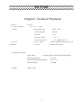
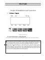
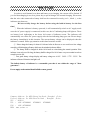
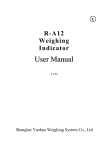
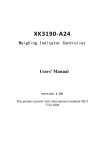
YH-T12E
Weighing Indicator
User Manual
V1.01
Shanghai Yaohua Weighing System Co., Ltd
YH-T12E
Table of Contents
Chapter I. Technical Parameter ............................................................. - 2 Chapter II Installation and Connection .................... 错误!未定义书签。
I.Indicator Diagram.......................... 错误!未定义书签。
II. Loadcell Connection ..................................... - 3 Chapter III Operation Instruction ................ 错误!未定义书签。
I. Start .......................................
II. Key Operation .............................
III. Weighing Operation ........................
Chapter IV Calibration Description .............
错误!未定义书签。
错误!未定义书签。
错误!未定义书签。
错误!未定义书签。
Chapter V Error Indication ................................. - 7 Chapter VII
Maintenance and attention.....................................................错
误!未定义书签。
Dear users:
Please read the manual carefully before using this indicator.
-1-
YH-T12E
Chapter I. Technical Parameter
1.Model
2. Class of Accuracy
3 Analog
YH-T12E
Class III 、n=3000
Input signal range
-19mV~19mV
Conversion speed
10 times/s
Gain drift
0.03%
Excitation voltage
Load cell connection
4 Display
considered)
Display range
division
DC 5V
1pcs 350Ω Load cell
-99999~999999 (decimal point is not
1/2/5/10/20/50 optional
5 Operating environment
Power supply
6 Weight
12v/500ma adaptor; 6V/4AH rechargeable battery
Operating temperature
0℃~40℃
Storage and transport temperature
-25℃~ 55℃
Relative humidity
≤85%RH
Approx. 0.4 kg
-2-
YH-T12E
Chapter II Installation and Connection
I. Indicator Diagram
(Figure 2-1) Front cover
II. Load cell & battery wiring diagram
1. The Load cell is connected through 6-pin plug socket (hole). Figure 2-2shows the meaning of each pin.
▲!The connections of Load cell and indicator must be reliable, and the shielded cable of Load cell
must be reliably grounded. Connections wires shall not be plugged and pulled when the indicator is
in a Power-up State in order to prevent static electricity damaging to the indicator or load cell.
▲!Since both Load cell and indicator are static-sensitive device, anti-static measures must be
practically taken in the use, and welding or other strong-electric operations on weighing platform
are strictly prohibited. In the thunderstorm season, reliable lightning protection measures must be
taken to prevent lightning damaging the senor and instrument and to ensure the operator safety and
the safe operation of weighing equipment and related equipment.
-3-
YH-T12E
Load cell wiring definition:
1:exciting +
2:signal+
3:shield
4:signal 5:exciting -
Battery wiring definition:
1:battery +
2:battery -
Figure 2-2 Load cell& battery interface
2. The connection of the external battery adopts 2-pin plug socket (hole).In the figure 2-2 ,battery+ connects
battery cathode and battery- connects battery anode.
Chapter III Operation Instruction
I. Startup&shut down
Press【on/off】button the indicator gets into self-check process after the power supply is connected. If
the weight on platform is within the startup zero setting range, it will enter automatic zero, and then the
-4-
YH-T12E
weighing status. If the weight on platform exceeds the zero setting range, the indicator will give tips and
display weight.
Press【on/off】button over 3 seconds, indicator display[ OFF ] and power off.
If the indicator battery voltage is lower than 5.8V , indicator alarm light is on please
charge the battery as soon as possible,if the voltage lower than 5.6V ,indicator can not work
properly and display [-LO--], if now still not charged the indicator will power off after half
minute automatically.
II. Key Operation
In the calibration status, some keys will perform the following functions:
1.[zero] key performs the "plus 1" function. After the ZERO key is pressed, the number displayed in the
last bit will be "plus 1", automatic zero will be made after it is added to 9.
2.TARE key performs the "shift" function. After the TARE key is pressed, the indicate light indicate bit will
move to the right for one bit, and will move to the highest bit automatically when it is in the smallest
bit .
3."# " key performs “input” function, after the # key is pressed the date will be input to indicator which
was set.
III. Weighing Operation
1. ZERO:
Press ZERO key to enable the data within zero setting range of indicator to return to zero. Zero
setting can be performed only after the STABLE light is on.
2. TARE:
When the displayed weight in weighing status is positive and the STABLE light is on, press the
TARE key to deduct the indicated weight as tare weight . In this case, the indicator will show a net weight
of "0" and the NET WEIGHT light is on. Press the TARE key again when gross weight is 0, the indicator
will clear the tare weight value.
【Note】Tare is not workable when gross weight is negative number.
3.
Accumulation :
Press the[Accu] key when the measured value is larger or equal to 20 divisions and the data is stable in
the normal weighing state, the indicator will perform "measured value manual accumulation" function. In this
case, the indicator will display the total accumulation data (in two steps): [total = ] (indicating that the content
shown below is the amount of accumulation data) will show the accumulation data [******] in about 1 second.
The times of accumulation will be then indicated (in two steps): [nub] (indicating that the times is shown
below) will show the times of accumulation [ ***] in about 1 second. The ACCUMULATION indicating
light is then on.
Note: the maximum weight of accumulation weight is ≤99999; The accumulation results will
be held before they are cleared and the data will not be lost after power-off. When the [*] key is
pressed, if the net weight is less than 20 divisions, only the accumulation value will be displayed,
-5-
YH-T12E
and the accumulation of weight and times will not be calculated.
4. Clear the accumulation result:
Press the CLEAR key in weighing state in a long time, the indicator will display [ CLr] and clear the
times of accumulation and the overall accumulation data. The user should clear first and then do the operation
in first time accumulation.
5. Power saving mode
If the indicator net weight is 0 and also stay in a stable status last 2 minutes, and
will come into power saving mode and display[
-], and indicator will exit this mode when
there is a weight change or button operation.
Chapter IV Calibration Description
Properly connect the signal source and power supply to preheat the indicator for 15-30 minutes when there is
no load on weighing platform.
After lead sealing is broken, please insert short connecting ring to connect pin JP2 on the indicator main
board, and allows the indicator to be calibrated. (circuit board is setting as default that allows
calibration, new indicator can omit this step),then operate as following steps(after calibration, lead
sealing again):
(1) Press【#】key during startup initialization(loosen before the self-inspection finished), the indicator will
come into calibration state.
1、 Division setting:
Display
【d
Display
Display
Display
Display
Display
Display
Display
Display
【d
【d
【d
【d
【d
【d
【d
【d
X 】
press【zero】key to choose 1、2、5、10、20、50,press【#】key for confirmation,
and will enter into next parameter setting, press【zero】 key for automatic
step-by -step cycle display.
X 】
01 】
02 】
05 】
10 】
20 】
50 】
01 】
For example, press【#】key when it shows【d
5】,now the division is setting to 5, and will come into
decimal point setting state automatically.
2、 decimal point setting :
Display 【dc
X】 press【zero】key to choose0、1、2、3,press【#】for confirmation, and will
come into next parameter setting automatically.
For example, press【#】key when it shows【dc
2】,now the decimal point setting is 0.00,and will come
into full capacity setting state automatically.
3、 Full capacity setting:
Display 【FULL
】 press【#】key to come into the number input state.
Display 【0 0 0 0 0 0】 press【tare】key,indicate symbol will move to right one step by step to which
-6-
YH-T12E
input position you want, and press【zero】to add value to adjust the number
you need until input the full capacity you need, and press【#】for confirmation
and indicator will come into next parameter setting.
For example, when it displays 【0 2 5 0 0 0】 press【#】key for confirmation and will come into zero point
setting calibration state.
4、 Zero calibration:
Display
【nOLOAD】
Insure there’s no loads on the platform and wait until the stable indicate
symbol display, then press【#】key,then will come into inner AD code state,
and press【#】again , and indicator come into full capacity calibration state.
5、 Full capacity calibration:
Display 【LOAD】
Put weights on the platform and press【#】key to come into input state
after stabilization.
Display 【0 0 0 0 0 0 】 Press【tare】key,the indicate symbol move to right and to the position which
can select number input, press【zero】key to add number and until input the
number you need .Now the indicator display value should as same as the
weight of the weights you load. And press【#】key for confirmation and
finish the full capacity calibration state.Now the indicator will display the
actual weight.
Display
【
End】
Note: Pull down the calibration short circuit ring from JP2 and re-seal after the
calibration .
Chapter V Error Indication
[Err
1]
Inner code loading is too small or the capacity of load cell is too large
[Err 2]
Out of manual zero setting range
[Err 3]
Zero position is too high or there is heavy goods on platform when startup.
[Err 7]
The calibration short-circuit ring did not connected
[Err 8]
Load cell signal line connect in reverse,please connect Load cell line in right way .
[------]
Out of display range , display value should between -99999~999999
[A
Out of the maximum times of accumulation or weigh of accumulation,
oL]
now the accumulation is not workable , please do the operation after clearance.
Chapter VI Maintenance and attention
1.To guarantee its clarity and service life, the indicator shouldn’t be placed directly under
sunshine and should be set in the plain space.
2.It is not suitable to place the indicator in the dusty and vibration environment and also avoid
-7-
YH-T12E
using in the moist environment.
3.Signal source and weighing indicator should be reliably connected, and system should be well
grounding. It should be far away with strong electric field, strong magnetic field. Load cell and
indicator should be far away with strong corrosive, inflammable, explosive object.
▲ Do not use under inflammable gas or inflammable steam; do not use under pressure
container canning system.
▲ Lightning frequent areas, it must be installed reliable lightning arrester, to ensure
operators safety and prevent damage of instruments and relevant equipment due to
lightning.
▲ Signal source and indicator are static sensitive equipments, when using must
earnestly adopt anti-static measure. It is prohibited in measuring device for welding
operation or other strong electric field operation; in thunderstorms season, we must
implement the reliable lightning-protection measures to prevent signal source and the
indicator damage caused by lightning strike, ensure operators safety of weighing
equipment and related equipment safety operation.
4. Never use strong solvents (e.g., benzene, nitro class oil) to clean the housing.
5.
Liquid or electricity conducting particles should not be poured into the indicator, in case the
indicator damage and electric shock.
6.
You should cut off power supply of indicator and relevant device before you pull-in and out
the connecting cable of indicator and external device.
You should cut off power supply before pull-in and out connecting cable of signal source.
7. Company advice for customers: start to use our indicator after test. The company is only
responsible for the quality of indicator, the biggest compensation is not more than twice of
indicator value, the company is not responsible failure of the whole system.
8.
Output interfaces of indicator must be strictly in accordance to the user's manual, you should
not alter any connection. If there is failure when using the indicator, you should
immediately unplug it, and send to manufacturers for repair. Ordinary non-professional
manufacturers should not repair it to avoid bigger damage.
9. Since invoice date, the indicator has a one-year free repair period. If any non-artificially
failure happens under regular using conditions within this period, the user can send the indicator
with its guarantee card (of the correct number) back to our service station or supplier for repair.
The indicator shouldn’t be open without a authorization, otherwise free guarantee will be
cancelled
10. Battery
① The battery will be charged after power cord is connected to AC 220V power supply. So
please remove the battery if it is not used frequently.
-8-
YH-T12E
In order to avoid internal over-heat and battery over-charging, the current will be limited. If
you feel that charging is too slow, please buy a special charger for external charging. Please note
that the wire ends connected to battery shall not be connected inversely (red +, black -), or the
indicator may burn out.
Be sure to fully charge the battery before using the built-in battery for the first
time!
② When the indicator is battery-powered, it will automatically switch to AC supply mode
once the AC power supply is connected; in this case, the AC indicating lamp will light on. There
are battery level indications at the lower left corner of indicator screen. The indicator will
automatically cut off the DC power supply after the last indicating lamp goes out. Please charge
the battery immediately in this situation. The current battery voltage can be displayed when the
indicator is started. Please pay attention to this data from time to time.
③ Please charge the battery for about 10-16 hours before its first use so as to avoid a too low voltage
caused by self-discharging of battery which may be mistakenly taken as failure.
④ The battery shall be charged for about 10-16 hours at a time during the normal operation. If the
indicator is not to be used for long, the battery shall be charged for 10-16 hours every two months in order to
extend its service life.
⑤ Four grade battery voltage display, and battery voltage are :6.19V、5.99V、5.77V、5.55V。The
indicator will turn off when the last light is off.
The built-in battery of indicator is a consumable part that is not within the range of "three
guarantees".
Power supply earth terminal should reliable contact ground
Company Address:No 4059 Shang Nan Road, Shanghai ,China
Factory Address:No 4239 Shen Du Road , Shanghai ,China
ZIP : 201112
TEL :(021)67282800
67282801
67282802
FAX :(021)67282826
WEB: www.yaohua.cc
-9-
YH-T12E
Sales hot line:
Tel :+86-21-67282822
Fax :+86-21-67282826
After sales hot line :
Tel :800 820 5030
+86-21-67282822
Fax :(021)67282810
Email:[email protected]
- 10 -