1
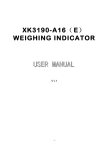
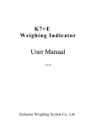
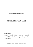
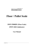
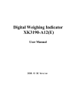
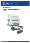
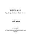
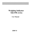
XK3190- A22
DIGITAL WEIGHING INDICATOR
USER MANUAL
Version: 2006.12
SHANGHAI YAOHUA WEIGHING SYSTEM CO.
CONTENTS
Chapter 1. Main Specification
1
Chapter 2. Display and keypad
2
2.1 front/back view and the interface part of the indicator
2.2 key functions
2.3 connect to load cell
Chapter 3. Operation
6
3.1 power on and auto zero setting
3.2 manual zero setting ( semi-auto zero setting)
3.3 tare
3.4 counting
3.5 accumulating function
3.5 parameter setup
Chapter 4. Maintenance and safety instruction
9
Chapter 5. Error message
10
Appendix I
11
Appendix II
12
Dear users,
Please well read the user manual before use the indicator.
X K 3 1 9 0-A22
Chapter 1. Main specification
1. Model: Weighing Indicator XK3190-A22
2. Accuracy: Grade Ⅲ, n=3000
3. A/D conversion method: Δ-∑
4. Sampling speed: 10 times/second
5. Load cell sensitivity: 1.5~3mV / V
6. Nonlinearity: ≤0.001%F.S
7. Load Cell Excitation Voltage: DC:5V
8. Full load temperature coefficient: ≤2.5 PPM/℃
9. Division: 1/2/5/10/20/50 optional
10. Maximum connection number of load cell: 4 load cells at 350Ω (with long distance compensation )
11. Keypad: mild touch off keypad, 5 function keys
12. Communication interface(optional): RS232C;Baud rate: 1200/ 2400/ 4800/ 9600 optional
13. Display: 6 bits LED display, 6 status indicating annunicator
14. Power supply: rechargeable battery DC6V/4AH (bAt-Lo will be showed as alarm when the voltage
is below 5.3V)
15. Operating temperature and humidity: 0~40℃;≤90%RH
16. Storage temperature: -25~55℃
(1)
X K 3 1 9 0-A22
Chapter 2. Display and keypad
2.1. FRONT / BACK VIEW AND THE INTERFACE PART OF THE INDICATOR
Front view
AC LOW VOL.
UNIT: kg
COUNT
FUNC
*
#
TARE
FUNC
STABLE
ZERO
*
TARE
ZERO
Back view
XK3190-A22 WEIHING INDICATOR
UNIT:kg
COUNT
FUNC
*
TARE
STABLE
ZERO
(2)
X K 3 1 9 0-A22
6V BATTERY
LOAD CELL
RS-232
POWER CABLE
POWER
FUSE
CALIBRATION SPAN KEY
(3)
X K 3 1 9 0-A22
2.2. KEY FUNCTIONS
2.2.1 [FUNC]: in weighing mode, press this key to switch between parameter setup and counting
mode
2.2.2 [*] in counting mode, press this key to start to input the sample number
2.2.3 [TARE]: Press this key to tare in weighing mode.
2.2.4 [ZERO]: Press this key to zero in weighing mode.
(4)
X K 3 1 9 0-A22
2.3 CONNECT TO LOAD CELL
2.3.1 A22 use 7-pin connector with 2.54mm pin distance to connect the load cell. The configuration
of each pin is described as below.
2.3.2 Adopt 6-pin shield cable for long distance compensation function.
2.3.3 ▲!Indicator must be reliably connected to Load cell and shielded-cable of load cell must be
reliably connected to underground. If indicator is powered on, the user should not insert or
withdraw the plug in order to protect the indicator and load cell.
2.3.4 ▲!Sensor and indicator are static sensitive devices; you must adopt anti-static measures.
The electric welding operation and other strong electric operation are prohibited. In order to
protect the operator, indicator, and relevant devices, you should install lightning rod in the
thunderstorm frequently happening area
DB9M configuration of load cell
7-pin connector configuration
red:excitation V+
pin 1:EX-
black:excitation V-
pin 2:S-
shield:
pin 5:SHELF
green:Output signal+
blue: Output signalyellow:Ex compensationwhite:Ex compensation+
pin
pin
pin
pin
6:EX+
7:S+
8:IN9:IN+
Please note: red pin and white pin, black pin and yellow pin must be both
short-circuited if the long distance compensation function is not used, otherwise the
indicator will not be able to performed well.
Please refer to the indicator external sticker for any pin color modification.
(5)
X K 3 1 9 0-A22
Chapter 3. Operation
3.1 POWER ON AND AUTO ZERO SETTING
3.1.1 The indicator will perform “999999-000000” to self-check when turning on. Then it will enter weighing
mode.
3.1.2 When power on, if loading weight on the scale deviates from the zero point, but still within zero set range,
the indicator will set zero automatically; if out of range, it is necessary to adjust the zero point or
recalibrate or reset.
3.2 MANUAL ZERO SETTING (SEMI-AUTO ZERO SETTING)
3.2.1 In weighing mode, when there is some error when unloaded, press [ZERO] to make the indicator to be zero.
3.2.2 If the displayed value deviates from zero point, but still within zero-range, pressing [ZERO] key is available.
Otherwise, [ZERO] key is invalid. (In this status, please recalibrate or reset zero parameters)
3.2.3 Only when stable annunciator is on, zero operation can be available。
3.3 TARE
When Indicator at weighing status, and displaying positive weight stable, press [TARE] key, indicator will deduct
the displayed weight value as tare weight. Then indicator displays net weight as “0 ”, and Tare sign annunciator is
on.
3.4 COUNTING
In weighing mode, press [FUNC] to enter counting mode, indicator will display ‘count’, press [ * ]
then it will display C00000, press [TARE] to select the triangle sign position. Press [ZERO] key,
The triangle sign will increase 1, input the sample number and place the sample on the platform,
press [ * ] after the stable annunicator on to enter the counting mode, it will display 0 and the
triangle sign correspond to the counting mode will be on. Press [ # ] to return the weighing mode.
The indicator will display ‘count’ after entering the counting mode, press [ * ] twice it will display
‘updata’ and directly enter the counting mode, the indicator will calculate and display through the
last sampling result. (During the process, if ERR4 is showed then the sampling result is < 0.25e,
sampling failed, the indicator will save the last sampling result. Or no sampling record is available,
last sampling result is 0.) Press [ # ] to quit the counting mode.
3.5 ACCUMULATING FUNCTION
In weighing mode, when the displayed weight is positive and stable, press [ * ] to accumulate the
current weight and display the accumulated weight(if the accumulated weight is >999999, then the
buzzer will alarm and display the last accumulated weight), the accumulate annunicator will be on,
press [ # ] to return the weighing mode , the indicator will also automatically return to the weighing
mode when accumulated weight displayed for 3~4 seconds, accumulate sign will be off.
(6)
X K 3 1 9 0-A22
The accumulate function will only effect again after the displayed weight back to zero. When the
accumulated weight is displayed, you can press [FUNC] to clear them in the memory, press [ # ] to
return the weighing mode. To check the accumulated weight of the memory, keep the scale
platform empty and press [*] to display the accumulated weight.
3.6 PARAMETER SETUP
In weighing mode, press [FUNC] to enter the user setting mode (mode P), it will display P-SET,
there are 10 modes from P1 to P10, press [*] to select the mode and press [TARE] to select the
parameter, press [#] to save and quit. The parameter is described as following:
1、P1
x
x=1:
Kg display
x=2:
Lb display
2、P2
3、P3
kg Lb switch
x
communication address
x=1:
01
x=2:
02
x=…
…
x=23:
23
x=24:
24
x
baud rate setting
x=9600:
baud rate 9600bps;
x=4800:
baud rate 4800bps;
x=2400:
baud rate 2400bps;
x=1200:
baud rate 1200bps。
please refer to appendix for bidirectional communication method
4、P4
x
digital filter intensity
x=1:
highest
x=2:
higher
x=3:
high
x=4:
low
x=5:
lower
x=6:
lowest
5、P5
x
RS232 output mode option
x=1:
no transmission(RS232 stop)
x=2:
continuous transmission
(7)
X K 3 1 9 0-A22
x=3:
continuous transmission in stable mode
x=4:
command mode
6、P6
x
battery saving mode
x=1:
not enabled
x=2:
auto saving mode
7、P7
x
x=0.5:
zero tracking scope
0.5e
x=1.0:
1.0e
x=1.5:
1.5e
x=2.0:
2.0e
x=2.5:
2.5e
x=3.0:
3.0e
x=5.0:
5.0e
8、P8
x
zero key scope
x=2:
2%FS
x=4:
4%FS
x=10:
10%FS
x=20:
20%FS
9、P9
x
zero scope upon starting
x=2:
2%FS
x=4:
4%FS
x=10:
10%FS
x=20:
20%FS
x=50:
50%FS
x=100:
100%FS
10、P10
x
backlight setting
x=on:
backlight on
x=oFF:
backlight off
(8)
X K 3 1 9 0-A22
Chapter 4 Maintenance and safety instruction
4.1 To guarantee indicator clarity and using life, the indicator shouldn’t be placed directly under
sunshine and should be set in the plain space.
4.2 The indicator can’t be placed into the place where the vibration is serious.
4.3 Load cell should connect with indicator reliably, the system should be well connected into ground.
The indicator must be protected from high electrical field and high magnetic field and keep away
from strong caustic, flammable and explosive objects.
▲! Do not use this device in an environment with flammable gas and steam; Pressure vessel canned
system is prohibited.
▲!The mounted lightning rod should be installed in order to assure the safety of the operator
and avoid damage to the indicator and relevant devices in frequent thunderstorm environments.
▲!Load cell and indicator are electrostatic sensitive devices; anti-static measures must be
performed during operation. It is prohibited to perform electric welding and other strong electric
field operations. Reliable lightning protection measures should be performed to avoid damage to
load cell and indicator, and to assure the safety of the operator, as well as the safe operation of the
weighing device and other relevant devices.
4.4 It is prohibited to clean the case of indicator with strong corrosive chemicals (such as benzene and
nitro oils)
4.5 Do not pour liquid or other conducting particles into the indicator, in order to avoid electric hazards
or damage to the indicator.
4.6 Power supply of the indicator and relevant devices must be turned off before plugging or unplugging
the connecting line of indicator and peripheral devices.
▲!Power supply of the indicator must be turned off before plugging or unplugging the connecting
line of the load cell.
4.7 Please note: please check the indicator before any usage. YAOHUA is only responsible for the
indicator quality and any compensation will be within 2 times price of the indicator, any
systematic problem with the indicator will not be under YAOHUA’s responsibility.
4.8 Indicator interfaces should be connected strictly according to the user manual, please do not connect in any
inappropriate way. When any trouble occurs, please pull out the plug immediately and send to the professional
factory for repair. Non-weighing instrument manufacturer please do not repair without permission in order to avoid
a worse situation.
4.9 From invoice date, the indicator has a one-year free repair period. If any non-artificially obstacle
about the indicator happens under correct using conditions within this period, the user is allowed to send
the product with its guarantee card (of the correct number) back to our corporation for free repair.
(9)
X K 3 1 9 0-A22
Chapter 5 Error message
Error message and measures for mis-operation
1.
Err 1
AD value is too small when calibrating (please select the load cell with
:
proper capacity)
2.
Err 2
Inputted weight data is 0 when full load calibrating in calibrating mode.
:
(Please input the correct weight data of the weights on the platform)
3.
Err 3
Zero position exceeds the setting range when turning the indicator on.
:
(Please ensure the weight on the scale is 0 when turning the indicator on)
4.
Err 4
5.
UPDATA
6.
bAt-Lo
Single weight is below 0.25e when sampling in counting mode. (Please
:
:
:
re-input the sample number)
Inputted sample number is zero when sampling in counting mode. (Enter
the counting mode after the UPDATA displayed for 1 second, operate
according to the previous sampling result, do not input 0 as the sample
number again)
Low voltage for the battery (please recharge)
(10)
X K 3 1 9 0-A22
APPENDIX I
Bidirectional communication method:
1. Command format:
02H
Adr.
Command
Nor.V-H
Nor.V-L
03H
initial character
communication address
command character
(Nor-Verify code),H is half higher byte
ASCII code,L is half lower byte ASCII code
terminate character
2. Calculation command character string
1) the communication address 1~24 of the indicator correspond with the capital letter A~Z of in
communication command sending, e.g.:01 is set as the communication address, then Adr.=A in communication
command
2) XOR verify code calculation method
(1)The data will get XOR character Nor.V through “ Adr.^ Command”
(2)Nor.V-H=XOR character Nor.V “ half higher byte”
(3)Nor.V-L=XOR character Nor.V “ half lower byte”
+30H
+30H
Command mode example:
e.g.: send the zero setting command “ 0(30H)” to the indicator, if the communication address is “ 1” ,
confirm sending the command character string.
The communication address is 1, then the sending communication address command character is “ A
(41H)” ;the XOR character is Nor.V=41H^30H=71H,则 Nor.V-H=7H+30H=37H,Nor.V-L=1H+30H
=31H at this time; so the final transmitting command character string is: 02H 41H 30H 37H 31H 03H
Zero setting command(30H) “ 0”
Tare command (0x54)“ T”
read Command: (0x52)or(0x72)“ R” or“ r”
3. data returning format
The data will be transmitted out in ASCII code when the instrument is in serial transmitting mode, 9 bytes
(include decimal point) for each data frame. Data transmitting is from lower byte to higher byte.0 is positive sign,
1 is negative sign, “ =” as list separator between each data frame, transmitting data content is same with the
displayed content on the screen.
(11)
X K 3 1 9 0-A22
Data returning format:
DATA
sign
=
weight data
±sign position
list separator
e.g.: the screen displays 31.900,then the indicator will continuously send 009.1300=009.1300=……
APPENDEX II
CALIBRATION
一、Press【#】when indicator start initialization,It will enter into the calibration.
1、 Division setup:
Display【d
X 】
Press【tare】key to choose1、2、5、10、20、50 for the division,press【#】
to confirm and the indicator will automatically enter into the next parameters
setup. Press【tare】key to automatically step up.
Display【d
1 】
Display【d
2 】
Display【d
5 】
Display【d
10 】
Display【d
20 】
Display【d
50 】
Display【d
1 】
E.g when show【d
5】,press【#】key,division was set to 5,and automatically to the decimal point
setup status.
Display【dc
X 】
press【tare】key to choose0、1、2、3,press【#】key to confirm,the indicator
will automatically enter into the setup of next parameter.
press【tare】key to automatically step up.
Display 【dc
0】
Display 【dc
0.0】
Display 【dc
0.00】
Display 【dc 0.000】
Display 【dc
0】
E.g when show【dc 0.000】,press【#】the decimal point was set by 0.000,then the indicator will
automatically enter into the full capacity setup status.
(12)
X K 3 1 9 0-A22
2、 Full capacity setup:
Display 【FULL 】
press【tare】 to enter into numeric inputting status.
Display 【0 0 0 0 0 0】
press【tare】,to move the ● signal right and select the numeric inputting
position, press【zero】key to automatically add 1 on the related position till you
get your required number, then press【tare】to move the ● signal right to
select the next numeric inputting position, press 【zero】key to automatically
add 1 on the related position till you get the final full capacity. Press【#】to
confirm it, the indicator will automatically enter into the next parameter
setup.
E.g when show【0 2 5 0 0 0】, press【#】to confirm,the indicator will automatically enter in to zero
calibrate.
3、 Zero calibrate:
Display
【nOLOAD】
There is no weight onside the platform,waiting for the stable signal● coming
and press【#】, the zero calibrate was finished, the indicator will enter into the
load weight calibrate status.
4、 Load weight calibrate:
Display
【AdLOAD】
Put the weight onside the platform and press【tare】to enter into the inputting
status.
Display
【0 0 0 0 0 0 】
press【tare】,to move the ● signal right and select the numeric inputting
position, press【zero】key to automatically add 1 on the related position till you
get your required number, then press【tare】to move the ● signal right to
select the next numeric inputting position, press 【zero】key to automatically
add 1 on the related position till you get the exact weight of what you have
put on. Press 【#】to confirm it, the indicator will automatically enter into
the next parameter setup.
Display
【End】
5、 Press【SPAN】inside the calibration span,indicator will save all the parameters and back to weighing mode.
(13)