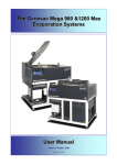
1
The Genevac HT- 8 & HT-12 Series II
Evaporation Systems
User Manual
Issue 1-9 – June 2008
Part Number 04-4541
Genevac HT-8 & HT-12 Series II Evaporating Systems
Contents
1
Introduction ........................................................................................................................................ 5
Amendment Control Form .................................................................................................................... 6
1.1
Safety symbols ..................................................................................................................................... 6
Genevac Evaporators and Combustible Solvents ............................................................................................. 6
2
System description and options ....................................................................................................... 7
3
3.1
3.2
3.3
3.4
3.5
Scope of delivery and installation ..................................................................................................... 8
Checking the delivery ........................................................................................................................... 8
Arranging commissioning ..................................................................................................................... 8
Training ................................................................................................................................................ 8
Positioning the evaporator .................................................................................................................... 8
Fitting the vacuum pump ...................................................................................................................... 9
4
4.1
4.2
Safety ................................................................................................................................................ 10
Safe loading of rotor ........................................................................................................................... 10
Safe loading of rotor – General Document ......................................................................................... 11
Nomenclature ..................................................................................................................................... 11
Use of Correct Accessories ................................................................................................................ 11
Adherence to Mass Limit .................................................................................................................... 12
Safe loading of sample holders into swings ........................................................................................ 12
Incorrect – Sample Holder rotated ...................................................................................................... 12
Correct – Sample Holder well seated ................................................................................................. 12
Incorrect – Sample Holder on edge of swing ...................................................................................... 12
Series I vs Series II Swings: ............................................................................................................... 13
Balancing of swings and sample holders. ........................................................................................... 13
Good procedural practice ................................................................................................................... 14
Safe door operation ............................................................................................................................ 15
Limitations of use ............................................................................................................................... 15
4.3
4.4
5
5.1
5.2
5.3
5.4
5.5
5.6
5.7
5.8
Getting started .................................................................................................................................. 15
How to switch on the pump ................................................................................................................ 16
How to switch on the evaporator ........................................................................................................ 16
Using the keypad ............................................................................................................................... 17
What the screens do .......................................................................................................................... 18
Sample Holder Type ........................................................................................................................... 19
Sample Volume .................................................................................................................................. 19
Solvent ............................................................................................................................................... 20
SampleGuard Control Temperature ................................................................................................... 22
SampleGuard Control Channel .......................................................................................................... 22
Coolheat Enable Pressure ................................................................................................................. 22
Chamber Temperature Control ........................................................................................................... 22
Rotor Speed ....................................................................................................................................... 23
Heat-Off Option .................................................................................................................................. 23
During a run ....................................................................................................................................... 24
How to enter control data ................................................................................................................... 27
How to use SampleGuard .................................................................................................................. 32
How to use the condenser .................................................................................................................. 34
How to start a run ............................................................................................................................... 36
6
6.1
6.2
6.3
6.4
Getting the best from your system ................................................................................................. 39
Routine Checks .................................................................................................................................. 39
Problem prevention ............................................................................................................................ 40
Optimising a run ................................................................................................................................. 41
Pre-programmed Runs ....................................................................................................................... 42
04-4541 Issue 1-9 – June 2008
Page 3 of 64
Genevac HT-8 & HT-12 Series II Evaporating Systems
7
7.1
7.2
7.3
7.4
7.5
Care of your system ......................................................................................................................... 43
How to clean the chamber .................................................................................................................. 43
How to change the pump fluid (CVP Only) ......................................................................................... 44
Maintenance and Service ................................................................................................................... 45
Additional equipment .......................................................................................................................... 46
Moving your system ........................................................................................................................... 47
8
Fault Finding ..................................................................................................................................... 50
9
Technical data ................................................................................................................................... 52
Mechanical data ................................................................................................................................. 52
Condenser ......................................................................................................................................... 52
Vacuum system .................................................................................................................................. 52
Vacuum pump - Scroll ........................................................................................................................ 52
Vacuum pump - CVP .......................................................................................................................... 52
Dimensions ........................................................................................................................................ 52
Operating ........................................................................................................................................... 53
Storage .............................................................................................................................................. 53
10
EC Declaration of Conformity ......................................................................................................... 54
11
Safety ................................................................................................................................................ 54
12
Warranty Statement ......................................................................................................................... 55
13
Annex A ............................................................................................................................................ 56
14
Useful information ............................................................................................................................ 64
These instructions are subject to change without notice.
No part of these instructions may be reproduced in any form or be processed, duplicated or distributed by electronic or optical means
without the written permission of Genevac Limited.
All rights reserved. © Genevac Limited
These operating instructions should be read before you use the Genevac HT-8 & HT-12 Evaporating System.
Keep them near the system for easy reference.
Your attention is drawn in particular to Section 4 Safety.
Page 4 of 64
04-4541 Issue 1-9 – June 2008
Genevac HT-8 & HT-12 Series II Evaporating Systems
1
Introduction
The Genevac Series II range of evaporation systems
are state-of-the art and represent a significant step
forward in evaporation technology for the R&D
laboratory.
Drawing on extensive experience in the drug
discovery field, the HT-8 and HT-12 systems are
designed to provide very high performance coupled
with ease of use.
As you will discover, the system is simple to set up,
easy to operate and very flexible.
The status of the system is displayed and controlled
on a single keypad, display module indicating the run
time, the vacuum, rotor temperature and chamber
temperature on digital displays.
Simple to use up-down controls enable the run time,
rotor and chamber temperatures to be set in an
instant and single push buttons set the other
functions.
HT-8 Rotor
04-4541 Issue 1-9 – June 2008
This manual will guide you through the start up
requirements, set up needs and operation of the
system to facilitate the most efficient procedure to
protect your product’s integrity and to ensure
optimum performance at all times.
Page 5 of 64
Genevac HT-8 & HT-12 Series II Evaporating Systems
Amendment Control Form
Revision
Number.
1.1
Issue and Reason for Change
Date Issued
1
Introduction of Warranty Statement
26 April 2004
2
Changes to Declaration of Conformity.
21 September 2004
3
4
5
6
Additional Technical Information regarding Power Supplies
Information on the correct use of SampleGuard Probes
Introduction of Auto Defrost and Drain Option
Introduction of Annex A – Getting the best from Auto Defrost and Drain
11 November 2004
28 September 2005
19 September 2006
15 September 2006
7
8
9
Converted to A5 Booklet
Add Maintenance of Rotor, Swings and Sample Holders
Update page footers
08 December 2006
09 April 2008
09 June 2008
Safety symbols
The following safety symbols are used throughout this manual. The definitions and scope of each symbol is
as described below.
WARNING
THIS SYMBOL INDICATES HAZARDS THAT CAN LEAD TO SERIOUS MATERIAL
DAMAGE OR POTENTIAL SERIOUS INJURY.
Caution
This symbol provides information about hazards that can be harmful to your
health or lead to material damage.
Note
This symbol provides information about technical requirements, which if not followed,
can lead to malfunctions, inefficiency and reduced productivity.
This symbol indicates that there may be a risk to sample integrity.
Genevac Evaporators and Combustible Solvents
Please note it remains the responsibility of the user to consider safety when evaporating any combustible
solvents and ensure the system is placed in a well ventilated environment. Genevac's position regarding
evaporation of such solvents, particularly with respect to the European ATEX directive, is available on our
website or from your local sales representative.
IMPORTANT
THIS SYSTEM MUST BE
EARTHED – SEE PAGE 53
Page 6 of 64
04-4541 Issue 1-9 – June 2008
Genevac HT-8 & HT-12 Series II Evaporating Systems
2
System description and options
Your HT-8 and/or HT-12 Evaporation System is
comprised of an evaporation chamber and rotor, with
an external a cryopump-condenser unit.
Vacuum is provided by the Scroll Pump, although
other types of vacuum pumps can be used.
Solid-state case heaters and Coolheat radiant lamps
heat the chamber and samples.
The control of chamber, bucket and sample
temperature, vacuum ramping rate, chamber
pressure, rotor speed and run time are all handled by
an embedded PC.
HT-8
The end user has the facility to auto program run
parameters for any (recognised) solvent/mixture
entered.
These optimised run parameters are
highlighted in Cyan on the display screen, when this
Auto Program facility has been selected.
Recognised Solvent(s) available from drop down
menu.
Sample Holder type available from drop down menu.
Lyophilisation (Freeze Drying) is available as a Rotor
Speed (Very Low (50g)) selection on evaporators
equipped for this configuration.
Please note: Lyophilisation samples are to be frozen
prior to being placed in evaporator.
HT-12
End of Run Prediction:
1
Heat Flow.
2
Sample Detection.
Auto Defrost & Drain is available, providing it was
specified at the time of placing the order.
The Run Progress screen now has a fully featured
graphical display, providing annotated plots for
temperature and pressure (now a log scale).
VC3000D Condenser
The control software enables the user to specify and
store a library of up to 100 different evaporation
profiles in an uncomplicated manner.
Run profiles can also be linked to provide multi stage
runs. Up to 100 different profile steps can be linked
and iterative loops can also be programmed.
With a maximum single run time of just below
100 hours, the system is extremely flexible to
meet every requirement.
CVP Pump
04-4541 Issue 1-9 – June 2008
Scroll Pump
Page 7 of 64
Genevac HT-8 & HT-12 Series II Evaporating Systems
3
Scope of delivery and installation
You will have purchased your system with or without
the option of commissioning by Genevac personnel
and possibly, without the option of a Genevac
vacuum pump and condenser.
Reference will be made in the following notes to the
installation procedures required to cover these
options.
On delivery, it is advisable to unpack your system at
the point of receipt, to ease the movement of the
component parts to the point of use.
3.1
Checking the delivery
Check the contents of the delivery as soon as
possible against the delivery note and notify
Genevac Ltd immediately of any missing or
damaged parts. (Refer to section 10 for contact
details).
3.2
Arranging commissioning
If your system is to be delivered separately, Genevac
Ltd will contact you prior to the delivery, to agree a
date to commission your system.
3.3
Training
Commissioning will normally include training in the
basic operation of the System. Further in house
training is recommended to fully exploit the flexibility
of the system.
THE HT-8/HT-12 EVAPORATOR MUST NOT BE
OPERATED BY PERSONNEL WHO LACK THE
TRAINING OR PROFESSIONAL EXPERIENCE TO
COMPREHEND THE HAZARDS THAT CAN ARISE
WHEN USING THE SYSTEM.
Personnel without such training require thorough
instruction. These operating instructions should form
the basis of this instruction.
3.4
Positioning the evaporator
POSITION THE EVAPORATOR AT LEAST 300 MM
AWAY FROM THE EDGE OF A BENCH AND THE
SAME DISTANCE CLEAR OF BREAKABLE
OBJECTS OR AREAS WHERE ENTRAPMENT
COULD OCCUR.
Page 8 of 64
04-4541 Issue 1-9 – June 2008
Genevac HT-8 & HT-12 Series II Evaporating Systems
IF THIS POSITIONING REQUIREMENT IS
IMPRACTICAL
THEN
THE
EVAPORATOR
SHOULD BE BOLTED TO THE BENCH OR
TROLLEY, BY ITS FIVE MOUNTING FEET, USING
M10 H.T. BOLTS ZINC.
GENEVAC SHOULD BE CONSULTED FOR
ADVISE
ON
ANY
OTHER
POSITIONAL
REQUIREMENTS.
3.5 Fitting the vacuum
pump
One of the following pumps will
have been supplied with your
system:
Scroll:
The Scroll pump supplied by
Genevac is only available as a
Non Recirculating model.
CVP:
The CVP 100 pump as
previously supplied by Genevac
was available in two formats:
the
standard
(Non
Recirculating) model or the
optional Recirculating model.
General
The Genevac pump supplied
with your evaporator will have
the
connecting
pipe/pipes,
fittings and power control lead
included with it.
Connect your vacuum pump to
the evaporator using the
connecting pipe and flange
fittings.
Connect the power and control
lead between the pump and the
socket on the rear of the
chamber.
If your system has been supplied with a Scroll pump then it must not be moved
between systems without first consulting Genevac Service for advise.
The Scroll pump will only function correctly on a Genevac Evaporator that has
been upgraded to work with the Scroll pump.
If your system has been supplied with a CVP pump then it must have an adequate supply of cooling
air and the hot outlet must have at least 300 mm of space beyond the hot air grille in the pump base.
It should not be placed in a cupboard without special precautions to ensure adequate cooling.
Consult Genevac Service for advice in such cases.
04-4541 Issue 1-9 – June 2008
Page 9 of 64
Genevac HT-8 & HT-12 Series II Evaporating Systems
4
Safety
BEFORE OPERATING THE SYSTEM, IT IS
IMPORTANT THAT THE FOLLOWING NOTES ARE
READ TO ENSURE THAT THE IMPLICATIONS TO
THE SAFETY OF PERSONNEL OPERATING THE
SYSTEM AND FOR THE PROTECTION OF SAMPLE
INTEGRITY ARE UNDERSTOOD.
•
•
There are important safety
and operational
considerations to be made
when positioning the
system.
Refer to Section 9
Technical Data for
recommended clearances
1.5 kg MAX including tubes, solvent,
sample, sample holder and swing
Samples in the chamber are subjected to
accelerations of up to 500G with a maximum load
capacity of 1.5 kg per swing.
The following precautions should therefore always be
observed.
4.1 Safe loading of rotor
Never exceed the maximum load capacity of 1.5 kg
per swing.
Balance pairs of sample holders that are loaded
opposite each other to within 10g (approximately).
Locate tubes correctly in tube holders.
Locate sample blocks correctly in sample swings.
Load two or four tube holders in opposite and
balanced configurations.
Distribute tubes in sample holders symmetrically.
Rotate the rotor by hand after loading and check that
all tube holders and plates are correctly located before
starting a run and before re-starting an interrupted run.
Do not load tubes or vials into sample holders other
than those types that have been approved by
Genevac Ltd.
Do not use sample holders that have not been
supplied with system without consulting Genevac
Service.
Refer to SampleGuard - Probe Positions document
available at:
http://www.genevac.com/applications/downloads1.html
for correct use of Sample Guard Probes.
Genevac Ltd will accept no
responsibility for any loss or damage
incurred by improperly or excessively
loaded rotors.
Page 10 of 64
04-4541 Issue 1-9 – June 2008
Genevac HT-8 & HT-12 Series II Evaporating Systems
4.2
Safe loading of rotor – General Document
Genevac are obliged to include the following information in its entirety, irrespective of the system type.
As with a centrifuge, a Genevac centrifugal evaporator must be loaded correctly to remove risk of damage.
Failure to correctly load a system can lead to loss of samples, system damage and significant downtime. This
guide is intended for new users and also as a reminder for more experienced users. The principles outlined
apply to all Genevac evaporators.
The document deals with various aspects of loading:
•
•
•
•
•
Use of correct swings and sample holders
Observation of weight limits
Safe loading of sample holders into swings
Balancing of swings and sample holders
Good procedural practice
Nomenclature
Firstly, it is important to understand what is meant by some of the terms that will be used in this document.
Most Genevac systems feature “swung” rotors.
(Some, however, feature “fixed” rotors, with many angled holes for individual tubes.
however is primarily concerned with swung rotors).
But this document
A swung rotor includes a swing or bucket. Below are drawings of typical swings for HT systems.
Open (or standard)
Side-Bridge
TM
Fast-Stack
(for microtitre plates)
Each of these swing types lifts straight out of the rotor. On large Mega systems, however (not shown here) the
swings are generally fixed in place and cannot be lifted out. Which swing is ideal depends on which sample
holder is required.
There is a large range of sample holders which sit in the swings, into which tubes, vials, beakers or flasks are
loaded.
Use of Correct Accessories
Genevac supply a wide range of sample holders to cover a variety of plate, tube, vial or flask formats. Where
no holder is available, custom units can be made. In a few cases worldwide, users have developed their own
holders and have collaborated with the Genevac R&D department to ensure the holders are suitable and
approved for use.
Important properties for a sample holder include:
•
•
•
•
•
Mass within prescribed maximum limit.
Closely matched mass within a set of holders.
Correct centre of gravity.
Good thermal conductivity.
Correct hole form and size tolerance to prevent tube or vial breakage under centrifugal force.
All Genevac holders are designed with these constraints in mind. Other 3rd party accessories may not be.
Generally, apart from microtitre plates, users are advised not to load non-Genevac holders into a system
without first checking with Genevac.
It is important that the swings and holders used are suitable for the Genevac system in use. For example,
there are some sample holders on sale for the Series II system that might appear to fit in a Series I system but
which would exceed the weight limitations. (See next section). If in doubt always ask Genevac before running
the system.
04-4541 Issue 1-9 – June 2008
Page 11 of 64
Genevac HT-8 & HT-12 Series II Evaporating Systems
There are also instances where a sample holder which is perfectly satisfactory (for the tube or vial it is intended
for) becomes unsuitable if used with something else, even though it might appear that the alternative tube fits
O.K. The Genevac Accessories Brochure indicates for each holder the maximum tube length that the holder is
designed to take, and these limits should always be adhered to. (It is available from the website,
http://www.genevac.com/brochure/GenevacAccessories.pdf)
Similarly some sample holders are intended for use in a Side-Bridge swing only, not in an Open swing, even
though they might appear to fit in the latter. The Accessories Brochure has a note “For use in Side-Bridge
Swing” by these items, but if in doubt, ask Genevac.
Some users wish to run Genevac systems using the “Bohdan Miniblock” system as their sample holder. Please
note, some (not all) of this range of items significantly exceed the mass limitations of a Genevac system. If you
plan to use Bohdan Miniblocks in a Genevac system, please contact Genevac for a list of the relevant weights.
Adherence to Mass Limit
There is a maximum mass that can be loaded onto each position of a Genevac swung rotor, this total includes:
•
•
•
•
The swing
The sample holder
The tubes or vials
The sample solutions
Under no circumstances should this be exceeded.
If in doubt what your combined mass total is, load up a full swing and weigh it.
In most cases, with normal solvent volumes, any sample holder currently on sale from Genevac will fall within
the mass limit for a Series II system.
Safe loading of sample holders into swings
Applicable where both Series I and Series II evaporators are being used within the same laboratory.
There are two ways that it is possible to misload a sample holder into a swing.
One (shown below) is to rotate the sample holder such that it rests on the edges of the swing.
Incorrect – Sample Holder rotated
Correct – Sample Holder well seated
Another mode of misloading is illustrated below.
Incorrect – Sample Holder on edge of swing
Correct
Both these modes of misloading are possible with an older version of the Open or standard swing but are
virtually impossible with the new design of swing, all Series II systems feature the new design of swing. The
following illustration shows the difference.
Page 12 of 64
04-4541 Issue 1-9 – June 2008
Genevac HT-8 & HT-12 Series II Evaporating Systems
Series I vs Series II Swings:
The older Series I design is easy to distinguish
because the corners are not welded.
The newer (“Series II“) swing has angled sides
that make the incorrect loading illustrated
above virtually impossible. Care still has to be
taken though.
It also has rounded and welded corners.
Genevac offer a low cost upgrade to any user who has the old type of swing and who wishes to avoid the
possibility of this misloading ever occurring
Balancing of swings and sample holders.
Opposite pairs of swings need to be balanced within specification and that the swings are of the same type and
version. Please note that there are several versions of Side Bridge Swings in circulation with a static weight
ranging from 375g to 445g. Ensure that swings of the same static weight are positioned diametrically opposite
in the rotor; ideally use the same version of swings in all four position of each rotor. Genevac systems have
some inbuilt tolerance for imbalance and a system for shutting off if the out-of- balance is unacceptably high but
it is advised that the user aims for no more than 10g imbalance between opposite pairs of swings.
Where it is necessary to make “dummy” samples to balance real loads, the balancing load should be of a
similar solvent composition. For example, do not balance 200g of 50/50 Water/Acetonitrile with 200g of water,
because partway through the run, when the acetonitrile has all gone but the water has barely started
evaporating, the system would be 100g imbalanced.
Note that with a system such as the Fast-StackTM swing, balancing is slightly more complex. Suppose a “FastStackTM Deepwell” swing is used with two 96 well microtitre plates, 2ml per well. (The Fast-StackTM swing is
illustrated on the first page of this document). In one swing, the lower microtitre plate is empty, the upper
microtitre plate is full, 1.8mls per well. On the other swing, the reverse is true.
The two swings now weigh the same, but if
placed opposite each other in a system, would
not be balanced, because when the swings
rotated to their operating attitude, the centre
of mass of one is at a different radius to that
of the other.
This effect becomes very significant when balancing multi level swings in large Mega systems.
It is also preferable not to run with only two swings out of four present on any one level of the rotor. If there are
only two swings’ worth of samples, you should still load swings and empty sample holders in the other
positions. This ensures the rotor is evenly loaded.
04-4541 Issue 1-9 – June 2008
Page 13 of 64
Genevac HT-8 & HT-12 Series II Evaporating Systems
Good procedural practice
Finally, there are a few general rules for safe operation of a system:
•
•
•
•
•
•
Ensure only users familiar with all the issues outlined in this document are permitted to operate the
equipment.
Only load swings and sample holders approved by Genevac.
System should be loaded and started by the same person.
Never leave system unevenly loaded and close the door. Someone may start it.
Never start, or restart a system without checking it is evenly loaded, all sample holders are correctly seated,
all swings are swinging freely.
Refer to SampleGuard - Probe Positions document available at:
http://www.genevac.com/applications/downloads1.html
for correct use of Sample Guard Probes.
Misloading may result in damage to samples and the machine, and could void the warranty.
Page 14 of 64
04-4541 Issue 1-9 – June 2008
Genevac HT-8 & HT-12 Series II Evaporating Systems
4.3 Safe door operation
The door is opened and closed manually but locked
automatically by an electric actuator.
Close and hold the door firmly against the door seal
and press and hold the Door Close switch.
A single audible beep indicates that the door is
locked and it is safe to proceed.
A proximity switch will prevent the mechanism from
locking if the door is not closed.
Hold the door firmly against the door seal whilst
holding down the Close Door switch.
Note that the door mechanism will NOT work if the
condenser is not connected to the system.
4.4 Limitations of use
Your HT-8/HT-12 Series II evaporating system is
unsuitable
for
use
under
the
following
circumstances.
•
With strong mineral acids such as HCl and HBr
at all concentrations, unless specifically built to
order.
•
EVAPORATING
DIETHYL
ETHER
AND
OTHER SIMILAR LOW FLASH POINT
SOLVENTS WITHOUT A GENEVAC INERT
PURGE FITTED TO THE EVAPORATOR AND
PUMP.
For use as a pressure vessel.
5
Getting started
The following notes describe the basic start up, set
up and run instructions for your HT-8/HT-12
evaporating system.
When the Genevac vacuum pump is fitted, the
chamber is powered from the pump and so it is only
necessary to connect the pump to a suitable mains
power supply.
04-4541 Issue 1-9 – June 2008
Page 15 of 64
Genevac HT-8 & HT-12 Series II Evaporating Systems
5.1 How to switch on the pump
Connect the pump to the mains and switch on the
mains.
Switch the pump mains switch on.
Scroll
The pump will not be ready for use until the green
ready light on the front panel is illuminated (Approx 7
minutes) – but power is available to the evaporator.
The system will not be available for use until the
vacuum pump has reached the correct operating
temperature (about 25 – 30 minutes for the Scroll
pump. This only occurs when the system is first
switched on or when the Auto Stop function has
been used), (5 – 10 minutes for the CVP).
CVP
5.2 How to switch on the evaporator
Switch the mains switch on.
The screen will display the Software Control
screen.
Press the START key on the keyboard to access the
Select Run screen.
The Select Run screen will load up at the last run
that was used.
A series of runs have been preloaded from RUN
51 to RUN 100 inclusive.
Runs 51 to 98 provide a range of Standard
Configurations.
Runs 99 and 100 are only for use by engineers for
Maintenance/Diagnostics.
The condenser will be powered up when the
chamber is switched on.
There will be a slight delay until the condenser
reaches the correct temperature.
Page 16 of 64
04-4541 Issue 1-9 – June 2008
Genevac HT-8 & HT-12 Series II Evaporating Systems
5.3 Using the keypad
The Series II keyboard controls and displays have
been designed for ease and simplicity in use.
The keyboard has the most used function keys on
the left hand side.
The right side illuminates when the RUN DATA
screen is accessed.
The START and STOP keys start and stop a
selected run.
The cursor direction keys move you around the
screen in the direction of the arrows.
The ENTER key is used to ‘open’ and ’close’ a field
on the Run Data screen when inputting or amending
data.
Note that the START key also acts as an ENTER
key when the keyboard is not illuminated.
Operating the MENU key displays the USER MENU
screen only when the rotor is not spinning and the
chamber is vented.
MENU
Operating the DISPLAY key displays the RUN LOG
screen only when a run is in progress or has
finished.
DISPLAY
Operating the SETTINGS key displays the RUN
DATA screen only for the selected run.
SETTINGS
Note that the RUN DATA screen can also be
accessed from the menu VIEW/EDIT DETAILS
option on the SELECT RUN screen when a run is
not in progress.
The following notes describe the function of each of
each screen and provides an explanation of the
prompts displayed.
04-4541 Issue 1-9 – June 2008
Page 17 of 64
Genevac HT-8 & HT-12 Series II Evaporating Systems
5.4 What the screens do
There are three main control screens.
The SELECT RUN screen lists the library of
evaporation profiles you can choose.
This screen has the capacity to store 100 different
profiles, from which you can select a particular run or
set of runs.
The screen is accessed after switching on the pump
and evaporator and by pressing the START key on
the keyboard.
•
You store and select
your runs on these
screens.
•
Use the UP and
DOWN cursor keys
to move between
profiles.
By moving across the
horizontal menu bar,
•
You can START a
run.
•
You can VIEW and
EDIT a profile.
•
You can CLEAR a
profile.
•
You can COPY a
profile.
•
Start to DRAIN.
•
Start to DEFROST.
•
Start to FLUSH.
(If Option Fitted)
•
Adjust
OPTIONS.
your
The 100 profiles are shown on this and nine other
screens.
The other screens can be accessed quickly by
moving the cursor down to the last entry on the page
and pressing the down cursor key.
This will take you to the last entry on the next page.
Alternatively, use the up cursor key.
Page 18 of 64
04-4541 Issue 1-9 – June 2008
Genevac HT-8 & HT-12 Series II Evaporating Systems
Each line on the SELECT RUN screen is generated
from the RUN DATA screen.
When the chamber is vented and the rotor stationary,
this screen is accessed by selecting VIEW/EDIT at the
foot of the SELECT RUN screen and pressing START.
When the system is running, the RUN DATA screen
can be accessed directly by pressing the SETTINGS
key.
SETTINGS
•
Use the UP and
DOWN cursor keys
to move between
fields.
•
Press ENTER to
‘open’ a field, make
the entry and press
ENTER again to
‘close’ the field.
•
During a run, you
access this screen
by pressing the
SETTINGS key.
•
You can edit any
parameter during a
run in this way.
•
Toggle Run Data
Locked to protect
your data.
Please note that Main Menu order has changed.
It now reads:
Sample Holder Type, Sample Volume
Solvent
Sample Holder Type
•
When selected you
are presented with
the
SAMPLE
HOLDER menu.
•
Use Cursor keys to
move up and down.
•
Press ENTER to
select.
•
Select your sample
holder type or if not
defined,
select
Other and enter
the details.
Sample Volume
•
04-4541 Issue 1-9 – June 2008
Select and
value(s).
enter
Page 19 of 64
Genevac HT-8 & HT-12 Series II Evaporating Systems
Solvent
When you select this
field you are given a list
of solvent types that
have already been
programmed into the
evaporator.
Use cursor keys
move up and down.
to
Press ENTER key to
select (Highlighted in
blue).
Please note that the
solvent(s) that you have
selected from the menu
appear in the bottom
left corner of the
screen.
Select Done
finished.
when
Once your selection has been made you are now
given a new option to Auto Program the remaining
run parameters.
Press Y to accept Auto
Program.
If you have entered an
unrecognised solvent by
selecting Other from the
solvent menu, you will
not be presented with
the option to Auto
Program.
Genevac and the ATEX Directive:
Please note that it remains the responsibility of the user to consider any solvents being evaporated within the
context of the ATEX directive. The presence of solvents on the list above indicates only that they will not
damage the system. If further information is required, please contact your Sales Representative or visit
http://www.genevac.com/
Page 20 of 64
04-4541 Issue 1-9 – June 2008
Genevac HT-8 & HT-12 Series II Evaporating Systems
With Auto Program
Y[es] selected.
The screen will now
display
the
Auto
Programmed data in
Cyan (Light Blue).
Save Run and continue
If you did not select
Auto Program or were
not given the option,
due to inputting an
unrecognised solvent,
then
you
will
be
presented
with
this
screen.
If editing an existing run,
parameters will remain
as previous settings.
If creating a new run,
parameters will be set to
safe default settings.
04-4541 Issue 1-9 – June 2008
Page 21 of 64
Genevac HT-8 & HT-12 Series II Evaporating Systems
SampleGuard Control
Temperature
Set within the range of 20 to 70°C.
SampleGuard Control
Channel
Channel 1 in Swing or
Sample Holder.
Channel 2 in Sample.
Coolheat Enable
Pressure
Set within the range of
5–400 mbar.
.
Chamber Temperature
Control
There are now 3 options
available:
Wait for Chamber to
Heat
Range
45°C.
from
0°C
to
Wait for Chamber to
Cool
Range
45°C.
from
0°C
to
Automatic Control
Temperature
is
automatically set to an
optimised figure for the
recognised solvent /
mixture selected.
Page 22 of 64
04-4541 Issue 1-9 – June 2008
Genevac HT-8 & HT-12 Series II Evaporating Systems
Rotor Speed
There are now 3 options
available:
High
Rotor speed applies
nominally 500 G.
Low
Rotor speed applies
nominally 300 G.
Very low
Rotor speed = 500 rpm,
applies nominally 50 G.
SampleGuard
Coolheat
are
available.
and
not
Heat-Off Option
There are now 2 new
options available:
Heat Flow
Automatically
detects
dryness by monitoring
the rate at which the
solvent is evaporating.
Low solvent loading or if
the lamps are turned off
may cause Heat Flow to
fail.
If failure occurs, select
one of the other two
options.
Sample Detection
Monitors
the
temperature difference
between
the
2
SampleGuard channels.
Notes on the use of optional end of run Automatic Defrost and Drain can be found in item 13, Annex A; Getting
the best from Auto Defrost Drain.
04-4541 Issue 1-9 – June 2008
Page 23 of 64
Genevac HT-8 & HT-12 Series II Evaporating Systems
During a run
The main section of the RUN LOG screen, gives a
graphical display of the real time changes in
chamber pressure, spin rate, sample and sample
holder temperatures.
The top left hand section, displays the current
temperatures of channels 1 and 2, the chamber
temperature, the condenser temperature, the
chamber pressure, the total time elapsed and the
stage time elapsed if linked runs are being
undertaken.
NOTE THE NEW GRAPHICAL
DISPLAY.
•
The RUN LOG screen
displays the real time
events.
•
The top left block gives
current values.
•
The top right block displays
any alarms.
•
The block at the foot of the
screen displays the current
status of the system and
Instructions.
•
Pressure is plotted on log
scale.
•
Press STOP to terminate a
run at any time.
When run enters final drying
period the display changes to
indicate the time left to End of
Run or if linked runs End of
Stage.
Press the DISPLAY key during a
run to return to the RUN LOG
screen.
Operating the STOP key at any
time during a run will terminate
the run.
The chamber will vent and the
rotor will start to spin down.
You will not be able to open the
chamber until the chamber has
reached atmospheric pressure
and the rotor has stopped
spinning.
Run finished press < > to view data.
any other key to end.
Page 24 of 64
When the chamber has vented
and the rotor stopped, you will be
given this STATUS prompt.
04-4541 Issue 1-9 – June 2008
Genevac HT-8 & HT-12 Series II Evaporating Systems
When the run is finished, after pressing a key, the
following screen is displayed.
Select the DRAIN or DEFROST OPERATIONS
option using the numeric keys.
Press ENTER to
DEFROST MENU.
display
the
DRAIN
or
•
With
the
DEFROST
CYCLE
highlighted,
press ENTER to start the
defrost cycle.
•
This will automatically
open the defrost valve.
•
Open the manual drain
valve to drain the
condenser
when
prompted.
•
Drain the condenser
after every run and at the
end of the day.
•
A defrosted and drained
condenser will operate
more efficiently.
•
Periodically check the
level of solvent in the
containers attached to
the drains.
Screens similar to this are
also displayed for DRAIN
and, if fitted, the FLUSH
option.
04-4541 Issue 1-9 – June 2008
Page 25 of 64
Genevac HT-8 & HT-12 Series II Evaporating Systems
If you wish to end the work session on the system,
go to the Select Run screen and press STOP.
This prompt will be
displayed
on
the
SELECT RUN screen.
Press Y to close the
system down or N to
select another run.
Page 26 of 64
•
The SHUT DOWN
screen
will
be
displayed when you
select
the
Y
response.
•
The pump will be
purged of solvent
vapours
for
30
minutes.
•
You can restart the
run
by pressing
START at any point.
•
You
can
abort
Shutdown
by
pressing START at
anytime.
•
If you want to start a
different run, press
STOP, select N and
press ESC to display
the SELECT RUN
screen.
04-4541 Issue 1-9 – June 2008
Genevac HT-8 & HT-12 Series II Evaporating Systems
•
The USER MENU
displayed by pressing
MENU key only when
chamber is vented and
rotor stationary.
•
Lamp Layer Selection is
not an option for the HT-4
or Mega.
•
In Operator Controls you
can adjust the screen
brightness to suit your
viewing angle.
•
You can turn the audible
warning off or on.
•
Press ESC to leave this
menu
is
the
the
the
Use the cursor keys to select
the OPERATOR CONTROLS
and press ENTER.
5.5
•
Use the UP and DOWN
cursor keys to adjust the
screen brightness to suit
your viewing angle.
•
Toggle the beep ON or
OFF.
•
Press ESC to exit this
screen.
How to enter control data
All control data is entered from the RUN
DATA screen.
From start up of the system and the
software control screen, press START to
display the SELECT RUN screen.
Select the VIEW/EDIT DETAILS option and
press START to display the RUN DATA
screen.
Use the UP and DOWN cursor keys to
move between fields.
Unless otherwise stated, press ENTER to
‘open’ a field, input your requirement and
press ENTER again to ‘close’ the field.
04-4541 Issue 1-9 – June 2008
Page 27 of 64
Genevac HT-8 & HT-12 Series II Evaporating Systems
Run Data Locked
When set to Yes this setting protects the run data
from inadvertent corruption.
Press the ENTER key to toggle between Yes and
No.
Note that you will not be able to make amendments
or additions if the data is locked.
Lock the data after completing the run entry.
Next Run Number
This control enables you to link and loop runs in any
sequence.
If you want to link runs, list the number of the run you
want to follow the run you are entering.
Repeat this process for any subsequent runs you
would like to link.
You can also loop a run.
The limitation of how many runs you can link will be
either the maximum run time of 99 hours 59 minutes
or 99 different steps.
Linked and looped runs can always be interrupted by
manually stopping the system.
Use the DOWN cursor key to move to the next field.
Run Name
Enter the title of the run that should be no more than
20 characters long.
Use the DOWN cursor key to move to the next field.
Sample Holder Type
Press ENTER to display the Select Sample Holder
drop down menu.
Use the UP and DOWN cursor keys to select the
option and press ENTER.
If OTHER is selected, the description should be no
more than 20 characters long.
Sample Volume
Solvent
Press ENTER and input the volume in mls.
Press ENTER to display the Solvent Drop down
menu.
Use the UP and DOWN cursor keys to select the
option(s) and press ENTER.
Once your selection has been made select Done
and press Enter, you are now given a new option to
Auto Program the remaining run parameters.
If OTHER is selected, the name should be no more
than 31 characters long, press ENTER to return to
Solvent drop down menu.
Page 28 of 64
04-4541 Issue 1-9 – June 2008
Genevac HT-8 & HT-12 Series II Evaporating Systems
Select Done and press ENTER.
SampleGuard Control Temperature
NOT AVAILABLE FOR LYOPHILISATION
(Very Low rotor speed)
Press ENTER and input the temperature you wish to
limit the sample to during evaporation.
This can be in the range of -20 to +70° C.
Note that if not specified, the default setting is 30° C.
Note this is not available for Lyophilisation.
Sample Guard Control Channel
Press ENTER and input the channel on which you
want to control temperature.
NOT AVAILABLE FOR LYOPHILISATION
(Very Low rotor speed)
Channel 1 will normally be assigned to the probe in
the sample holder and channel 2 to the probe in the
sample.
Note that when powered down, this setting defaults
to channel 1 as the control channel.
Note this is not available for Lyophilisation.
Coolheat Enable Pressure
NOT AVAILABLE FOR LYOPHILISATION
(Very Low rotor speed)
Press ENTER and input the pressure below which
you want the lamps to be turned on.
This can be in the range of 5-400 mbar.
If nothing is selected, the setting will default to 400
mbar.
Note this is not available for Lyophilisation.
Chamber Temperature Control
Press ENTER and Select the method from the 3
options displayed:
Wait for Chamber to Heat
Range from 0°C to 45°C.
Wait for Chamber to Cool
Range from 0°C to 45°C.
Automatic Control
Temperature is automatically set to an optimised
figure for the recognised solvent / mixture selected.
Input the minimum temperature you want the
chamber to reach before spin-up will commence.
04-4541 Issue 1-9 – June 2008
Page 29 of 64
Genevac HT-8 & HT-12 Series II Evaporating Systems
Rotor Speed
Press ENTER to display the Select Rotor Speed
drop down menu.
Use the UP and DOWN cursor keys to select High,
Low or Very Low (optional at order).
High speed applies nominally 500 G and Low speed
nominally 300 G.
Very Low applies nominally 50 G at a very low rotor
speed.
Selecting the Dri-Pure option described later will
over-ride this option and sets High.
If nothing is selected, the setting will default to LOW
speed.
Heat-Off Option
Select either: Elapsed Time, Heat Flow or Sample
Detection.
For Elapsed Time enter value in hours and/or
minutes
Heat Flow
Only requires 1 SampleGuard probe.
This MUST be used to control the sample holder or
swing temperature.
NOTE:
Control Channel Probe
MUST be placed in the swing OR SAMPLE
HOLDER
Either channel 1 or channel 2 may be used, ensure
that the channel chosen is selected as the control
channel in the run options.
Automatically detects dryness by monitoring the rate
at which the solvent is evaporating.
Low solvent loading or if the lamps are turned off
may cause Heat Flow to fail.
If failure occurs, select one of the other two options.
For very low solvent loading, requiring very little
heat, then the following would be used:
Sample Detection
Requires both SampleGuard probes, Channel 1 to
monitor the swing/holder temperature and Channel 2
in the centre well of the sample holder to monitor
sample temperature.
Monitors the temperature difference between the 2
channels.
At the start, they are the same, but as the samples
dry the temperature difference gets smaller.
When the temperature difference reaches the preset
figure (Not user configured), the run is terminated.
Page 30 of 64
04-4541 Issue 1-9 – June 2008
Genevac HT-8 & HT-12 Series II Evaporating Systems
Heat-Off Elapsed Time
This can be in a range of 0 (lamps off for the entire
run) to 99 hours 59 minutes.
End-of-Run Option
This option is the elapsed time after which the run
will be stopped.
End-of-Run Elapsed Time
Press ENTER and input the time after which you
want the run to stop.
This can be in the range of 1 minute to 99 hours 59
minutes.
End of Run Defrost and Drain
Pressure Control Regime
Press ENTER to toggle between Yes and No. Only
available between linked runs and is typically used to
remove mixed solvents – See Annex A Page 55.
Press ENTER to display the Select Pressure
Control Option drop down menu.
Use the Up-Down cursor keys to select the pressure
option required.
Full Vacuum
Full Vacuum will take the chamber pressure down
to the vacuum capability of the pump.
Controlled Pressure
When the Controlled Pressure option is selected,
the Controlled Pressure field will be displayed.
Move down to this field using the DOWN cursor key
and press ENTER.
Input the pressure you want the chamber to be
limited to in the range of 0 to 500 mbar.
Dri-Pure
NOT AVAILABLE FOR LYOPHILISATION
(Very Low rotor speed)
DRI-PURE
reduces
the
vacuum
over
a
predetermined period to 50 mbar, then goes to the
control pressure as set by the user.
This feature is particularly useful in preventing
bumping, (the violent boiling of solvents), resulting in
solvents being expelled, which is a source of cross
contamination of samples.
Bumping can also cause products to be deposited on
the glass lenses of the Coolheat lamps, which
eventually results in breakages.
Note that during the DRI-PURE cycle, which is
approximately 40 minutes, the Coolheat function will
be disabled.
Variable Dri-Pure
NOT AVAILABLE FOR LYOPHILISATION
(Very Low rotor speed)
Variable Dri-Pure allows the user the option to set:
1) The pressure at which the vacuum ramp will
start.
2) The pressure at which the vacuum ramp will end.
3) The total duration of the vacuum ramp.
4) Final Controlled Pressure.
04-4541 Issue 1-9 – June 2008
Page 31 of 64
Genevac HT-8 & HT-12 Series II Evaporating Systems
5.6
How to use SampleGuard
SampleGuard is a dual channel temperature
controller that operates when the rotor is spinning.
Thermocouple type probes are connected to the
SampleGuard housing as shown.
One probe is used to control the sample holder
temperature and the other the sample temperature.
The SampleGuard housing is stamped next to the
connectors to identify channels 1 and 2.
The third connection is for a remote power supply to
power SampleGuard to verify temperature calibration
(refer to later notes).
Always ensure that channel 1 is used to monitor and
control the sample holder temperature and channel 2
to control the sample temperature.
Always use channel 1 as the control channel as
using channel 2 under these circumstances, could
result in damage to thermo labile samples.
Depending on the solvents being evaporated and the
conditions, significant cooling and/or freezing will
normally occur.
Under these conditions using microtitre plates, it is
advisable to position the sample probe in a sample
well near the centre of the plate.
Since the central wells are surrounded by other
frozen or cold wells, there will be a significant
thermal drain.
Under these conditions, dryness may well occur in
the outer wells whist the central samples remain in
solution or frozen.
The use of Genevac Heat Transfer Plates would prove to be beneficial in preventing this
condition arising, by providing an even heat transfer to your samples.
Please refer to our “Options & Accessories Brochure” to get the best solution for needs.
Available in pdf format, as a download, from our web site: http://www.genevac.co.uk/
Page 32 of 64
04-4541 Issue 1-9 – June 2008
Genevac HT-8 & HT-12 Series II Evaporating Systems
When positioning the sample probe, always ensure
that the probe tip is located firmly at the bottom of
the well, vial or tube.
Note that the term TxD indicates that the transmitter
is not transmitting and will be displayed when the
rotor is not rotating.
The control temperature can be changed during a
run by pressing the SETTINGS key to display the
Run Data screen.
Use the cursor keys to select the SampleGuard
Control Temperature field and press ENTER.
Input the new value and press ENTER again.
The system will prompt you to confirm the change
when you leave the Run Data screen.
Press Y for yes and N for no.
To verify the calibration of SampleGuard, remove the
Stuffer Plug shown, connect the remote power lead
and connect probes to channels 1 and 2.
With the door open, immerse both probes in a
beaker of water at approximately 40 degrees
Centigrade.
Press the START key and verify the indicated
temperatures
against
a
calibrated
digital
thermometer.
The frequency of verification and record retention,
should meet the requirements of your ISO/EN/BS
9000 series or NAMAS procedures.
On removal of the remote power lead, always ensure
that the Stuffer Plug is replaced.
SampleGuard will not operate without the Stuffer
Plug.
04-4541 Issue 1-9 – June 2008
Page 33 of 64
Genevac HT-8 & HT-12 Series II Evaporating Systems
5.7
How to use the condenser
The VC3000D condenser fitted to your system has
two condensing pots.
The vacuum pot of 3 litre capacity, is connected in
line between the evaporation chamber and the
pump.
The exhaust pot of 1.5 litre capacity operates at
atmospheric pressure and is connected in line
between the vacuum pump exhaust, with the outlet
vented to suitable fume extraction.
The condenser is powered directly from the chamber
and is powered up when the chamber is switched on.
MANUAL DEFROST/DRAIN
The only controls on the condenser are the drain
valves for the vacuum and exhaust pot drains and
the flush unit valve, if fitted.
The ready light will illuminate after a short period, to
indicate that the condenser has reached operating
temperature.
Condenser temperature is displayed on the
condenser front panel and also on the RUN LOG
screen (refer to page 18).
Note that due to sensor positions, there may be a
difference between the indicated temperatures on
the condenser and the evaporator.
The DEFROST/DRAIN CYCLE for the condenser is
accessed through the USER MENU screen detailed
on page 21.
To defrost, display the DEFROST/DRAIN/FLUSH
menu and use the cursor keys to select the
DEFROST VALVE and press ENTER.
The screen prompt will change to Open and the
condenser temperature will start to increase.
Note that the defrost cycle will only be necessary for
solvent mixtures that freeze at the operating
temperature of the condenser, typically –45°C.
NEVER OPEN THE EXHAUST POT DRAIN VALVE
WHEN THE SYSTEM IS UNDER VACUUM.
To drain the vacuum or exhaust pots, simply open
the drain valves, ensuring that the outlets are
connected to suitable containers.
Always ensure that you close the drain valves
before proceeding.
Page 34 of 64
04-4541 Issue 1-9 – June 2008
Genevac HT-8 & HT-12 Series II Evaporating Systems
AUTO DEFROST/DRAIN
ENSURE THAT A SUITABLE RECEPTACLE IS
CONNECTED TO THE DRAIN AT ALL TIMES, AS
DRAINING OCCURS AUTOMATICALLY, EVEN IF
THE RUN HAS COMPLETED OR NOT STARTED.
ENSURE THAT THE END OF THE DRAIN HOSE IS
ABOVE THE EXPECTED LEVEL OF WASTE
SOLVENT IN THE CONTAINER.
Balance pipe
Drain block
Combined Drain hose
FLUSHER
The flushing unit if fitted to your system, is intended
to be used after the vacuum pot has been drained.
To use the flushing unit, pump the system down to
approximately 5 mbar, pour approximately 100 ml of
acetone into the funnel and open the flushing valve.
Always ensure that you close the flush valve
after use.
Drain the vacuum pot and repeat as necessary.
NEVER USE THE FLUSHING UNIT VALVE TO
VENT THE SYSTEM. ALWAYS DRAIN THE
VACUUM POT BEFORE USING THE FLUSHING
UNIT.
•
•
•
•
04-4541 Issue 1-9 – June 2008
Drain the condenser before each run and at the
end of each day.
Flush the condenser if a less volatile solvent is to
follow a volatile solvent.
Defrost times will depend on the nature and
quantity of solvent.
A drained and clean condenser operates more
efficiently.
Page 35 of 64
Genevac HT-8 & HT-12 Series II Evaporating Systems
5.8
How to start a run
This section will describe a typical evaporation run of
DMSO.
In this example, two sets of eight 28 x 60 mm
scintillation vials each containing 5 ml of DMSO were
held in solid aluminium sample holders.
SampleGuard control temperature was set at 40
degrees centigrade and the pressure to full vacuum.
To prevent condensation, the chamber
preheated to 40 degrees centigrade.
was
Switch on the pump, evaporator and condenser.
Display the Run Data screen and input the following
data.
Run Data Locked ...................................................................No
Next Run Number .....................................................................0
Run Name.......................................... DMSO 28 x 60 mm tubes
Sample Holder Type ..........................Solid Aluminium 28 x 60
Sample Volume.........................................................................5
Solvent .............................................................................DMSO
SampleGuard Control Temperature ......................................40
SampleGuard Control Channel................................................1
Coolheat Enable Pressure ...................................................100
Chamber Temperature Control..............................................40
Rotor Speed ........................................................................ Low
Heat Off Elapsed Time...................................................... 01:40
End of Run Elapsed Time ................................................ 01:40
Controlled Pressure .................................................................0
Page 36 of 64
04-4541 Issue 1-9 – June 2008
Genevac HT-8 & HT-12 Series II Evaporating Systems
Dispense the DMSO into the vials and load the
sample holders into the sample swings.
Always use the upper level when loading partial rotor
loads.
Always ensure that the vials, sample holders and
sample swings are correctly and securely located.
Position the SampleGuard probe in its’ location hole
in the sample holder or swing and connect to
channel 1 on the SampleGuard.
Position the sample SampleGuard probe in an outer
tube or well and connect it to channel 2 on the
SampleGuard (refer also to additional notes on page
26).
Always ensure that the tip of the sample probe is
located at the bottom of the tube or well.
Close and hold the door firmly against the door seal
and press and hold the Door Close switch until the
system beeps.
Press the START key.
The system will indicate that the chamber is warming
up.
This will take approximately twenty minutes.
When the chamber is up to temperature, the system
will start automatically.
With aluminium sample holders of this thermal
capacity, some time can be gained by preheating
them in an oven to 40° C.
04-4541 Issue 1-9 – June 2008
Page 37 of 64
Genevac HT-8 & HT-12 Series II Evaporating Systems
A brief discussion is given here to give the user a
better understanding of the processes involved.
When the run is started, the pressure will drop
steadily as air is evacuated from the chamber and
condenser.
Notes on probe position and channel choice
•
Use channel 1 to control the sample holder or
rotor temperature, as this will always ensure that
the sample temperature will never exceed the
control temperature you set.
•
Outer tubes or wells in microtitre plates
invariably dry more quickly than central ones.
This is because the central positions are
surrounded by ‘cold’ neighbours.
•
Choose central positions to be sure that all
locations are ‘dry’ or an outer position if you are
unsure of how long a particular run will take.
•
The upper rotor has two diametrically situated
holes for probes. Alternatively, use one of the
holes in the sample holder as shown.
•
Always use the same channel as the control
channel, as once this is changed for a particular
program, it will remain so.
•
If you do change the control channel for a
particular run, this may cause confusion between
different users and could give rise to product
damage.
•
Periodically inspect the
connections for damage.
probe
ends
and
With the Coolheat lamps operating from 100 mbar
and because the chamber has been pre-heated to
40° C, the sample holders soon reach the pre-set
temperature.
The maintenance of the 40° C ceiling clearly shows
the benefit of having and using SampleGuard.
As solvent starts to evaporate, the pressure drop will
stop or reduce in rate.
The temperature of the sample drops due to
evaporative cooling.
Provided there is sufficient vacuum, the drop in
sample temperature will take place even though the
Coolheat lamps are on.
This will substantially reduce the evaporation rate
and the pressure and vapour flow will drop until a
steady state is reached.
There is then normally a long period of constant
pressure and vapour flow whilst the bulk of the
solvent is evaporated.
As the solvent approaches dryness, the evaporation
rate often reduces, causing the vapour pressure to
drop.
This is particularly noticeable with ‘oily’ samples
whose vapour pressure is very low.
At this point, the sample temperature will start to rise
and reach the SampleGuard control temperature in a
reasonably short time.
A few minutes after, the sample temperature reaches
the control temperature, stop the system and inspect
the samples.
Other evaporation run profiles are given in section
6.3 Optimising a run.
Page 38 of 64
04-4541 Issue 1-9 – June 2008
Genevac HT-8 & HT-12 Series II Evaporating Systems
6
Getting the best from your system
6.1
Routine Checks
For high boiling point solvents such as DMSO, NMP,
DMF and DMI the best evaporation rates will only be
achieved at pressures better than 0.5 mbar.
Check all clamped joints on a regular basis to ensure
that they are secure.
Always ensure that the condenser pots are drained
before every run.
Flush the condenser pots with a suitable solvent at
regular intervals.
Check the catch pot connected to the pump exhaust
on a regular basis and drain as necessary
Never pump a heated condenser containing traces of
liquid DMF, DMSO or NMP, as this will contaminate
the pump oil.
With the CVP pump check the oil level initially on a
daily basis until a usage pattern has been
established and then once weekly (CVP Only).
Ensure that the oil level is within the notch on the
dipstick and no lower than the middle of the notch
(CVP Only).
Keep a weekly log of the time taken for your system
to reach full vacuum, as this data will give you an
indication of seal ageing and wear.
With high boiling point solvents, it is advantageous to
pre-heat aluminium sample holders before
commencing a run to increase evaporation speed.
Use the link run facility when evaporating solvent
mixtures with large differences in boiling point (refer
to 6.3 Optimising a run).
04-4541 Issue 1-9 – June 2008
Page 39 of 64
Genevac HT-8 & HT-12 Series II Evaporating Systems
6.2
Condensation
Problem prevention
Condensation of the evaporating solvent will occur
when the solvent vapour temperature is above that
of the chamber walls.
This is most likely to occur with commonly used
solvents such as NMP, DMI, DMSO and possibly
DMF.
To prevent this, it will be necessary to pre-heat the
chamber.
To do this, remove the sample holders and set the
Minimum Chamber Temperature field to 40 degrees
on the Run Data screen and start the run.
The chamber will take approximately 20 minutes to
reach this temperature.
Note that the Coolheat lamps will not operate during
this pre-heating cycle.
If condensation occurs unexpectedly, immediately
switch off the lamps by entering 0 into the Heat of
Elapsed Time field on the Run Data screen.
Pre-heating the chamber is not recommended when
evaporating volatile solvents such as TFA,
acetonitrile or methanol.
TFA Creep
TFA exhibits the property of ‘creeping’ which, is the
movement of the TFA in liquid phase up the inside of
the tubes, vials or microtitre plates.
Problems can arise if solvent containing product is
deposited in this way on the top face of plates.
During rotation of the rotor, solvent and product are
thrown onto the Quartz glass windows in front of the
lamps.
Whilst the solvent evaporates, the product becomes
carbonised by the heat from the lamps and form
sites for crack propagation to take place.
Inspect glasses at regular intervals and clean with a
lint free cloth and acetone.
If the contamination becomes excessive and
carbonised as shown, contact Genevac Service.
Genevac manufacture a range of specialised sample
holders to protect the Quartz lenses. Call Genevac
Sales for details.
Bumping and spitting is unpredictable and may occur
with any solvent or mixture.
Page 40 of 64
04-4541 Issue 1-9 – June 2008
Genevac HT-8 & HT-12 Series II Evaporating Systems
Limiting the chamber pressure
•
Bumping must be avoided, as it is a potential
source of cross contamination between samples.
•
Bumping can also cause product to be deposited
on the glass lenses as previously described
Use the Dri-Pure option on the drop down menu
under Pressure Control Regime on the Run Edit
screen.
This option incrementally reduces the pressure and
automatically sets the rotor speed to high.
6.3
Optimising a run
This section will describe some of the general
principles applicable to optimising evaporation rates
by exploiting the flexibility of the Series II control
software.
Pressure control can be used to significantly
increase the evaporation rate of mixtures of greater
than 30% water when contained in glass tubes and
beakers.
When evaporating aqueous mixtures at pressures of
less than 4 mbar, ice can form and extend the
evaporation time.
At a pressure of 6 mbar, ice crystals are not formed
and the time required for evaporation can be
reduced by up to 30%.
Mixtures of water and methanol in deep well
microtitre plates however, respond entirely differently
as shown by the graphs shown on the next page.
At full vacuum, a reasonable evaporation rate is
achieved whilst at 8 mbar; the time required for
evaporation is increased significantly.
Linking Runs
When evaporating 40 ml fractions in 24 x 150 mm
glass tubes or larger volumes in beakers, typical
evaporation times for water - acetonitrile mixtures
can be in excess of 8 hours.
A reduction can be achieved by setting the
SampleGuard control temperature to 60 degrees
centigrade for a defined period.
Provided the period was not excessive, the sample
temperature is likely to remain below 40°C, even
though the Coolheat lamps remain on as result of
evaporative cooling.
After this period, a second or a number of
successive runs can be linked at reduced
SampleGuard temperatures and different pressures.
Some experimentation would be necessary to
ensure that safe sample temperatures are not
exceeded.
04-4541 Issue 1-9 – June 2008
Page 41 of 64
Genevac HT-8 & HT-12 Series II Evaporating Systems
6.4
Pre-programmed Runs
Providing that your HT-8/HT-12 has SampleGuard fitted it will have been loaded with a number of preprogrammed evaporation runs. The runs can be found located at runs 51 to 60 of the RUN selection screen.
Desired runs can be copied to the top page so as to be readily available, using the “copy to” function. Methods
61 through to 98 are all associated with these pre-programmed methods, and methods 99 and 100 are for use
by Genevac service engineers, please do not alter them.
The pre-programmed methods have been designed to cover a group of solvents, such as high boiling point
solvents. The table below provides a guide to aid correct run selection. Each method has been programmed
to be used with a particular group of solvents, therefore, it may be possible to program a more efficient method
for just one of those solvents. If you regularly use a single solvent or solvent mixture, then please contact your
Genevac representative, or [email protected] for assistance programming a suitable method.
These methods have been designed to make use of all the appropriate features of the system to provide the
most optimal evaporation conditions. All methods make use of the automatic end of method detection feature,
so that no times need be set, the system will stop when all the samples are dry. Each method has a venting
procedure linked to the end of the evaporation process, to help remove residual vapours from the chamber.
When using these preset programs, they will only function correctly if Sample Guard probe #1 is
placed into the aluminium sample holder block or fast stack swing.
Run
Name
Number
BP Range Solvent Examples
Application
51
Volatiles - not DCM
60-90°C
Ethyl Acetate or Methanol Single volatile solvents with no risk
of bumping
52
Very Volatile & DCM
40-90°C
DCM (Methylene Chloride) Volatile solvent mixtures, and DCM
or Chloroform
(Methylene chloride), where risk of
bumping is high
53
Medium BP Solvents
90-155°C
DMF or Toluene
Medium bp solvent or mixture of
medium bp solvents
54
Med BP & Volatile
40-155°C
DMF & DCM (Methylene
Chloride)
Mixtures of medium and volatile
solvents with high risk of bumping
55
Pre-heat Chamber for
High BP solvents
No solvents should be
present
56
High bp 140+
Rapid pre-heat of chamber before a
high bp solvent run, swings and
samples MUST be removed before
this method is used.
High bp solvents
57
Very High BP Solvents
58
HPLC Fractions
59
Aqueous only
60
Remove stubborn
solvents
Page 42 of 64
-
140-190°C DMF, DMAc, DMSO
190°C +
-
100°C
-
NMP, DMI
Very high bp solvents
Water & Acetonitrile or
Methanol
HPLC fractions
Water
Water only
Any
Drying samples, which have not
been fully dried using another
method. The condenser MUST be
empty before this method is used
04-4541 Issue 1-9 – June 2008
Genevac HT-8 & HT-12 Series II Evaporating Systems
7
Care of your system
The routine checks and the day to day care points
you should be aware of, were detailed in section 6.1
Routine checks.
The remainder of this section will address the less
frequent system checks.
7.1
How to clean the chamber, rotor, swings
and sample holders
As mentioned in section 6.2 Problem Prevention,
TFA creep can give rise to debris being deposited on
the inside of the chamber and on the Quartz glasses.
Periodic inspection of the glasses, the inside of the
chamber and rotor is recommended to avoid an
unacceptable build up of potential contaminants.
Excessive build up of debris on the pivoting
faces of the sample swings and rotors, can give
rise to sample swings sticking in the out position
and result in product loss.
Routinely inspect the sample swings for free
movement and the inside of the chamber and quartz
glasses for build up of debris.
Clean with acetone taking care to avoid contact
with the outside paintwork and accessories of
the chamber.
Use the accepted Health and Safety precautions
when using acetone in this manner.
Maintenance: Regular inspection and maintenance
of swings and sample holders should be performed
at least monthly. The following inspection routine is
mandatory following any tube breakage or solvent
spillage. Never use wet swings or holders in an
evaporator.
Inspection: Visually inspect holders each month.
Debris should be cleaned off, especially any in the
sample holder wells as this may lead to glassware
breakage. The number one cause of repeat
glassware breakage is glass fragments from a
previously broken tube. Sometimes the sample
sticks the glass fragments to the holder and it can be
difficult to remove. Residual solvent / sample should be cleaned off. Superficial surface damage
(e.g. scratches) will not affect the performance of a
holder or swing. Any structural damage, sufficient to
bend of deform any part of the swing, holder or rotor
- do not use - contact Genevac for evaluation.
Cleaning:
Loose dirt or debris can be removed
using a brush and / or airline. Adhered dirt / debris
or sample / solvent residue should be cleaned off
using methanol or acetone, soak swings or holders if
required. Swings / holders should then be washed in
clean water and fully dried before use.
04-4541 Issue 1-9 – June 2008
Page 43 of 64
Genevac HT-8 & HT-12 Series II Evaporating Systems
7.2
How to change the pump fluid (CVP Only)
Under some unusual conditions or for servicing
purposes, it may be necessary to change or drain
the pump fluid.
Switch on the pump and run it for about 10 minutes.
If the pump is not connected to the system, ensure
that the vacuum inlet is blanked off.
When warm, switch the pump off, position the pump
at the edge of a bench and connect the drain hose in
the drain socket as shown.
Position a heat resistant plastic jug of at least 1 litre
capacity under the drain hose and switch the pump
on.
Run the pump for about 30 seconds after which the
jug should contain approximately 800 ml.
Handle with care, as the oil will be hot.
Switch the pump off and remove the drain hose.
If your pump is to be returned for servicing, pack the
pump in the box provided and complete the
decontamination certificate that will have been sent
to you.
•
If the pump is not functioning and you are
returning it for repair, use a siphon to
remove the fluid.
To refill the pump, remove the cover access plate
and unscrew the filler cap.
•
If you do not have a siphon, blank off the
vacuum and exhaust ports to prevent
spillage during transit.
Using a suitable funnel, refill the pump to the correct
level, replace the filler cap and access plate and run
for 30 seconds.
•
For the purposes of Health and Safety,
ALWAYS ensure that you return a
completed decontamination certificate with
the pump.
Stop and fill to the correct level.
Page 44 of 64
Further operation notes on the pump will be found in
the pump manual.
04-4541 Issue 1-9 – June 2008
Genevac HT-8 & HT-12 Series II Evaporating Systems
7.3
•
Seals and bearings will wear with use.
•
Over a period of time, this will result in a
gradual decline in performance of your
system.
•
•
Lack of any maintenance at all, will result in
unscheduled breakdowns and costly down
time.
Planned
preventative
service
and
maintenance, will keep your system
operating at peak performance.
Maintenance and Service
Every effort has been made during the design and
manufacture of your system to assure the build
quality and reliability of your system.
Over a period of time however, there will be some
degree of wear and ageing of the seals and bearings
in the chamber, condenser and pump.
The extent of wear and ageing will depend on the
utilisation of the system, the severity of temperature
cycling and the nature of the solvents being used.
•
Please refer to section 12
Information for contact details.
Useful
With some solvents, pin hole corrosion may occur in
the connecting tubes which will result in a decline in
performance.
•
Keep a weekly log of the time taken for
your system to reach full vacuum and the
full vacuum achieved.
Drops in performance are manifested in the time
taken to reach full vacuum, the level of full vacuum
and a general decline in evaporating efficiency.
•
This data will give an indication of the
performance of your system.
In order to keep your system at peak performance
and to avoid costly and unscheduled down time, we
strongly recommend some form of planned
maintenance.
Because of the complexity of changing parts in the
field, a high level of skill is required to maintain a
complete system.
To this end, Genevac can offer a range of
preventative maintenance, service and breakdown
contracts to cater for your particular needs.
04-4541 Issue 1-9 – June 2008
Page 45 of 64
Genevac HT-8 & HT-12 Series II Evaporating Systems
7.4
Additional equipment
There may be future applications for which your current range of sample holders are not adequate.
The following accessories are just an example of the many ways in which Genevac can assist you in
developing your system for the future.
For further information or to discuss any ideas you may have, please call Genevac Sales.
•
•
•
All sample holders are of a solid aluminium construction and black anodised to improve heat
absorption
Maximum contact area provide good physical support, optimum heat transfer and even heat
distribution
Solid aluminium tube holders provide even heat distribution for uneven drying loads
FastStack for shallow well plates
Side Bridge
Medium length tube holder
Short tube holder
FastStack for deep well plates
Flask holder
Page 46 of 64
04-4541 Issue 1-9 – June 2008
Genevac HT-8 & HT-12 Series II Evaporating Systems
7.5
Moving your system
These notes are included to assist you in moving
your system to another area.
Before moving your system, the following key points
should be addressed.
•
Ensure that there is sufficient bench or fume
cupboard space to position your system.
•
Ensure that there is an adequate power supply.
•
Ensure that there is adequate ventilation.
•
Ensure that there is sufficient clearance for
adequate ventilation of the pump and condenser.
•
Ensure that provision has been made for the
drainage of condenser solvents and the pump
exhaust.
•
Ensure that the pump fluid is drained if the
system is to be transported any appreciable
distance (CVP only).
•
Ensure that the condenser pots are drained and
flushed.
•
Ensure that the sample swings are removed
from the rotor.
•
Ensure that all the clamps, seals, tubes, cables
and these instructions are retained together.
Having moved your system, the following notes will
aid you to reconnect the system.
Connect the control lead from the pump to the
chamber.
There are two location blades that need to be
aligned with the socket.
Ensure that the orientation of the plug to the pump is
correct.
04-4541 Issue 1-9 – June 2008
Page 47 of 64
Genevac HT-8 & HT-12 Series II Evaporating Systems
If you have a Scroll Pump refer to the following:
Connect the other end of the lead from the pump to
this socket on the chamber
Connect the control lead from the chamber to the
condenser.
Connect the power lead to the chamber.
Connect the pump exhaust to the condenser exhaust
inlet port.
Vacuum
outlet
Connect the condenser solvent drain pipes to the to
the outlets indicated.
Catchpot
It is wise at this stage to inspect the seals and
clamps and replace them if necessary.
Connect the heated inlet tube from the chamber to
the condenser port.
Connect the vacuum pump outlet to the condenser
vacuum inlet port.
Connect Valve block to IN on the condenser exhaust
pot.
Connect the T piece centre connection to the
condenser OUT exhaust port.
Connect a pipe between the valve block top
connection and the T piece.
Connect a pipe between the other connection on the
T piece and your fume hood.
Connect a pipe between the valve block side
connection and the catchpot
Connect the system to the mains, close the door and
start the system.
Valve Block
T Piece
If the system is taking a long time to get to full
vacuum, it is possible that there is a leak.
Refer to Section 8 Fault Finding for assistance.
Page 48 of 64
04-4541 Issue 1-9 – June 2008
Genevac HT-8 & HT-12 Series II Evaporating Systems
If you have a CVP Pump refer to the following:
Connect the other end of the lead from the pump to
this socket on the chamber
Connect the control lead from the chamber to the
condenser.
Connect the power lead to the chamber.
Connect the pump exhaust to the condenser exhaust
inlet port.
Vacuum
outlet
Connect the condenser solvent drain pipes to the to
the outlets indicated.
It is wise at this stage to inspect the seals and
clamps and replace them if necessary.
Connect the heated inlet tube from the chamber to
the condenser port.
Connect the vacuum pump outlet to the condenser
vacuum inlet port.
Connect the pump exhaust to IN on the condenser
exhaust pot.
Connect the vent pipe to the condenser OUT
exhaust port and ensure that this is suitably vented.
Connect the system to the mains, close the door and
start the system.
If the system is taking a long time to get to full
vacuum, it is possible that there is a leak.
Refer to Section 8 Fault Finding for assistance.
Ensure that you have refilled the pump if you
have drained it before switching the system on
(refer to page 37).
04-4541 Issue 1-9 – June 2008
Page 49 of 64
Genevac HT-8 & HT-12 Series II Evaporating Systems
8
Fault Finding
This section will describe potential errors and faults
that may occur and lists their probable causes.
The symptoms are listed on the left hand side of the
page and the source of solutions on the right.
Probable cause
General
•
The system did not stop when I expected it to.
•
•
•
The run is taking far longer than I expected.
•
The system has shut down and I have an
imbalance alarm prompt.
You may have inadvertently linked a run (refer to
section 5.6 Next Run Number).
You may have inadvertently looped a run (refer
to section 5.6 Next Run Number).
•
Check that the condenser pot in use has been
drained (refer to section 5.8 How to use the
condenser).
•
Check the sample holders and contents for
weight differences of greater than 50g (refer to
section 4.1 Safe loading).
Temperature
Probable cause
• The sample temperature exceeds the control
limit.
•
The wrong control channel has been selected or
the probes have been connected to the wrong
channel (refer to section 5.6 How to use
SampleGuard).
• The Coolheat lamps will not switch on.
•
The Coolheat enable pressure has been set
incorrectly (refer to section 5.5 Coolheat Enable
Pressure).
•
The heat off elapsed time has not been specified
or specified incorrectly (refer to section 5.5 Heat
Off Elapsed Time).
Pressure
• The system will not reach full vacuum.
Page 50 of 64
Probable cause
•
The chamber pressure may be controlled (refer
to section 5.5 Controlled Pressure).
•
Dri-Pure may have been selected (refer to
section 5.5 Dri-Pure).
•
There may be a leak in the system (refer to
Leaks below).
•
Check the pump oil level (refer to section 6.1
Routine checks).
04-4541 Issue 1-9 – June 2008
Genevac HT-8 & HT-12 Series II Evaporating Systems
General
• Suspected leak - pressure of no better than 5
mbar.
Probable cause
•
If the tube is satisfactory, reconnect the tube to
the condenser and disconnect the heated inlet
from the chamber at the condenser port.
•
Connect the vacuum transducer to
condenser port and switch the pump on.
•
If the pressure is no better than 1mbar, contact
Genevac Service for assistance.
•
If the pressure is better than 1mbar, reconnect
the chamber and switch the pump on.
•
If the same conditions prevail, contact Genevac
Service for assistance.
Condenser
• Condenser not getting to temperature ( - 30° C ).
Probable cause
•
Contact Genevac Service for assistance.
Electrical
• No power to any part of the system.
the
Probable cause
•
Check the circuit breaker on the mains supply to
the system and reset if necessary.
•
Check switches.
•
Check leads (pump to evaporator).
•
If the fault persists, contact Genevac Service for
assistance.
• No power to the pump and condenser.
•
As above
• No power to the chamber.
•
As above
• Door will not open - system powered up.
•
Contact Genevac Service for assistance.
•
If it is imperative that you retrieve your samples
immediately, remove the door pawls.
•
Access points above and below the door, allow
the door pawls to be disconnected.
Plan view of upper
access - lower access
below the door-use a 5
mm Allen key.
04-4541 Issue 1-9 – June 2008
Page 51 of 64
Genevac HT-8 & HT-12 Series II Evaporating Systems
9
Technical data
HT-8
HT-12
Mechanical data
Max rotor speed
1300 Low Speed
1750 High Speed
1800 Dri-Pure
300-500G
Direct
85g
8 x 1.5 kg @ 500G
4
153 kg
1300 Low Speed
1750 High Speed
1800 Dri-Pure
300-500G
Direct
85g
12 x 1.5 kg @ 500G
6
180 kg
-45°C
+60°C
3.0 litres
1.5 litres
No
Yes
316 Stainless steel
Stainless steel/PTFE
-45°C
+60°C
3.0 litres
1.5 litres
No
Yes
316 Stainless steel
Stainless steel/PTFE
0 -1000 mbar
0 -1000 mbar
Yes
Yes
0.4 mbar
0 -1000 mbar
0 -1000 mbar
Yes
Yes
0.4 mbar
28 Kg
0.15 mbar (50Hz)
0.12 mbar (60Hz)
3.6 m3h-1
28 Kg
0.15 mbar (50Hz)
0.12 mbar (60Hz)
3.6 m3h-1
52 Kg
0.15 mbar
3.6 m3h-1
52 Kg
0.15 mbar
3.6 m3h-1
Evaporator (W x D x H)
562 x 700 x 660 mm
562 x 700 x 828 mm
Condenser (W x D x H)
515 x 590 x 425 mm
515 x 590 x 425 mm
Scroll Pump (W x D x H)
530 x 305 x 398 mm
530 x 305 x 398 mm
CVP Pump (W x D x H)
540 x 290 x 405 mm
540 x 290 x 405 mm
Max Force
Drive system
Operation imbalance
Max load
IR lamps number
Weight
Condenser
Condenser temperature
Minimum
Maximum
Vacuum condenser capacity
Exhaust condenser capacity
Condenser level detector
Rapid defrost
Condenser chamber
Condenser drain valve
Vacuum system
Pressure display/resolution
Vacuum control
Dri-Pure
Auto vacuum vent valve
Ultimate system vacuum
Vacuum pump - Scroll
Weight
Maximum vacuum
Flow rate
Vacuum pump - CVP
Weight
Maximum vacuum
Flow rate
Dimensions
Page 52 of 64
04-4541 Issue 1-9 – June 2008
Genevac HT-8 & HT-12 Series II Evaporating Systems
9
Technical data (continued)
Electrical
Power supply 1 - 2.3kW
230V/50Hz, single phase 10A
208V/60 Hz, single phase 10A
Power supply 2 – 1.5kW
230V/50Hz, single phase 6.5A
208V/60Hz, single phase 6.5A
Environment
The following figures apply:
Operating
Ambient Temperature:
Relative Humidity:
Altitude:
15°C to 30°C
10 – 60%
Sea Level to 1,600m
Storage
Ambient Temperature:
Relative Humidity:
Altitude:
04-4541 Issue 1-9 – June 2008
-10°C to 60°C
10 – 80%
Sea Level to 12,000m
Page 53 of 64
Genevac HT-8 & HT-12 Series II Evaporating Systems
10 EC Declaration of Conformity
11 Safety
We Genevac Limited
Declare that this product:
HT-8 Series II Evaporating System
Complies with the relevant Essential Health and
Safety Requirements of the European Machinery
Directive (89/392/EEC as amended by 91/368 EEC
and 93/44/EEC). The EMC Directive 89/336/EEC
and the Low voltage Directive 73/23/EEC.
Conformity is demonstrated by compliance with the
following specifications:EN 60204-1:1998, Safety of machinery– Electrical
equipment of machines-Pt 1 General Requirements
EN 249: 1992, Safety of machinery– Safety
distances to prevent danger zones being reached by
upper limbs.
EN 1088: 1996, Safety of machinery. Interlocking
devices associated with guards. Principles of design
and selection.
BS EN ISO 12100 pts 1 & 2:2003, Safety of
Machinery - Basic concepts, general principles for
design.
WARNING!
THIS SYSTEM MUST BE EARTHED
THIS EVAPORATOR IS A SAFETY CLASS 1
PRODUCT
ACCORDING
TO
IEC
CLASSIFICATION. IT MUST NEVER BE USED
WITH ANY INTERRUPTION TO THE SAFETY
EARTH CONDUCTOR. IT IS AN INSTALLATION
CATEGORY II PRODUCT AND IS INTENDED TO
OPERATE FROM A NORMAL SINGLE-PHASE
SUPPLY.
THIS EVAPORATOR HAS BEEN DESIGNED TO
BE USED IN A POLLUTION DEGREE 1
ENVIRONMENT (NO POLLUTION, OR ONLY DRY
NON-CONDUCTIVE POLLUTION).
ANY MAINTENANCE OR REPAIR OF THIS
PRODUCT SHALL BE CARRIED OUT BY
GENEVAC
PERSONNEL
(OR
APPROVED
REPRESENTATIVES OF GENEVAC) USING ONLY
APPROVED SPARE PARTS
BS EN 61326: 1998, A1, A2 Electrical equipment for
measurement, control and laboratory use. EMC
requirements.
BS
EN
61000-3-2:
2001,
Electromagnetic
compatibility (EMC). Limits. Limits for harmonic
current emissions (equipment input current up to and
including 16 A per phase).
BS EN 61000-3-3: 1995, A1, A2 Electromagnetic
compatibility (EMC). Limits. Limitation of voltage
fluctuations and flicker in low-voltage supply systems
for equipment with rated current <= 16 A.
BS EN 61010-1: 1993, Safety requirements for
electrical equipment for measurement, control and
laboratory use.
BS EN 61010-2-020: 1995, Safety requirements for
electrical equipment for measurement, control and
laboratory use. Particular requirements for laboratory
centrifuges.
Page 54 of 64
04-4541 Issue 1-9 – June 2008
Genevac HT-8 & HT-12 Series II Evaporating Systems
12 Warranty Statement
This product is guaranteed for period of 12 months from the date of delivery to site. In the unlikely event of any
defect arising due to faulty materials or construction resulting in system failure, the unit will be repaired free of
charge. This to include all labour and component costs incurred.
This warranty is subject to the following provisions:
1. System must be sited, installed and operated in accordance with operator instruction manual.
2. Unit only used for purpose it was sold, and in accordance with Genevac published compatible solvent
list.
3. Regular cleaning and preventative maintenance schedule to be adhered to as detailed in operator’s
manual.
4. Warranty does not cover accidental damage, misuse, modifications or inappropriate repair by untrained
personnel.
5. Warranty does not cover consumable items*
Failure to adhere to the above would result in the costs of repairs being charged.
* Consumable Items:
04-4541 Issue 1-9 – June 2008
Sample Guard thermocouple probes
Cole Vacuum Pump oil
Control fuses
Page 55 of 64
Genevac HT-8 & HT-12 Series II Evaporating Systems
13 Annex A
Getting the best from Auto Defrost Drain
What is Auto-Defrost & Drain?
Auto-Defrost and Drain is an option for the standard condensers on Genevac HT-4X, HT-8/12 series 2 and HT24 Workstation. Auto-Defrost and Drain enables the system to automatically drain the condenser of volatile
solvent(s) between stages in a method, and at the end of the method to fully defrost and drain the system with
no user intervention. When performing an intermediate drain (i.e. mid method) the system also does a short
defrost just in case residual solvent from the previous use has frozen in the outlet pipe of the condenser. The
intermediate drain can only be used to remove volatile solvents which do not freeze at temperatures above –
50°C.
Benefits of Auto-Defrost & Drain
The principal benefit of the Auto-Defrost and Drain function is to eliminate volatile solvent(s) from the
condenser. Volatile solvents boil off first from mixtures and are collected in the condenser. To remove the
higher boiling point solvents, low pressures must be achieved later in the process. However, dropping the
pressure causes the previously condensed volatile solvent to re-boil in the condenser, which generates a very
large volume of vapour which must exit through the pump. Until all this vapour has been pumped away (which
can take several hours) the system cannot achieve a lower pressure and so the higher boiling point solvents
cannot be boiled. The volatile solvents are therefore said to ‘spoil’ the vacuum level. Vacuum spoiling affects
final dryness of samples, or in the very worst cases, the ability to evaporate the higher boiling point solvent at
all. To overcome these problems the user always had to, until now, be present to drain the condenser after the
volatile solvents had been captured in the condenser. This draining operation can now be automated. An
additional benefit of Auto-Defrost and Drain is that volatile solvents are collected and can be safely disposed of,
reducing VOC emissions.
If your evaporator is equipped with the Auto-Defrost and Drain facility you will see the “Lyo Speed Enabled”
sign on your systems and the Auto-Defrost and Drain option will appear in the run menu when programming
methods.
Flexibility
A Genevac evaporator enhanced with Auto-defrost and Drain functionality can not only be used as part of the
LyoSpeed™ process, in addition it will also deliver improved results when working with any mixture of solvents
with differing boiling points.
When evaporating HPLC fractions, auto-defrost and drain will help achieve excellent final dryness. Mixtures of
DCM and DMSO or DMF, are almost impossible to evaporate without draining the cold trap once the DCM is
removed, and before tackling the higher boiling point solvent. This is now possible with a system which is Autodefrost and Drain enabled.
Page 56 of 64
04-4541 Issue 1-9 – June 2008
Genevac HT-8 & HT-12 Series II Evaporating Systems
How it Works
The auto-defrost and drain enhanced condenser has the following features:
•
•
•
•
•
Enhanced condenser draining with minimum hold-up design
Automation of the drain valves
Specific defrost of condenser outlet pipe
Mid-method short defrost and drain to remove volatiles
Automated full defrost and drain at end of method
Auto-Defrost and Drain will appear as an option in the programming page when entering a method. Select the
method to enable it – for details see the programming guide in the user manual. The evaporator will perform in
one of two ways depending on whether the method is part of a linked series of methods:
•
•
•
If the method is stand alone and not linked to any other method, then when the evaporation method
has ended the system will do a full defrost and then drain condenser automatically.
If the method is linked, and has other methods after it, then at the end of the method the system will
perform a short defrost sufficient only to thaw any frozen solvent trapped in the outlet pipe, then drain
the condenser. When this is complete, it will automatically continue with the next linked method
If the method has other methods linked to it, but is the last in the chain, then at the end of the method
the system will do a full defrost, and drain the condenser automatically.
When to use Auto-Defrost and Drain
Auto-Defrost and Drain has two main functions:
1. to automatically drain the condenser mid-process to eliminate volatile solvents, enabling the system to
reach full vacuum in the later stages of evaporation. This allows the system to achieve better final
drying of the sample, and to get better evaporation of mixtures of solvents with widely differing boiling
points.
2. to automatically defrost and drain the condenser at the end of the method, saving the user time. This
means that for an overnight method which finishes before the user comes to the Lab in the morning,
the system has defrosted, drained and is ready to use straight away. This has a benefit for any
solvent.
The second of these requires no further explanation, however, there are a number of applications for the first
application – the intermediate defrost and drain. These include:
•
•
•
Drying of HPLC fractions where high vacuum in the final stages of evaporation is beneficial
Use of the Genevac fast lyophilisation method for HPLC fractions, where high vacuum in the latter
stages of the process is essential
Evaporation of DMF or DMSO mixed with a volatile solvent, e.g. dichloromethane (also known as DCM
or methylene chloride) where the mixture of solvents necessitates high vacuum for the high boiling
point solvent which is removed last, but where the volatile solvent removed first will sit in the condenser
and spoil the level of vacuum which can be achieved in the latter stages of the run.
04-4541 Issue 1-9 – June 2008
Page 57 of 64
Genevac HT-8 & HT-12 Series II Evaporating Systems
When not to use Auto-Defrost and Drain
There are certain circumstances when Auto-Defrost and Drain should not be used. This is in order to protect
your system and/or your samples from solvent damage. Do not use Auto-Defrost and Drain in the following
circumstances:
•
•
Evaporation of TFA - intermediate (short) defrost and drain is permitted. Full defrost and drain at the
end of the method should not be done if there is residual TFA in the condenser. Perform a manual
defrost for 10 minutes, manually terminate defrost, manually drain the system
At the end of a lyophilisation method – water vapour may travel back from the cold trap to the chamber
and cause the powders to collapse. Remove the samples first, then defrost and drain.
Drying HPLC Fractions
The best optimised evaporation method has the following stages:
1. First Stage - removal of the organic phase
a.
b.
c.
Use Variable Dri-Pure™ to prevent bumping:
Ramp the pressure down from 175mbar to 40 mbar (acetonitrile) or 45mbar (methanol) in 20
minutes at high rotor speed (500g).
Control the pressure at 40mbar for Acetonitrile and 45mbar for Methanol - these control pressures
o
are chosen to keep the boiling point above 0 C (i.e. don’t freeze the water).
Auto-Defrost and Drain at the end of the stage – this will be a short defrost (just in case any small
amounts of water have frozen in the drain port) and will drain the organic solvent from the
condenser, allowing high vacuum levels to be achieved later on in the run.
Consult your local Genevac representative for advice on the evaporation time for this stage.
However, a good rule of thumb is that for 50/50 Acetonitrile water the overall length of this stage
should be approximately 1/3 as long as the length of stage 2 (which the system will determine
automatically).
2. Second Stage - removal of the aqueous phase
a.
b.
c.
Control the pressure at 8mbar (which ensures the BP stays above 0oC and the water cannot
freeze)
Keep the rotor speed high (promoting good convection & hence heat flow in the solution)
End the method using “Heat Flow”, rather than specifying a duration for the stage.
3. Third Stage - drying the stubborn samples.
a.
b.
c.
Run the system at Full Vacuum for 1 to 3 hours
Trial and error will be required to optimise this stage. Different compounds will require more of less
of this to reach final dryness, with highly polar molecules often taking longest.
Auto-Defrost and Drain at the end of the stage - this will be a full defrost and drain, as there are no
more stages to follow.
See appendix A for programming details.
Please contact your local Genevac representative for further details on run times, alternatively please e-mail
[email protected]
Page 58 of 64
04-4541 Issue 1-9 – June 2008
Genevac HT-8 & HT-12 Series II Evaporating Systems
Lyophilising HPLC Fractions
The best optimised evaporation method has the following stages:
1. Follow stage 1 of the ‘Drying HPLC Fractions’ method to remove the organic solvent
2. Cool the samples – concentrating some of the water without any heat input
Use controlled pressure 8mbar to boil away some of the water without any heat input, this will cool the
holders and help achieve good freezing in the next stage. It may be possible to concentrate more
water at this stage – if you have very large or water heavy fractions please contact Genevac for advice
3. Freeze all the samples using high vacuum
Run the system at Full vacuum with no heat for 1 hour
4. Lyophilise the samples to dryness, using heat if possible to speed the process up
Run the system at full vacuum, trial and error will determine the length of time that Lyophilisation takes
See appendix B for programming details.
Please contact your local Genevac representative for further details on run times, alternatively please e-mail
[email protected]
Notes on Lyophilisation
• Setting up the fast lyophilisation method takes some trials to establish a fully functioning process, it
may take several attempts. It is a very useful to have the Genevac Data Logging software running on
an adjacent laptop or PC to collect the evaporation data which can then be sent to Genevac as an aid
providing remote assistance.
• Always use both sample guard probes, placing one in the sample holder to control the temperature,
and one in a central sample to provide feedback on the process. This is essential during method
development, this will tell you if your sample has frozen or not, and when lyophilisation has ended.
• Always fill your sample holders with samples when doing lyophilisation, part filled holders may not
freeze.
• This method will not be able to lyophilise samples that are grossly insoluble in water – these will crash
out once the organic solvent has been removed from the mixture.
• Never use Auto-Defrost and Drain on the final stages of a lyophilisation method – solvent vapour from
the condenser may re-enter the samples and cause the powder to collapse. Feedback from some
Genevac users suggests that this is worse when samples are TFA salts, where as HCl salts are
reportedly more robust. These observations have not been proven. Only defrost the condenser once
you have removed your samples from the system.
Drying Mixed High and Low Boiling Point Samples
The actual method that you will need depends on the solvents that you have in the mixture. We have outlined
a mix of DMF or DMSO and DCM in this illustration. For other details of mixtures, please contact Genevac.
1. Use Variable Dri-Pure™ to prevent bumping
Ramp from 750mbar to 70 mbar in 55 minutes
2. Remove the DCM, and collect it all in the cold trap
Evaporate the DCM at 65mbar
3. Auto-Defrost and Drain – this will be a short defrost and will drain the organic solvent from the
condenser, allowing high vacuum levels to be achieved for drying the high boiling point solvent.
4. Evaporate the high boiling point solvent
Use full vacuum – end the method using heat flow
5. Dry any stubborn leftover solvent
Use full vacuum for 1 hour
6. Auto-Defrost and Drain - this will be a full defrost and drain.
See appendix C for programming details.
Please contact your local Genevac representative for further details on run times, alternatively please e-mail
[email protected]
04-4541 Issue 1-9 – June 2008
Page 59 of 64
Genevac HT-8 & HT-12 Series II Evaporating Systems
Appendix A
Programming Guide for Drying HPLC Fractions
Drying HPLC Fractions
Run number
1
2
3
Run Data Locked
N
N
N
Next Run Number
2
3
0
Run Name
Fractions
Fractions part 2
Fractions part 3
Sample Holder Type
Your Holder
Your Holder
Your Holder
Sample Volume ml
Solvent
Your Volume
Your Volume
Your Volume
MeCN or MeOH & H20 MeCN or MeOH & H20 MeCN or MeOH & H20
SampleGuard Control Temp C
40
40
40
SampleGuard Control Channel
1
1
1
CoolHeat Enable Pressure
50
50
50
Chamber Temperature control
preheat to 25
preheat to 30
preheat to 30
Rotor Speed
High
High
Low
Heat-Off Option
Elapsed Time
Heat Flow
Elapsed Time
Heat-Off Elapsed Time
ask for time
-
01:00 - 03:00
End-of-Run Option
Elapsed Time
-
Elapsed Time
End-of-Run Elapsed Time
ask for time
-
01:00 - 03:00
Auto Defrost & Drain
Y
N
Y
Pressure Control Regime
Variable Dri-Pure
Controlled Pressure
Full Vacuum
Dri-Pure Start Pressure (mbar)
175
40 for MeCN
45 for MeOH
-
-
-
-
8
-
Dri-Pure End Pressure (mbar)
Dri-Pure Ramp Time
Final Control Pressure
20
40 for MeCN
45 for MeOH
Notes
Remove organic phase Remove most of the
aqueous phase
Page 60 of 64
Remove final
“stubborn” solvents
04-4541 Issue 1-9 – June 2008
Genevac HT-8 & HT-12 Series II Evaporating Systems
Appendix B
Programming guide for fast lyophilisation of HPLC fractions
Lyophilising HPLC Fractions
Run number
1
2
3
4
Run Data Locked
N
N
N
N
Next Run Number
2
3
4
0
Run Name
Fractions Lyo
Fractions Lyo part 2 Fractions Lyo part 3 Fractions Lyo part 4
Sample Holder Type
Your Holder
Your Holder
Sample Volume ml
Solvent
Your Volume
Your Volume
Your Volume
Your Volume
MeCN or MeOH & MeCN or MeOH & MeCN or MeOH & MeCN or MeOH &
H20
H20
H20
H20
SampleGuard Control
Temp C
SampleGuard Control
Channel
Your Holder
Your Holder
40
0
0
40
1
1
1
1
CoolHeat Enable Pressure 50
Chamber Temperature
control
preheat to 25
50
50
50
preheat to 0
preheat to 0
preheat to 30
Rotor Speed
High
High
Low
Low
Heat-Off Option
Elapsed Time
Elapsed Time
Elapsed Time
Elapsed Time
Heat-Off Elapsed Time
ask for time
0:00
00:00
05:00
End-of-Run Option
Elapsed Time
Elapsed Time
Elapsed Time
Elapsed Time
End-of-Run Elapsed Time ask for time
0:30
01:00
10:00
Auto Defrost & Drain
Y
N
N
N
Pressure Control Regime
Dri-Pure Start Pressure
(mbar)
Dri-Pure End Pressure
(mbar)
Variable Dri-Pure
Controlled Pressure Full Vacuum
Full Vacuum
175
40 for MeCN
for MeOH
-
-
-
-
-
-
Dri-Pure Ramp Time
Final Control Pressure
20
40 for MeCN
for MeOH
45 8
-
-
Notes
Remove MeCN
Freeze the water
Lyophilise the water
04-4541 Issue 1-9 – June 2008
45
Cool the water
Page 61 of 64
Genevac HT-8 & HT-12 Series II Evaporating Systems
Appendix C
Programming guide for mixtures of high and low boiling point solvents
Drying High - Low Mixtures
Run number
1
2
3
Run Data Locked
N
N
N
Next Run Number
2
3
0
Run Name
High - Low Mix
High - Low Mix part 2
High - Low Mix part 3
Sample Holder Type
Your Holder
Your Holder
Your Holder
Sample Volume ml
Solvent
Your Volume
Your Volume
Your Volume
DMSO or DMF & DCM DMSO or DMF & DCM DMSO or DMF & DCM
SampleGuard Control Temp C
40
40
40
SampleGuard Control Channel
1
1
1
CoolHeat Enable Pressure
50
50
50
Chamber Temperature control
preheat to 15
preheat to 40
preheat to 30
Rotor Speed
High
High
Low
Heat-Off Option
Elapsed Time
Heat Flow
Elapsed Time
Heat-Off Elapsed Time
ask for time
-
00:00
End-of-Run Option
Elapsed Time
-
Elapsed Time
End-of-Run Elapsed Time
ask for time
-
01:00
Auto Defrost & Drain
Y
N
Y
Pressure Control Regime
Variable Dri-Pure
Full Vacuum
Full Vacuum
Dri-Pure Start Pressure (mbar)
750
-
-
Dri-Pure End Pressure (mbar)
70
-
-
Dri-Pure Ramp Time
Final Control Pressure
55
65
-
-
Notes
Remove MeCN
Dry high BP solvent
Final Drying
Page 62 of 64
04-4541 Issue 1-9 – June 2008
Genevac HT-8 & HT-12 Series II Evaporating Systems
NOTES
04-4541 Issue 1-9 – June 2008
Page 63 of 64
Genevac HT-8 & HT-12 Series II Evaporating Systems
14 Useful information
Genevac Limited
The Sovereign Centre
Farthing Road
Ipswich
IP1 5AP
United Kingdom
Sales and Service Hotlines
Service Hotline: +44 (0) 1473 243000
If you need to contact Genevac for assistance, use
either the telephone or fax Hotlines given.
It will always help Genevac Service if you have the
serial numbers at hand for the components of your
system
If you need to contact Genevac Sales for information
on Service Contracts or products, use the telephone
or fax Hotlines given.
Alternatively, Email or visit our web site.
Sales Hotline: +44 (0) 1473 240000
Fax: +44 (0) 1473 461176
Email: [email protected]
Web site: http://www.genevac.com
Genevac Inc
707 Executive Boulevard
Suite D
Valley Cottage
New York
10989
United States of America
Sales and Service Hotline
(1) 845 267 2211
Fax (1) 845 267 2212
Email: [email protected]
Page 64 of 64
04-4541 Issue 1-9 – June 2008