1
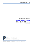
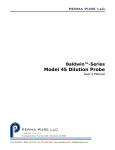
PERMA PURE LLC SDS™-Series 4C-D201/-D202 Supplemental Drying System User’s Manual PERMA PURE LLC 8 Executive Drive ▪ P.O. Box 2105 ▪ Toms River, NJ 08754 (732) 244-0010 ▪ (800) 337-3762 ▪ fax (732) 244-8140 ▪ www.permapure.com ▪ [email protected] SDS™-Series User’s Manual Doc. #219: Revision: 000 Page 2 of 12 PERMA PURE LLC Contents Unpacking ........................................................................................................................ 3 Introduction...................................................................................................................... 3 General description ............................................................................................................ 4 Specifications and features.................................................................................................. 4 Important safety warnings .................................................................................................. 5 Installation ....................................................................................................................... 6 Tools and hardware recommended for installation: .............................................................. 6 Location of SDS system................................................................................................... 6 Mounting....................................................................................................................... 7 Sample connections – Model SDS-4C-D201 (Refer to figure 4) .............................................. 8 Sample connections – Model SDS-4C-D202 ........................................................................ 8 Instrument air connections – all models............................................................................. 9 Your drying system is ready for use when ........................................................................ 10 Troubleshooting guide ...................................................................................................... 11 Replacement parts ........................................................................................................... 11 Appendix A: Warranty and disclaimers ................................................................................ 12 PERMA PURE LLC SDS™-Series User’s Manual Doc. #219: Revision: 000 Page 3 of 12 Unpacking Perma Pure has made every effort to ship you a high quality product that has been thoroughly inspected and tested. It has been carefully packed to ensure that it arrives at your facility in good condition. Even though every effort has been made to prevent damage during the transportation process, damage can occur by the carrier. This is out of control of Perma Pure and is the responsibility of the carrier to ensure that your equipment arrives intact and undamaged. Inspect outside packaging. If there is any visible damage, inform the carrier at the time of deliver. This inspection is important! Once the package is signed for, responsibility for any visible damage then transfers to the consignee. Unpack your equipment. Visually inspect the outside of your equipment for any damage. If there is any damage, contact the carrier immediately. Generally, a carrier must be notified within 24 hours of the delivery to make a hidden damage claim. Items in the carton include: (1) Model SDS Drying system (1) User’s Manual If any of the above parts are missing or damaged, call the helpline at (800) 337-3762 ext-145. Introduction Thank you for purchasing this product from Perma Pure LLC. This manual has been assembled so that it can answer all questions regarding operation. Please keep the operators manual near the equipment for future reference. There may also be optional equipment available that was not ordered at the time of original purchase, which may be described and/or illustrated in this manual. If you still have any questions regarding your equipment’s operation, available options or technical support, please contact your purchasing dealer or contact Perma Pure directly. Perma Pure LLC P.O. Box 2105 8 Executive Drive Toms River, NJ 08754 website: www.permapure.com Tel: 732-244-0010 Tel: 800-337-3762 (toll free US) Fax: 732-244-8140 e-mail: [email protected] This equipment is to be installed and operated by trained personnel, with sufficient command of the English language to clearly understand the instructions and safety warnings. 3 COPYRIGHT 2008, ALL RIGHTS RESERVED, Original Instructions SDS™-Series User’s Manual Doc. #219: Revision: 000 Page 4 of 12 PERMA PURE LLC General description Proven tube-in-shell membrane technology is the basis of the SDS™-Series Drying System, which selectively removes water vapor from a gas stream. The driving force is the vapor pressure differential between the sample gas and a purge gas counter-flowed outside the tubing. This difference drives the reaction, quickly drying the gas stream. The SDS-Series drying system is designed as an add-on to an existing conditioning system. It can also be used as the primary gas drying device, provided the sample is non-condensing at ambient temperature. Specifications and features • Sample flow rate: o 4C-D201 5 lpm maximum o 4C-D202 10 lpm maximum (single stream) 5 lpm maximum each (dual stream) • Sample inlet humidity: Non-condensing at room temperature • Sample outlet humidity: < -15°C dew point at maximum inlet flow and humidity conditions • Sample inlet pressure: 80 psig maximum • Sample inlet temperature: 90°C maximum • Dimensions: 24” x 6” x 6” • Enclosure: NEMA 12, IP 54, gray powder-coated finish • Purge air requirements: o Purge gas pressure: 30-150 psig o Purge gas humidity: less than -40°C dew point o Oil-free instrument air or nitrogen recommended • Connections: o Sample inlet: ¼” Kynar™ compression fitting o Sample outlet: ¼” Kynar compression fitting o Purge air inlet : ¼” female NPT o Purge air outlet: ¼” female NPT; allows for connection to outside vent PERMA PURE LLC SDS™-Series User’s Manual Doc. #219: Revision: 000 Page 5 of 12 Important safety warnings Please be sure to review the following basic safety procedures. These procedures represent the MINIMUM requirements to operate the equipment safely. It is the ultimate responsibility of the operator to ensure proper safety practices are utilized at the point of operation. • This equipment is NOT designed to operate in a wet environment. • Condensate is potentially dangerous. NEVER handle drain lines or any other item that • • • • • • • • • • • may have come in contact with the gas stream or any hazardous material, without adequate personal protective equipment. ALWAYS assume that any liquid present is hazardous. Sample gas is potentially dangerous. A leak test is recommended at initial startup and as often as necessary to maintain a safe working environment around the equipment. The gas stream exhaust must exit away from all personnel to prevent dangerous exposure. NEVER operate the equipment with any part of the enclosure unsecured. All operated doors and covers must be in place and secured prior to operation. Electrical current may be present behind covers or doors, even if tools are not necessary to access these components. NEVER attempt service on this equipment without first disconnecting all energy sources. Repair of this equipment should only be done by properly trained personnel that are familiar with the potential risks involved with servicing of the equipment. NEVER replace fuses with types other then the sample specification of type and current. Do not bypass this or any other safety device. NEVER operate this equipment if it is visibly damaged or the possibility exists that it may have been damaged. The use of components that have not been purchased through an authorized Perma Pure dealer or directly from Perma Pure may compromise the safety of the operator. Additionally, use of non-authorized components may change the operating characteristics of this equipment. Any changes to the equipment, that modify its operation in any way, are dangerous, and are strictly prohibited. Read the entire operating manual before attempting to set up or operate the equipment. Please heed all warning labels that are on the equipment. They are there to remind you of possible hazardous conditions. Verify the integrity of any mechanical and/or electrical connections that are made to the unit. Verify that the unit is connected to the proper rated power for the system. Verify that the unit is plumbed properly to operate effectively. 5 COPYRIGHT 2008, ALL RIGHTS RESERVED, Original Instructions SDS™-Series User’s Manual Doc. #219: Revision: 000 Page 6 of 12 PERMA PURE LLC Installation Tools and hardware recommended for installation: 5/8” wrench • (2) • (1) ¾” wrench • Teflon tape or pipe thread sealant • (4) ¼” dia. mounting screws, not included • Appropriate adaptor to connect to ¼” FNPT air line Location of SDS system P≤20 psig COOLER PUMP SDS Figure 1 – Pressurized Sample Configuration P≥-5 psig COOLER SDS PUMP Figure 2 – Sample Vacuum Configuration Pressure limitations are to prevent condensation in the SDS system; Vacuum limitations are to prevent the collapse of the membrane tubes PERMA PURE LLC SDS™-Series User’s Manual Doc. #219: Revision: 000 Page 7 of 12 Mounting 1. Attach system to secure wall using (4) ¼” dia. screws. 2. Refer to figure 3 for mounting dimensions. Figure 3 - Mounting Hole Dimension 7 COPYRIGHT 2008, ALL RIGHTS RESERVED, Original Instructions SDS™-Series User’s Manual Doc. #219: Revision: 000 Page 8 of 12 PERMA PURE LLC Sample connections – Model SDS-4C-D201 (Refer to figure 4) 1. Connect the sample supply line to the ¼” tube compression fitting labeled “Sample gas inlet”. 2. Connect the sample outlet line to the ¼” tube compression fitting labeled “Sample gas outlet”. Figure 4 - SDS-D201 Sample Connections Sample connections – Model SDS-4C-D202 The SDS-Series, Model 4C-D202 can be configured two ways, a high-flow, single stream system or a dual sample stream. Single stream application (Refer to figure 5) 1. Connect the sample supply line to the ¼” tube compression fitting labeled “Sample gas inlet”. 2. Connect the sample outlet line to the ¼” tube compression fitting labeled “Sample gas outlet”. PERMA PURE LLC SDS™-Series User’s Manual Doc. #219: Revision: 000 Page 9 of 12 Dual stream application (Refer to figure 5) 1. Remove the crossover tube. 2. Connect the sample stream 1 supply line to the ¼” tube compression fitting labeled “Sample gas inlet”. 3. Connect the sample stream 1 outlet line to the 1/4” tube compression fitting B. 4. Connect the sample stream 2 supply line to fitting A. 5. Connect the sample stream 2 outlet line to fitting labeled “Sample gas outlet”. A B Figure 5– SDS-D202 Sample Connections Instrument air connections – all models 1. Connect an instrument air line to the ¼” FNPT labeled “Instrument Air Inlet” in figure 6. NOTE: Instrument air must be oil-free and between 30-150 psig. 9 COPYRIGHT 2008, ALL RIGHTS RESERVED, Original Instructions SDS™-Series User’s Manual Doc. #219: Revision: 000 Page 10 of 12 PERMA PURE LLC 2. Optional exhaust connection: To vent the purge gas exhaust to a remote location, connect a line to the ¼” FNPT fitting labeled “Purge Air Vent”. This is suggested for gas samples that are toxic, flammable or otherwise hazardous. In case of failure of seal integrity, the sample will be vented to the remote location. For runs under 10 ft, ¼” OD tube is acceptable. For runs 10-40 ft, 3/8” OD tube is recommended. Figure 6 - Purge Gas Connections Your drying system is ready for use when Securely fastened to the wall Instrument air is connected and flowing Sample inlet and outlet tubing is connected SDS™-Series User’s Manual Doc. #219: Revision: 000 Page 11 of 12 PERMA PURE LLC Troubleshooting guide The SDS-Series is a very simple component of the sample conditioning system with no electricity, heat or moving parts to fail. Problems can arise if there is a failure upstream which causes liquid carryover or a high pressure or vacuum spike in the line. If these issues are suspected, please call the factory. We have a dedicated technical support and repair department to help in troubleshooting and replacement parts. Symptom Diagnostic Fix No purge flow Check pressure of the instrument air. Supply correct pressure, 30-150 psig. Restricted sample flow Bypass the SDS system and observe any changes. If the restriction disappears, the dryers in the SDS have failed and may need replacement; call factory at 732-244-0010 ext-145 for assistance. If no change is observed, check pump and other flow path components. No drying Check instrument air pressure and quality. Oil-free instrument air; 30-150 psig. Check for flow at exhaust point. 10-12 lpm for SDS-D201 20-24 lpm for SDS-D202 Check inlet for condensation in sample line. Call factory at 732-244-0010 ext145 for instructions on drying out system. Replacement parts 3DYK-001 Replacement membrane dryer 3RPA-001 Replacement instrument air regulator 11 COPYRIGHT 2008, ALL RIGHTS RESERVED, Original Instructions SDS™-Series User’s Manual Doc. #219: Revision: 000 Page 12 of 12 PERMA PURE LLC Appendix A: Warranty and disclaimers Perma Pure LLC Perma Pure (Seller) warrants that product supplied hereunder shall, at the time of delivery to Buyer, conform to the published specifications of Seller and be free from defects in material and workmanship under normal use and service. Seller’s sole obligation and liability under this warranty is limited to the repair or replacement at its factory, at Seller’s option, of any such product which proves defective within one year after the date of original shipment from seller’s factory (or for a normal usable lifetime if the product is a disposable or expendable item) and is found to be defective in material or workmanship by Seller’s inspection. Buyer agrees that (1) any technical advice, information, suggestions, or recommendations given to Buyer by Seller or any representative of Seller with respect to the product or the suitability or desirability of the product for an particular use or application are based solely on the general knowledge of Seller, are intended for information guidance only, and do not constitute any representation or warranty by Seller that the product shall in fact be suitable or desirable for any particular use or application; (2) Buyer takes sole responsibility for the use and applications to which the product is put and Buyer shall conduct all testing and analysis necessary to validate the use and application to which Buyer puts the product for which Buyer may recommend the use or application of the product by others; and (3) the characteristics, specifications, and/or properties of the product may be affected by the processing, treatment, handling, and/or manufacturing of the product by Buyer or others and Seller takes no responsibility for he nature or consequence of such operations or as to the suitability of the product for the purposes intended to be used by Buyer or others after being subjected to such operations. SELLER MAKES NO OTHER WARRANTY, EXPRESS OR IMPLIED, OF THE PRODUCT SUPPLIED HEREUNDER, INCLUDING, WITHOUT LIMITATION, IMPLIED WARRANTIES OF MERCHANTABILITY AND FITNESS FOR PARTICULAR PURPOSE, AND ALL SUCH WARRANTIES ARE HEREBY EXPRESSLY EXCLUDED. SELLER SHALL HAVE NO LIABILITY FOR LOSS OF PROFITS, OR SPECIAL, INCIDENTAL, OR CONSEQUENTIAL DAMAGES UNDER ANY CIRCUMSTANCES OR LEGAL THEORY, WHETHER BASED ON NEGLIGENCE, BREACH OF WARRANTY, STRICT LIABILITY, TORT, CONTRACT, OR OTHERWISE. SELLER SHALL IN NO EVENT BE LIABLE IN RESPECT OF THIS ORDER AND OR PRODUCT DELIVERED ON ACCOUNT OF THIS ORDER FOR ANY AMOUNT GREATER THAN THAT PAID TO SELLER ON ACCOUNT OF THIS ORDER.