1
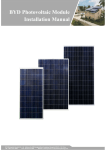
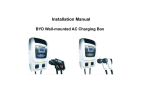
 BYD
[键
键入文档副标
标题]
Use
U r M
Man
nuaal
Ene
ergy Sttorage System
m
BYD COMPANY LIM
MITED 3009, BYD Roaad, Pingshan, Shenzhen, 51
18118, P.R.China NO.3
Web
bsite: www.bydenergy.com Provviding green, sstable and saffe electric pow
wer. Build Yourr Dreams Energy Storage System
Build Your Dream
—————————————————————————————————————————————— Content
1
Brief Instruction .......................................................................................................................... 3
2 Installation .................................................................................................................................... 3
2.1 Components List .................................................................................................. 3
2.2 Installation Place .................................................................................................. 3
2.3 Electric Connection .............................................................................................. 4
2.4 Startup.................................................................................................................. 8
2.4.1 System Operating Position ....................................................................................... 8
2.4.2 System Startup......................................................................................................... 9
3
Operation ................................................................................................................................. 10
3.1 Main interface ..................................................................................................... 10
3.2 Work modes ....................................................................................................... 11
3.2.1 Auto-local working mode ........................................................................................ 11
3.2.2 Manual-local working mode ................................................................................... 12
3.2.3 Remote working mode ........................................................................................... 13
3.2.4 DCAC configuration ............................................................................................... 14
4
System setting and maintenance ............................................................................................. 16
4.1 System setting .................................................................................................... 16
4.2 Maintenance ....................................................................................................... 17
4.2.1 Fault clear .............................................................................................................. 17
4.2.1 System alarm ......................................................................................................... 17
ESS Connection Topology ............................................................................................................. 19
ESS Specification .......................................................................................................................... 20 2 Energy Storage System
Build Your Dream
—————————————————————————————————————————————— 1
Brief Instruction
Energy storage system (ESS) P33B40 is designed
and developed by BYD Auto Industry
Company Limited, suitable for energy storage, power adjustment and frequency adjust occasions,
combined with other generator can composed micro-grid systems, and can coordinate the output
of each generator according to load requirements. In this way, the system provides the user with a
flexible energy storage system.
2
Installation
NOTE: During the installation and operation process, it is forbidden for
installer/customer to change the default setting and internal wiring of ESS, the
doing so will void the warranty. If there are any special requirements needed,
please contact your local dealer for support.
2.1 Components List
After unpacking the system, please refer to the following table to check whether the components
are complete, and free from damage.
Table 2.1 System Component
System Component
1
Control Cabinet ( PCS model, DCDC model, Distribution model)
1 PCS
2
Battery Cabinet (BMS control model, battery model)
1 PCS
2.2 Installation Place
ESS cabinet shall be placed on the plane ground and vertically installed. The proper
placement of system cabinet would ensure the reliability and safety of batteries. If the
site cannot meet the requirements, please stop the installation.
3 Energy Storage System
Build Your Dream
—————————————————————————————————————————————— Warning:
① Ensure the installation place is with good ventilation, and the ambient
environment meets the operation requirements of product;
② No flammable and explosive goods shall be placed within 4 meters of system;
③ Ambient temperature for the installation should be in the range of -10℃ to 50℃.
Warning:
① Smoking and fireworks are not allowed near the batteries;
② Ensure the environment of system cabinet is clean and ventilated;
③ Ensure the cable meets the standard; any incompetent cable may cause a fire.
2.3 Electric Connection
Figure 2.1 System component (the front of ESS)
Power Line Connection
4 Energy Storage System
Build Your Dream
—————————————————————————————————————————————— Figure 2.2 Power line connection between Control Cabinet & Battery Cabinet
(the front of ESS)
Communication Line Connection
Table 1.1 Communication line connection
Cable mark Corresponding terminal CAN#3 CAN(H/L)/ 85V‐264VAC 5 Energy Storage System
Build Your Dream
—————————————————————————————————————————————— Figure 2.3 Communication line connection between Control Cabinet & Battery Cabinet
(the back of ESS)
Terminal Block Connection
Table 1.2 Configuration Table of Terminals Connected
DESCRIPTION Cable Specification (Recommended)
PV panel connection terminal (20kW)
6mm2
LOAD U V W N
Load connection terminal (20kW)
6mm2
AC SOURSE U V W N
AC source connection terminal (20kW)
16mm2
TERMINAL BLOCK PV INPUT +
PV INPUT -
PE
6 Energy Storage System
Build Your Dream
—————————————————————————————————————————————— Figure. 2.4 Terminal connection (Wring model, the front of ESS)
7 Energy Storage System
Build Your Dream
—————————————————————————————————————————————— 2.4 Startup
2.4.1 System Operating Position
Figure. 2.5 ESS breakers and switches (the front of ESS)
8 Energy Storage System
Build Your Dream
—————————————————————————————————————————————— Figure. 2.6 breaker at the back of ESS
2.4.2 System Startup
1. Switch on MCB 6 and MCB 7of wiring model;
2. Close the breaker QF 2 of DCDC model;
3. Close the breaker QF 2 and switch on MCB 1 of DCDC model;
4. Switch on MCB 8 at the back of ESS;
5. Switch on MCB 3, MCB 4 and MCB 5;
6. 1)
If there is PV input, the system will power up and the running light will lighting;
2) If there is no PV input, press “SBT” button for 5 seconds, the system will power up and the
running light will lighting, and the HMI starts up normally;
9 Energy Storage System
Build Your Dream
—————————————————————————————————————————————— 3
Operation
3.1 Main interface
After power up, the HMI enter main interface:
Figure 3.1 Main Interface
Table 3.1 Main interface introduce
Screen mark
Introduction
A
System time, click it can enter time setting interface
B
System topology, click
to query the work state of each module, and
click breaker KM1, KM2 can control them when fulfill work condition
C
Click it can query ESS output curve
D
Control bar, have 4 sub menus: mode control, system control, system
alarm and system configuration
ESS set permissions for operation control, enter sub menu on control bar need password login,
and click any sub menu password keypad appear:
10 Energy Storage System
Build Your Dream
—————————————————————————————————————————————— Figure 3.2 Password keyboard
Click the numbers in the keyboard to input password,the default password is 123.
Clr: clear input number; Esc: exit, close the keyboard; Ent: enter, confirm the input number and
close the keyboard
NOTE:
Sub menu automatically logout when no operation for 5 min and enter screensaver mode, click
HMI to return main interface.
To prolong the HMI life, HMI backlight automatically turn off when no operation for 10 min, click
HMI to return screensaver mode.
3.2 Work modes
3.2.1 Auto-local working mode
Click “Mode ctrl.” and enter password. The default working mode of ESS is Auto-local.
Auto-local working mode: under this mode ESS will run automatically according to the battery
SOC and the DCAC configuration. DCAC configuration introduce in 4.2.4
Table 3.2 Default DCAC configuration and the ESS working
DCAC configuration item
Default value
Introduction
SOC of ESS supplying
power
95%
ESS automatically close KM1 and supply power to the
load when battery SOC is higher than 95%
SOC of diesel engine
supplying power
10%
ESS automatically open KM1 and close KM2 when
battery SOC is lower than 10%
SOC of DCAC starting
50%
When battery SOC is higher than 50%, click KM1can
manual close it, and ESS supply power to the load
11 Energy Storage System
Build Your Dream
—————————————————————————————————————————————— Figure 3.3 Default Mode control interface
Figure 3.4 KM1 manual close interface
3.2.2 Manual-local working mode
Manual-local working mode: under this mode ESS will run automatically according to the battery
SOC, the DCAC configuration and system control command.
In default mode control interface, click “Manual-local” button, the “manual -local” button
becomes orange and the current control mode switches to manual local control.
ESS working state is similar to auto-local working mode, the difference is you can control the
ESS standby and stop in “System ctrl”.
12 Energy Storage System
Build Your Dream
—————————————————————————————————————————————— Figure 3.5 Manual-local Mode control interface
Back to main interface and enter “System ctrl”.
Figure 3.6 System control interface
Click the “Stop” or “Standby” button in system control interface to stop or standby the ESS.
NOTE:
Only in Manual-local working mode the standby and stop operation in system control is
effective.
In Auto-local working mode system will continues working as long as external condition fulfilled,
you need to switch to Manual-local working mode if you want to stop the ESS.
3.2.3 Remote working mode
Remote working mode: under this mode, ESS will be control by remote terminal, HMI cannot
control the system.
13 Energy Storage System
Build Your Dream
—————————————————————————————————————————————— In default mode control interface, click “Manual-local” button, the button turn orange and the
current control mode switches to manual local control.
Figure 3.7 Remote Mode control interface
Figure 3.8 HMI cannot control ESS under remote mode
3.2.4 DCAC configuration
The DCAC configuration decides the ESS local working, and the default value can be
modified.
Click DCAC button to enter ACDC monitoring interface
14 Energy Storage System
Build Your Dream
—————————————————————————————————————————————— Figure 3.9 DCAC button
Figure 3.10 ACDC monitoring interface
Click “Para.config” to enter ACDC parameter configuration interface
15 Energy Storage System
Build Your Dream
—————————————————————————————————————————————— Figure 3.11 ACDC parameter configuration interface
The default DCAC configuration value can be change here.
NOTE:
The logic of the three SOC:
SOC of diesel engine supplying power < SOC of DCAC starting < SOC of ESS supplying power
4
System setting and maintenance
4.1 System setting
Click “system config.” on main interface to enter system setting interface. Figure 4.1 System configuration interface
Contains:
1. Setting the date & time, language, password
2. Query the operation record, version of software
3. Clear record of historical alarm
16 Energy Storage System
Build Your Dream
—————————————————————————————————————————————— Figure 4.2 Date&Time setting
4.2 Maintenance
4.2.1 Fault clear
If the component of ESS in fault condition, the component frame become red in main interface:
Figure 4.3 Componet frame become red when fault occur
Back to main interface and enter “System ctrl”, click “clear fault” button to clear the fault
NOTE:
If click the “clear fault” button when there is no fault, ESS will stop working.
4.2.1 System alarm
Click “System alarm” in main interface to query current system alarm.
17 Energy Storage System
Build Your Dream
—————————————————————————————————————————————— Figure 4.4 System current alarm
Click “History” button in system current alarm, can query the system history alarm
Figure 4.5 System history alarm
18 Energy Storage System
Build Your Dream
—————————————————————————————————————————————— ESS Connection Topology
19 Energy Storage System
Build Your Dream
—————————————————————————————————————————————— ESS Specification
Item
PCS
Parameter
P10B40-C20-220/60
Nominal Power
20KW
Output Voltage
220V/L-N
AC Phase
Three-phase Four-line +PE
Nominal Current
55A
Nominal Frequency
60HZ
Allowable Frequency Range
57~60.5HZ
Max. Efficiency
97.50%
Power Factor
-1~1
Current THD
<3%(Nominal Power)
(On-grid Operation)
Voltage THD
<5%(Nominal Power)
(Off-grid Operation)
On-grid Operation; Off-grid Operation;
Operation Mode
Micro-grid Operation
Over-load Capability
1.1 times 1min,1.2 times 10s
PV Charger
Nominal Power
20KW
Parameter
PV Voltage Range
250~350V
Battery
Nominal Voltage
409.6V
Parameter
Energy Storage Capacity
40KWh
Communication Interface
RS485
Cabinet Protection Grade
IP20 (Indoors)
Environment Temperature
-10~+50℃
System
Relative Humidity
5~95% (No Condensation)
Parameter
Max. Altitude
3000m
Cooling Method
Forced Air Cooling
Dimension (L*W*H)
1200*1200*2100 mm
Package Weight
1456 kg
20 B
Build Y
Your Drreamss User Manu
ual for ESS-- P20B40-C
C20
December,
r, 2013
Designed by
b BYD Ele
ectric Powe
er Research Institute
e, BYD Auto
o Industry Co., Ltd